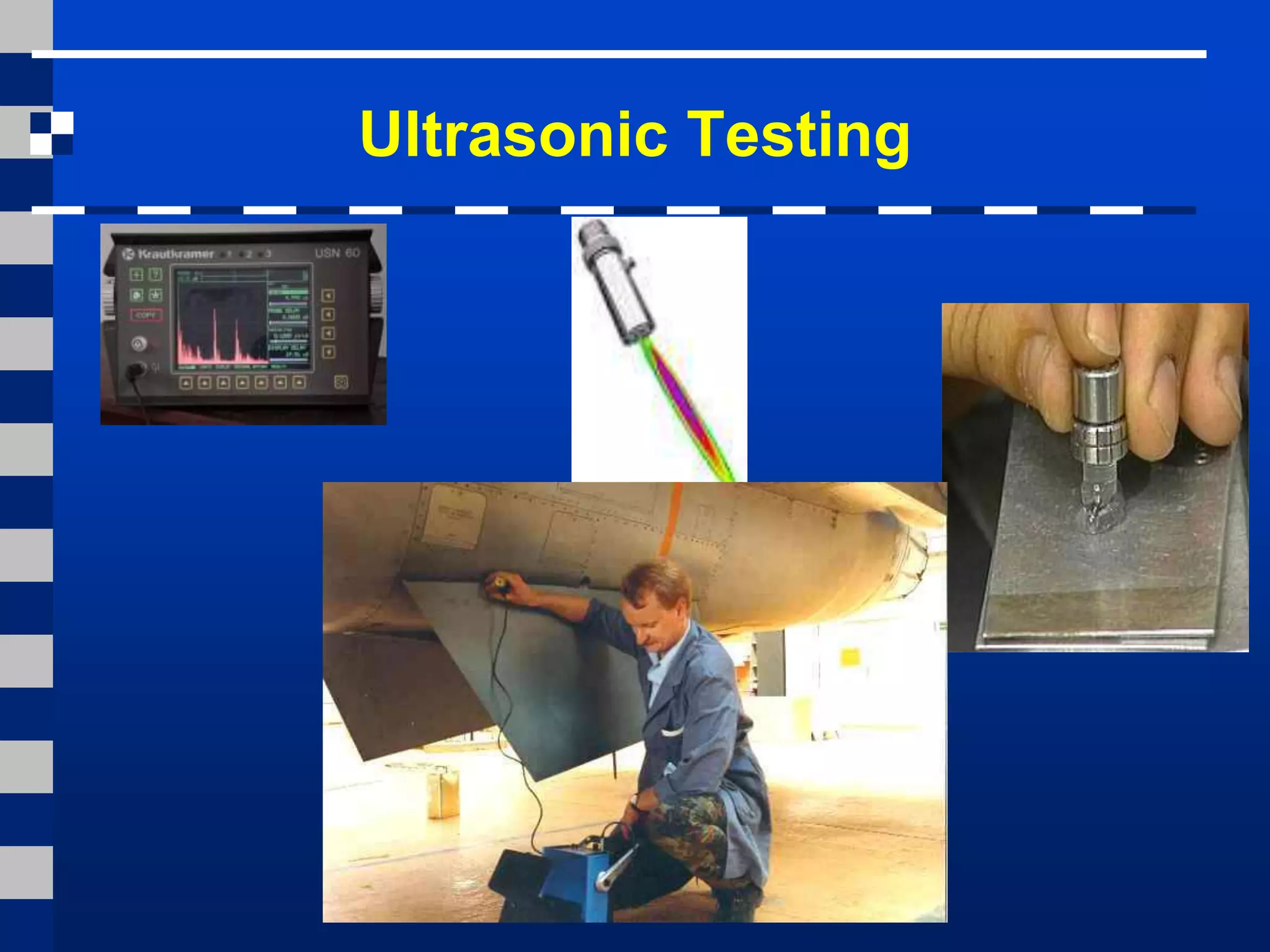
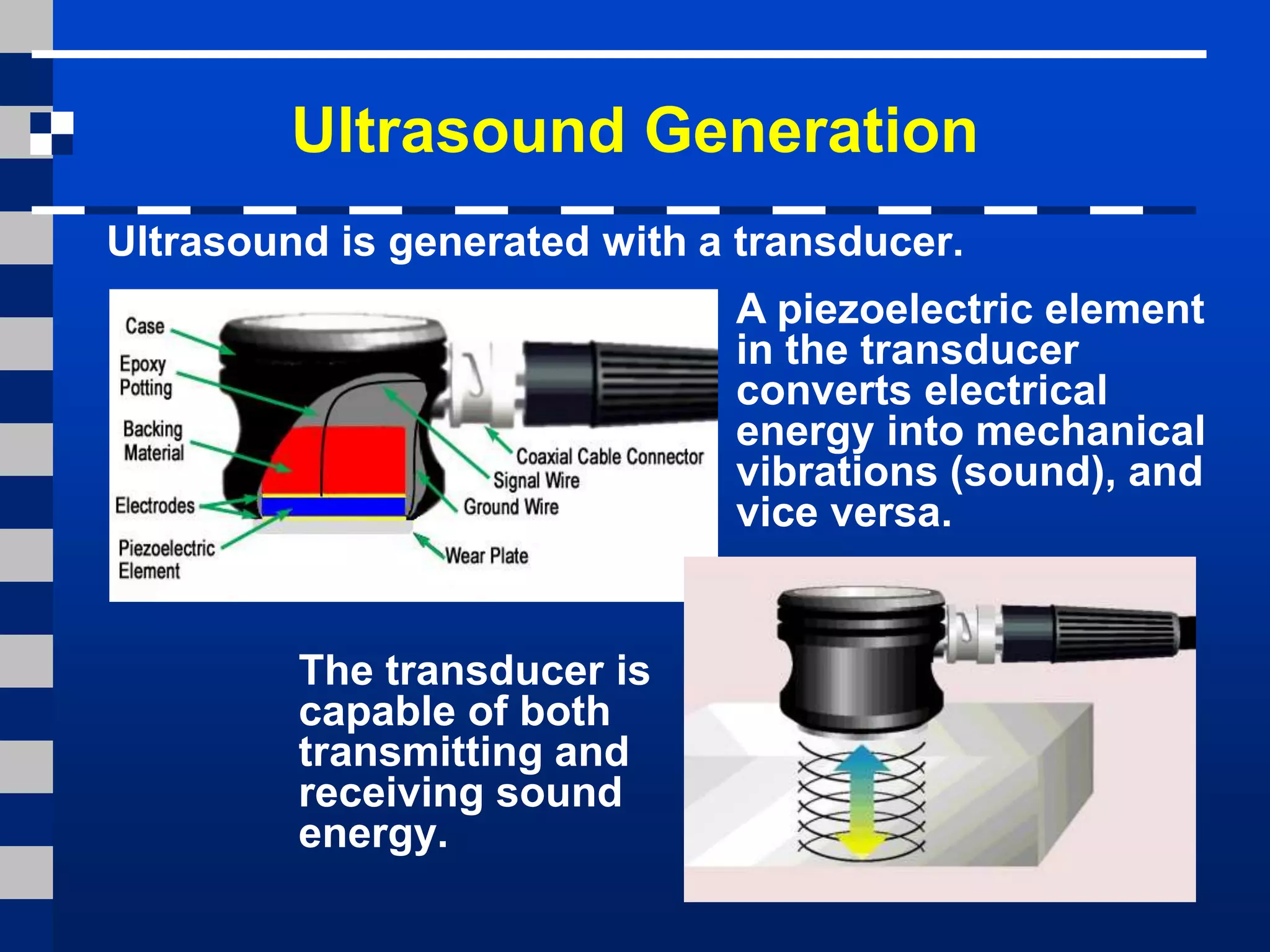
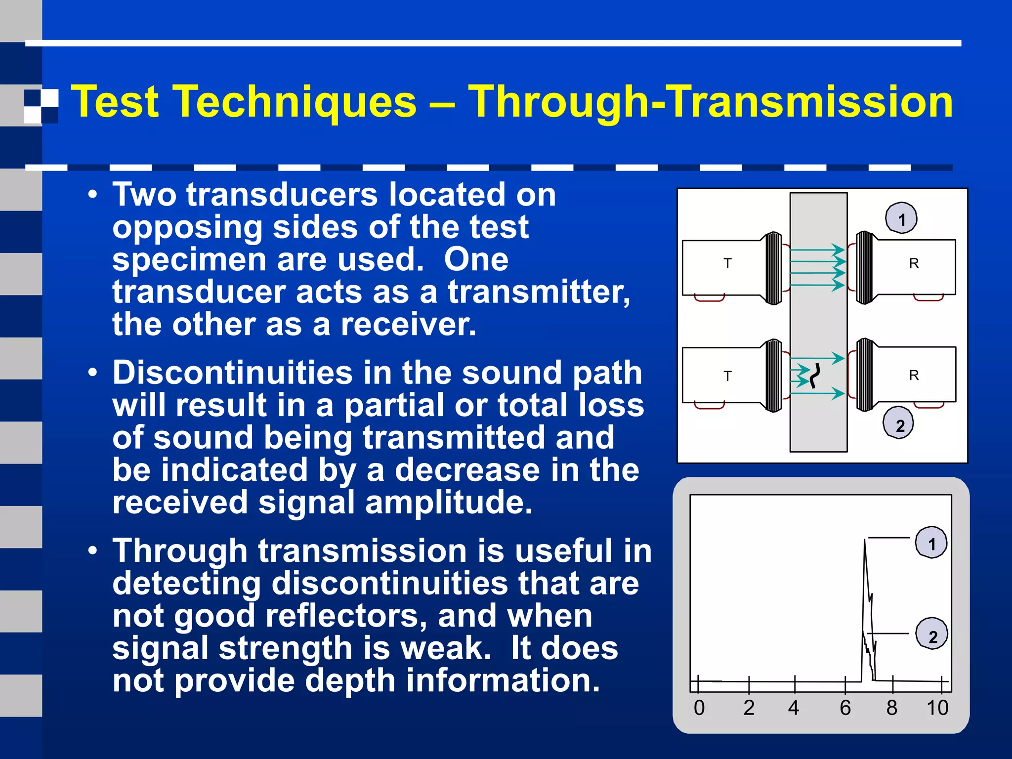
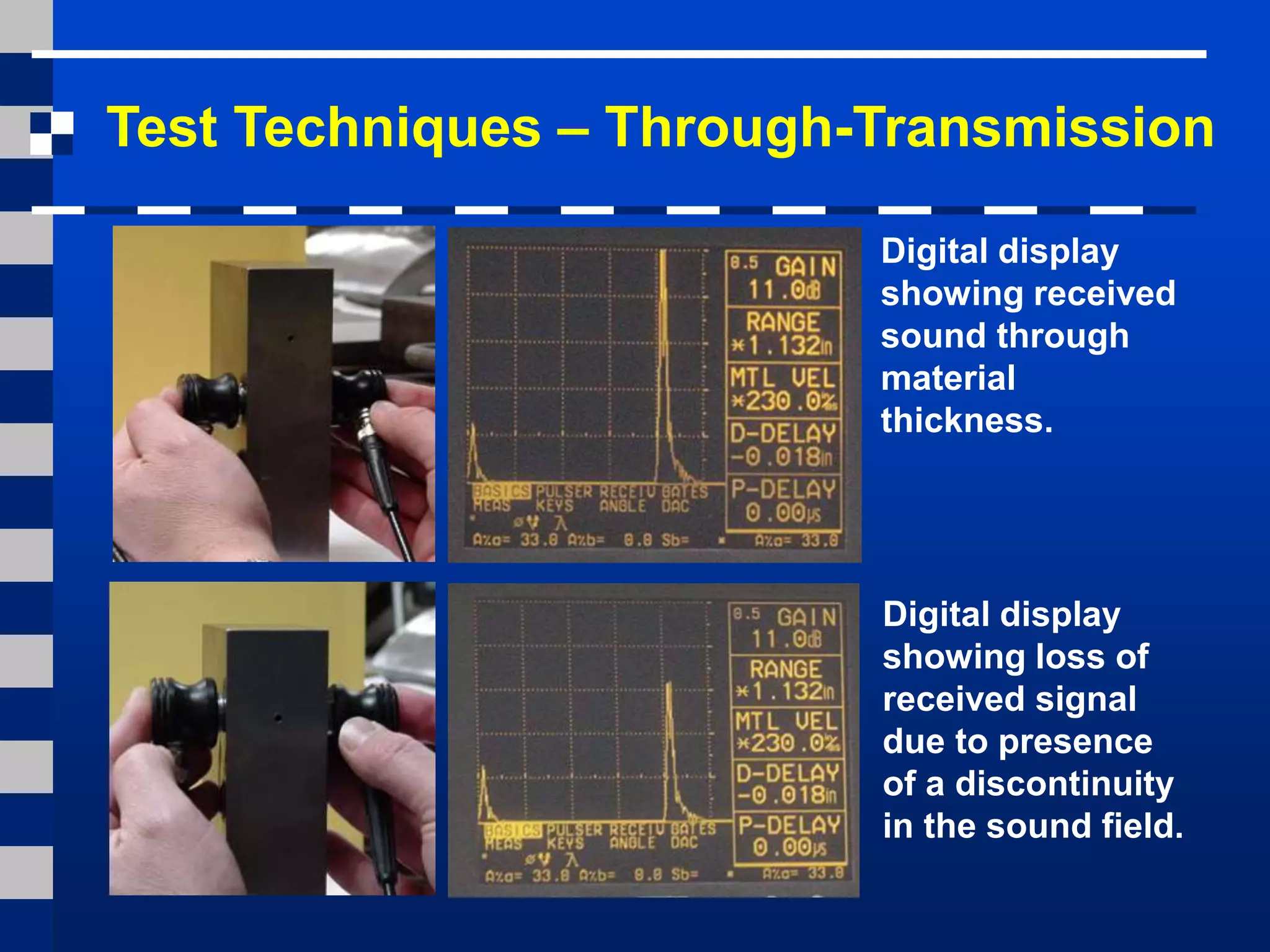
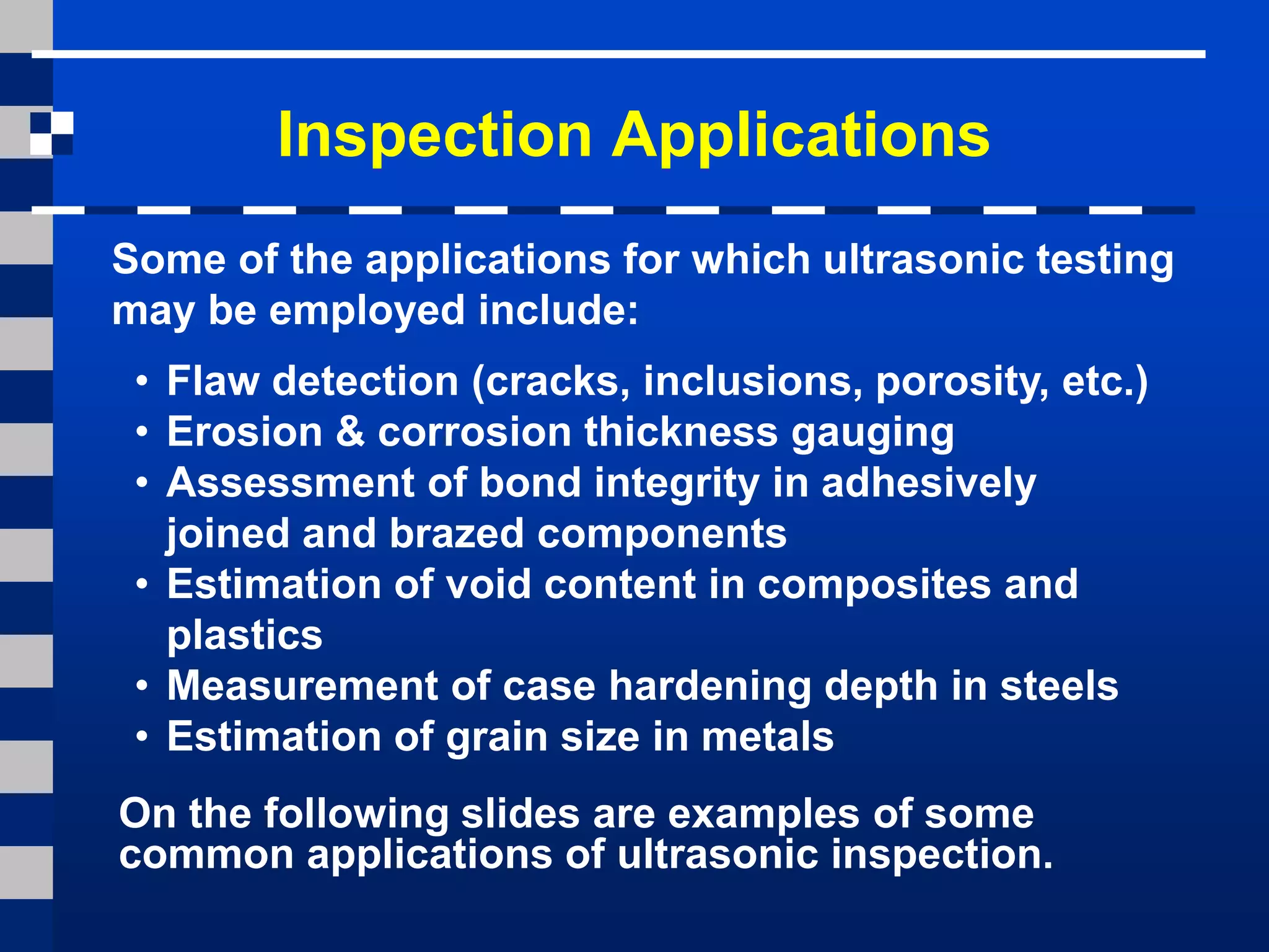
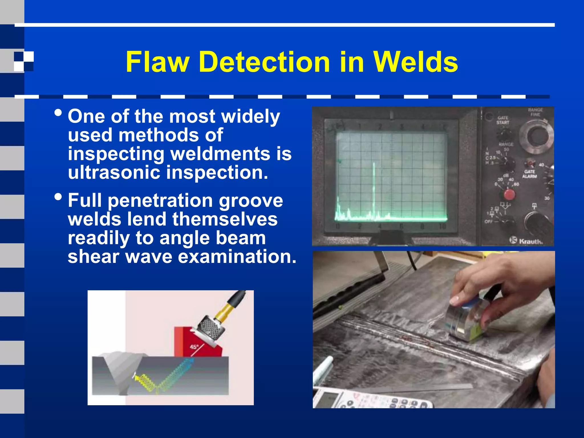
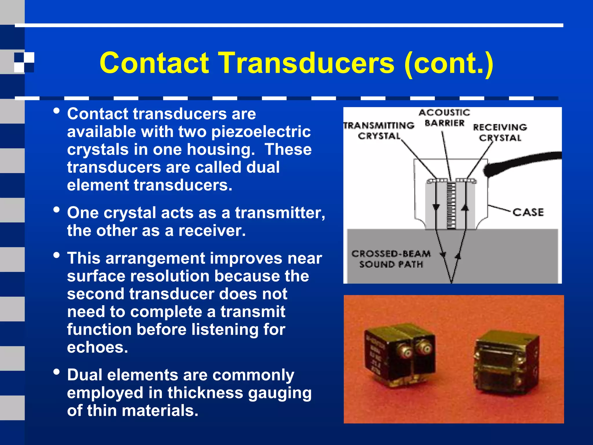
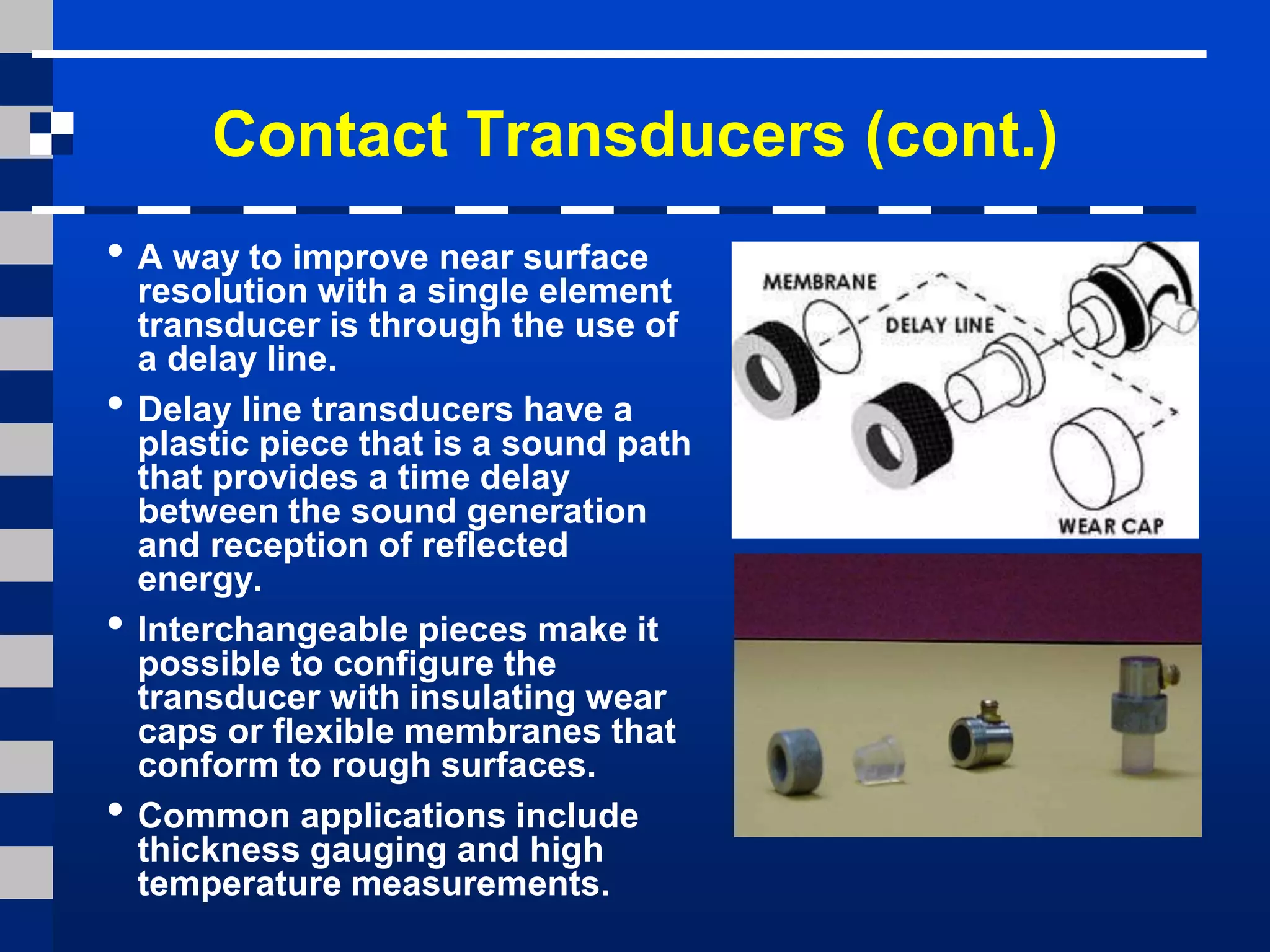
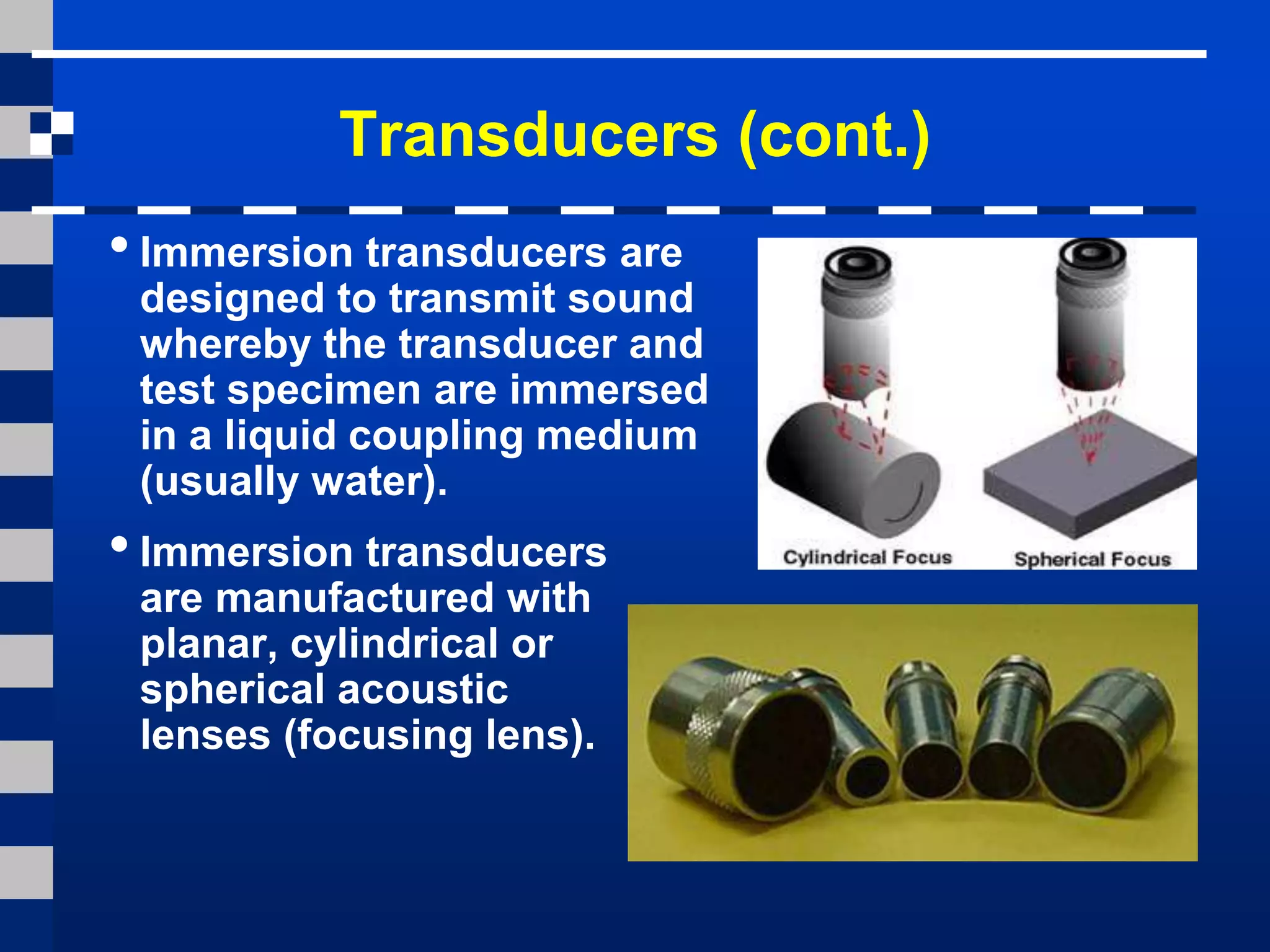
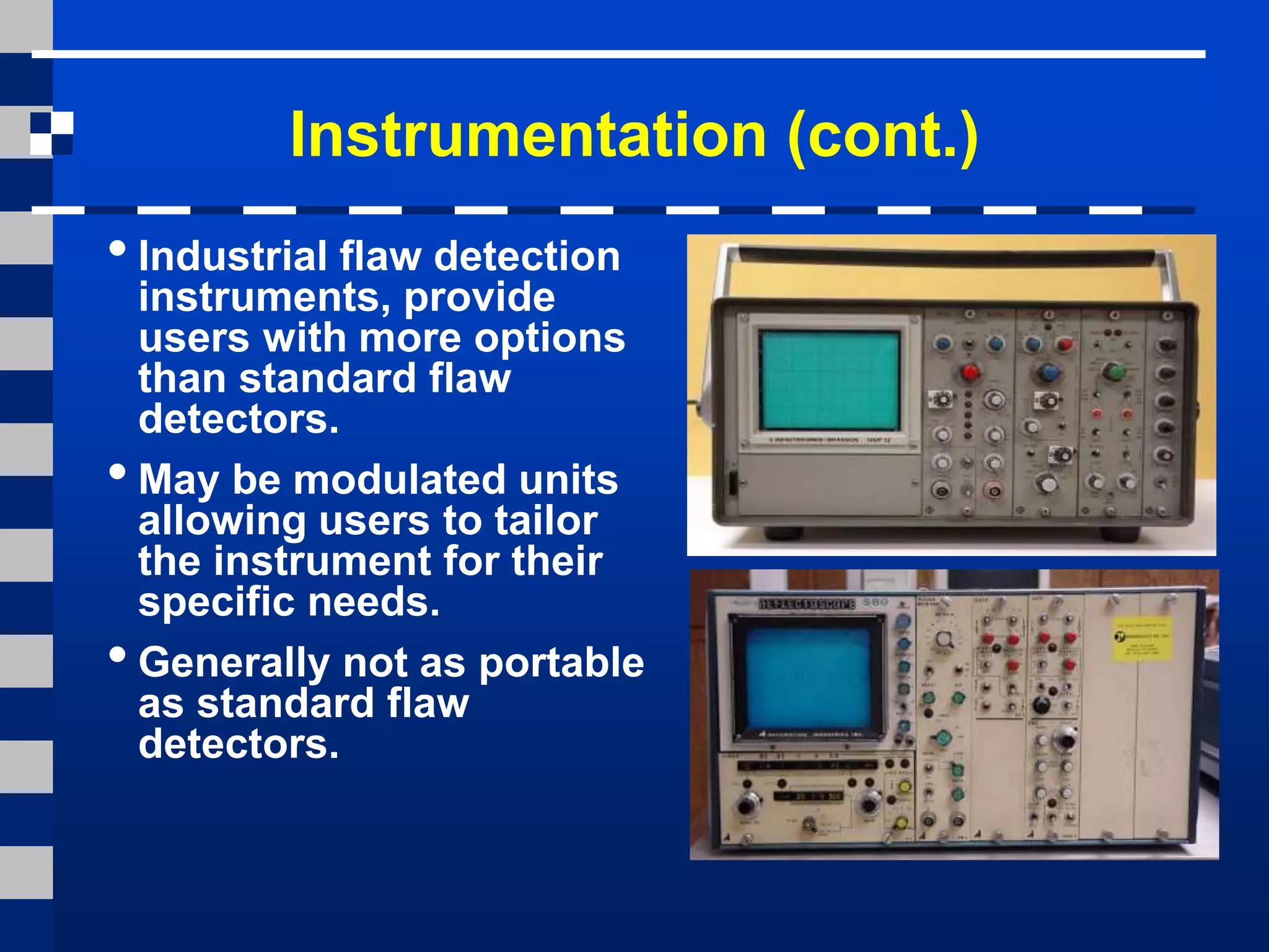
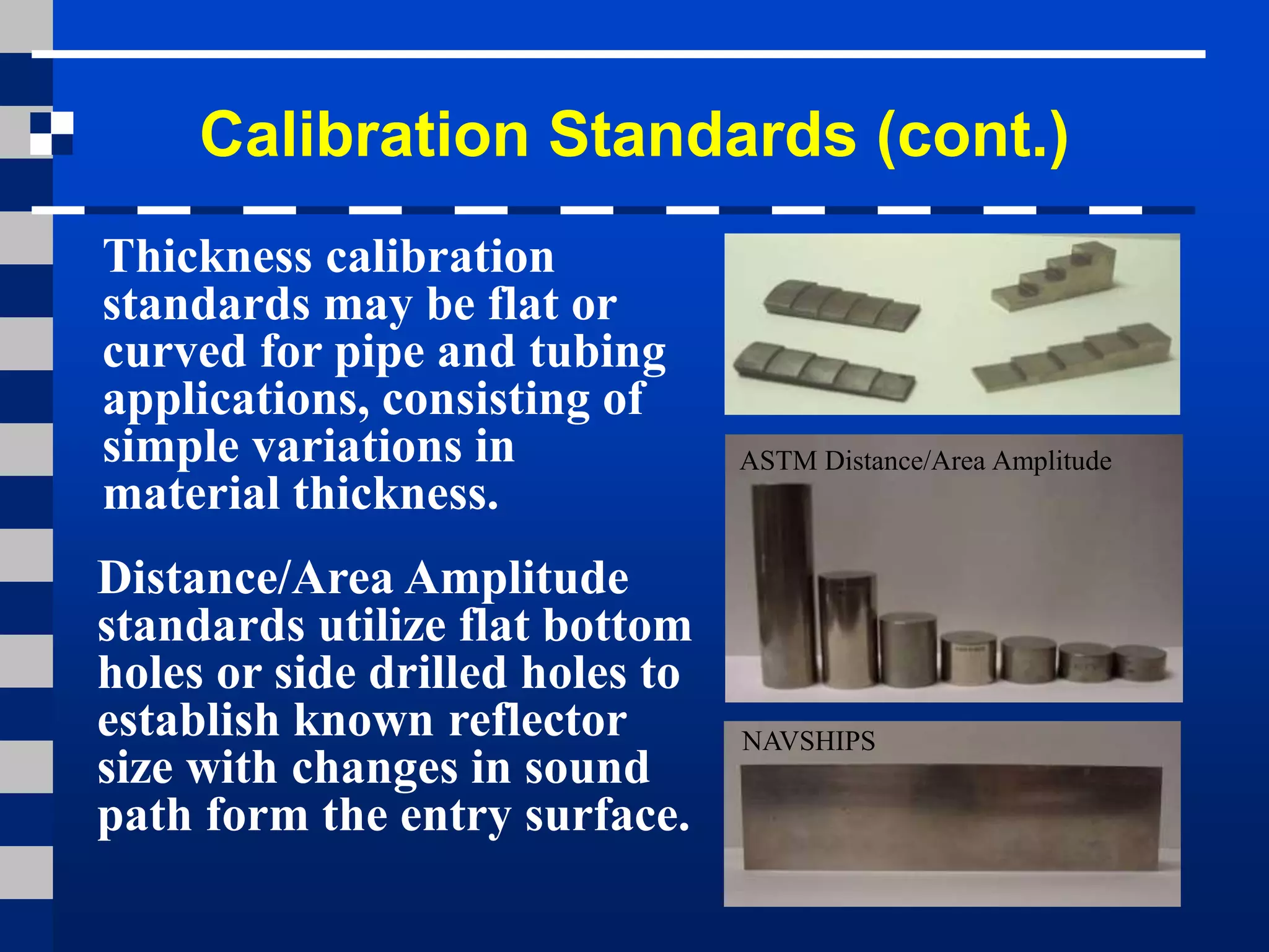
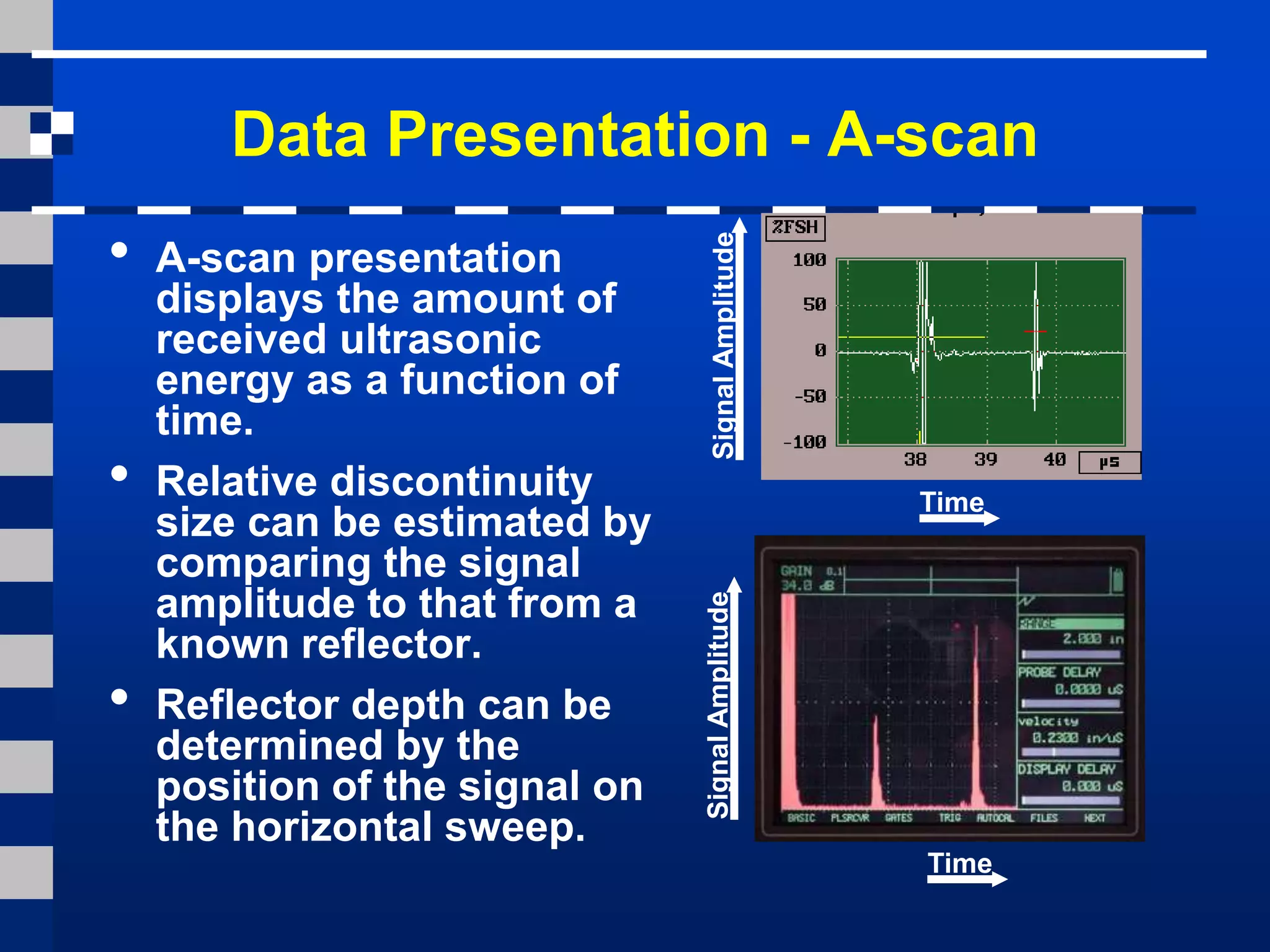
Ultrasonic testing uses high frequency sound waves to inspect materials for flaws and thickness measurements. It can be used on a variety of materials like castings, forgings and composites. There are different techniques like pulse-echo and through transmission. Equipment includes transducers to generate and receive sound, instrumentation to display signals, and calibration standards. Signals can be displayed as A-scans, B-scans or C-scans. Ultrasonic testing is sensitive to subsurface flaws but requires skilled technicians and may not work well on rough surfaces.
1.1 The aim of the experiment
The aim of the experiment is to test the usefulness of the ultrasonic waves, by passing them through different
solids one can find out a lot of physical properties like young’s modulus , defects, Poisson ratio, Velocity of
sound in respective material this is due to the response of the received ultrasonic waves.
1.2 Theory of experiment
Ultrasonic testing (UT) is a family of non-destructive testing (NDT) techniques based on the propagation of ultrasonic waves in the object or material tested. In most common UT applications, very short ultrasonic pulse-waves with center frequencies ranging from 0.1-15 MHz, and occasionally up to 50 MHz, are transmitted into materials to detect internal flaws or to characterize materials. A common example is ultrasonic thickness measurement, which tests the thickness of the test object, for example, to monitor pipework corrosion.
Ultrasonic testing is often performed on steel and other metals and alloys, though it can also be used on concrete, wood and composites, albeit with less resolution. It is used in many industries including steel and aluminium construction, metallurgy, manufacturing, aerospace, automotive and other transportation sectors.
M4 ndt me 367 introductiontoultrasonictestingHareesh K
This presentation explains the basics of ultrasonic inspection.Different practical aspects and various types of techniques are explained detail in this module.
NDT stands for Non-Destructive Testingg,aliHatem16
NDT stands for Non-Destructive Testing, which is a method used to evaluate the properties of a material, component, or system without causing damage or altering its integrity. This technique is commonly employed in various industries such as manufacturing, aerospace, automotive, construction, and energy production to ensure the quality and reliability of products and infrastructure.
Here's an overview of the main methods used in NDT:
Visual Inspection: This is the simplest form of NDT and involves visually examining a component or structure for surface defects, irregularities, or other visible anomalies.
Ultrasonic Testing (UT): UT uses high-frequency sound waves to detect internal flaws or defects in materials. A transducer sends ultrasonic waves into the material, and the reflections from internal boundaries or defects are analyzed to assess the integrity of the material.
Radiographic Testing (RT): RT involves passing X-rays or gamma rays through a material to create an image on a film or digital detector. This technique is useful for detecting internal defects such as cracks, voids, or inclusions.
Magnetic Particle Testing (MT): MT is used to detect surface and near-surface defects in ferromagnetic materials. A magnetic field is applied to the material, and iron particles are applied to the surface. These particles will gather at areas of magnetic flux leakage, indicating the presence of defects.
Liquid Penetrant Testing (PT): PT is used to detect surface-breaking defects in non-porous materials. A liquid dye penetrant is applied to the surface of the material, and after a certain dwell time, excess penetrant is removed. A developer is then applied, which draws the penetrant out of any surface defects, making them visible under UV light or visible light.
Eddy Current Testing (ET): ET is based on the principle of electromagnetic induction. A coil carrying an alternating current generates eddy currents in the material being tested. Changes in the eddy currents caused by defects or variations in material properties are detected and analyzed to identify flaws.
These methods can be used individually or in combination, depending on the specific requirements of the inspection. NDT plays a critical role in ensuring the safety, reliability, and performance of various components and structures, helping to prevent failures, accidents, and costly downtime.
Ultrasonic testing methods:
Introduction, Principle of operation, Piezoelectricity. Ultrasonic probes, CRO techniques,advantages,
Limitation & typical applications. Applications in inspection of castings, forgings,Extruded steel parts,
bars, pipes, rails and dimensions measurements. Case Study –Ultrasonography of human body.
Nondestructive testing (NDT) is the process of inspecting, testing, or evaluating materials, components or assemblies for discontinuities, or differences in characteristics without destroying the serviceability of the part or system. In other words, when the inspection or test is completed the part can still be used.
Explore the innovative world of trenchless pipe repair with our comprehensive guide, "The Benefits and Techniques of Trenchless Pipe Repair." This document delves into the modern methods of repairing underground pipes without the need for extensive excavation, highlighting the numerous advantages and the latest techniques used in the industry.
Learn about the cost savings, reduced environmental impact, and minimal disruption associated with trenchless technology. Discover detailed explanations of popular techniques such as pipe bursting, cured-in-place pipe (CIPP) lining, and directional drilling. Understand how these methods can be applied to various types of infrastructure, from residential plumbing to large-scale municipal systems.
Ideal for homeowners, contractors, engineers, and anyone interested in modern plumbing solutions, this guide provides valuable insights into why trenchless pipe repair is becoming the preferred choice for pipe rehabilitation. Stay informed about the latest advancements and best practices in the field.
Immunizing Image Classifiers Against Localized Adversary Attacksgerogepatton
This paper addresses the vulnerability of deep learning models, particularly convolutional neural networks
(CNN)s, to adversarial attacks and presents a proactive training technique designed to counter them. We
introduce a novel volumization algorithm, which transforms 2D images into 3D volumetric representations.
When combined with 3D convolution and deep curriculum learning optimization (CLO), itsignificantly improves
the immunity of models against localized universal attacks by up to 40%. We evaluate our proposed approach
using contemporary CNN architectures and the modified Canadian Institute for Advanced Research (CIFAR-10
and CIFAR-100) and ImageNet Large Scale Visual Recognition Challenge (ILSVRC12) datasets, showcasing
accuracy improvements over previous techniques. The results indicate that the combination of the volumetric
input and curriculum learning holds significant promise for mitigating adversarial attacks without necessitating
adversary training.
Final project report on grocery store management system..pdfKamal Acharya
In today’s fast-changing business environment, it’s extremely important to be able to respond to client needs in the most effective and timely manner. If your customers wish to see your business online and have instant access to your products or services.
Online Grocery Store is an e-commerce website, which retails various grocery products. This project allows viewing various products available enables registered users to purchase desired products instantly using Paytm, UPI payment processor (Instant Pay) and also can place order by using Cash on Delivery (Pay Later) option. This project provides an easy access to Administrators and Managers to view orders placed using Pay Later and Instant Pay options.
In order to develop an e-commerce website, a number of Technologies must be studied and understood. These include multi-tiered architecture, server and client-side scripting techniques, implementation technologies, programming language (such as PHP, HTML, CSS, JavaScript) and MySQL relational databases. This is a project with the objective to develop a basic website where a consumer is provided with a shopping cart website and also to know about the technologies used to develop such a website.
This document will discuss each of the underlying technologies to create and implement an e- commerce website.
CFD Simulation of By-pass Flow in a HRSG module by R&R Consult.pptxR&R Consult
CFD analysis is incredibly effective at solving mysteries and improving the performance of complex systems!
Here's a great example: At a large natural gas-fired power plant, where they use waste heat to generate steam and energy, they were puzzled that their boiler wasn't producing as much steam as expected.
R&R and Tetra Engineering Group Inc. were asked to solve the issue with reduced steam production.
An inspection had shown that a significant amount of hot flue gas was bypassing the boiler tubes, where the heat was supposed to be transferred.
R&R Consult conducted a CFD analysis, which revealed that 6.3% of the flue gas was bypassing the boiler tubes without transferring heat. The analysis also showed that the flue gas was instead being directed along the sides of the boiler and between the modules that were supposed to capture the heat. This was the cause of the reduced performance.
Based on our results, Tetra Engineering installed covering plates to reduce the bypass flow. This improved the boiler's performance and increased electricity production.
It is always satisfying when we can help solve complex challenges like this. Do your systems also need a check-up or optimization? Give us a call!
Work done in cooperation with James Malloy and David Moelling from Tetra Engineering.
More examples of our work https://www.r-r-consult.dk/en/cases-en/
Cosmetic shop management system project report.pdfKamal Acharya
Buying new cosmetic products is difficult. It can even be scary for those who have sensitive skin and are prone to skin trouble. The information needed to alleviate this problem is on the back of each product, but it's thought to interpret those ingredient lists unless you have a background in chemistry.
Instead of buying and hoping for the best, we can use data science to help us predict which products may be good fits for us. It includes various function programs to do the above mentioned tasks.
Data file handling has been effectively used in the program.
The automated cosmetic shop management system should deal with the automation of general workflow and administration process of the shop. The main processes of the system focus on customer's request where the system is able to search the most appropriate products and deliver it to the customers. It should help the employees to quickly identify the list of cosmetic product that have reached the minimum quantity and also keep a track of expired date for each cosmetic product. It should help the employees to find the rack number in which the product is placed.It is also Faster and more efficient way.
2. Introduction
• This module presents an introduction to the NDT
method of ultrasonic testing.
• Ultrasonic testing uses high frequency sound
energy to conduct examinations and make
measurements.
• Ultrasonic examinations can be conducted on a
wide variety of material forms including castings,
forgings, welds, and composites.
• A considerable amount of information about the
part being examined can be collected, such as the
presence of discontinuities, part or coating
thickness; and acoustical properties can often be
correlated to certain properties of the material.
3. Outline
• Applications
• Basic Principles of sound generation
• Pulse echo and through transmission testing
• Inspection applications
• Equipment
• Transducers
• Instrumentation
• Reference Standards
• Data presentation
• Advantages and Limitations
• Glossary of terms
4. Basic Principles of Sound
•Sound is produced by a vibrating body and travels
in the form of a wave.
•Sound waves travel through materials by vibrating
the particles that make up the material.
•The pitch of the sound
is determined by the
frequency of the wave
(vibrations or cycles
completed in a certain
period of time).
•Ultrasound is sound
with a pitch too high
to be detected by the
human ear.
5. Basic Principles of Sound (cont.)
• The measurement of sound waves from crest to
crest determines its wavelength (λ).
• The time is takes a sound wave to travel a
distance of one complete wavelength is the same
amount of time it takes the source to execute
one complete vibration.
• The sound wavelength
is inversely proportional
to its frequency. (λ = 1/f)
• Several wave modes of
vibration are used in
ultrasonic inspection.
The most common are
longitudinal, shear, and
Rayleigh (surface) waves.
6. Basic Principles of Sound (cont.)
• Ultrasonic waves are very similar to
light waves in that they can be reflected,
refracted, and focused.
• Reflection and refraction occurs when
sound waves interact with interfaces of
differing acoustic properties.
• In solid materials, the vibrational energy
can be split into different wave modes
when the wave encounters an interface
at an angle other than 90 degrees.
• Ultrasonic reflections from the presence
of discontinuities or geometric features
enables detection and location.
• The velocity of sound in a given material
is constant and can only be altered by a
change in the mode of energy.
7. Ultrasound Generation
The transducer is
capable of both
transmitting and
receiving sound
energy.
Ultrasound is generated with a transducer.
A piezoelectric element
in the transducer
converts electrical
energy into mechanical
vibrations (sound), and
vice versa.
8. Principles of Ultrasonic Inspection
•Ultrasonic waves are introduced into a material
where they travel in a straight line and at a
constant speed until they encounter a surface.
•At surface interfaces some of the wave energy is
reflected and some is transmitted.
•The amount of reflected or transmitted energy can
be detected and provides information about the
size of the reflector.
•The travel time of the sound can be measured and
this provides information on the distance that the
sound has traveled.
9. • Ultrasonic testing is a very versatile inspection
method, and inspections can be accomplished in a
number of different ways.
• Ultrasonic inspection techniques are commonly
divided into three primary classifications.
•Pulse-echo and Through Transmission
(Relates to whether reflected or transmitted energy is used)
•Normal Beam and Angle Beam
(Relates to the angle that the sound energy enters the test article)
•Contact and Immersion
(Relates to the method of coupling the transducer to the test
article)
Test Techniques
Each of these techniques will be discussed briefly
in the following slides.
10. • In pulse-echo testing, a transducer sends out a pulse of energy
and the same or a second transducer listens for reflected energy
(an echo).
• Reflections occur due to the presence of discontinuities and the
surfaces of the test article.
• The amount of reflected sound energy is displayed versus time,
which provides the inspector information about the size and the
location of features that reflect the sound.
f
Test Techniques - Pulse-Echo
plate
crack
0 2 4 6 8 10
initial
pulse
crack
echo
back surface
echo
UT Instrument Screen
11. Test Techniques – Pulse-Echo (cont.)
Digital display
showing signal
generated from
sound reflecting
off back surface.
Digital display
showing the presence
of a reflector midway
through material, with
lower amplitude back
surface reflector.
The pulse-echo technique allows testing when access to only one
side of the material is possible, and it allows the location of
reflectors to be precisely determined.
12. Test Techniques – Through-Transmission
0 2 4 6 8 10
2
11
• Two transducers located on
opposing sides of the test
specimen are used. One
transducer acts as a transmitter,
the other as a receiver.
• Discontinuities in the sound path
will result in a partial or total loss
of sound being transmitted and
be indicated by a decrease in the
received signal amplitude.
• Through transmission is useful in
detecting discontinuities that are
not good reflectors, and when
signal strength is weak. It does
not provide depth information.
T R
T R
11
2
13. Digital display
showing received
sound through
material
thickness.
Digital display
showing loss of
received signal
due to presence
of a discontinuity
in the sound field.
Test Techniques – Through-Transmission
14. Test Techniques – Normal and Angle Beam
• In normal beam testing, the sound
beam is introduced into the test
article at 90 degree to the surface.
• In angle beam testing, the sound
beam is introduced into the test
article at some angle other than
90.
• The choice between normal and
angle beam inspection usually
depends on two considerations:
- The orientation of the feature of
interest – the sound should be
directed to produce the largest
reflection from the feature.
- Obstructions on the surface of the
part that must be worked around.
15. 0 2 4 6 8 10
FWE
BWE
DE
2IP
IP = Initial Pulse
FWE = Front Wall
Echo
DE = Defect Echo
BWE = Back Wall
Echo
0 2 4 6 8 10
FWE
BWE
1IP1 2
Defect
Test Techniques – Contact Vs Immersion
• To get useful levels of sound energy into a material, the air
between the transducer and the test article must be removed.
This is referred to as coupling.
• In contact testing (shown on the previous slides) a couplant
such as water, oil or a gel is applied between the transducer
and the part.
• In immersion testing, the part and the transducer are place in a
water bath. This arrangement allows better movement of the
transducer while maintaining consistent coupling.
• With immersion testing, an echo from the front surface of the
part is seen in the signal but otherwise signal interpretation is
the same for the two techniques.
16. Inspection Applications
Some of the applications for which ultrasonic testing
may be employed include:
• Flaw detection (cracks, inclusions, porosity, etc.)
• Erosion & corrosion thickness gauging
• Assessment of bond integrity in adhesively
joined and brazed components
• Estimation of void content in composites and
plastics
• Measurement of case hardening depth in steels
• Estimation of grain size in metals
On the following slides are examples of some
common applications of ultrasonic inspection.
17. Thickness Gauging
• Ultrasonic thickness
gauging is routinely utilized
in the petrochemical and
utility industries to
determine various degrees
of corrosion/erosion.
• Applications
include piping
systems, storage
and containment
facilities, and
pressure vessels.
18. Flaw Detection - Delaminations
Signal showing multiple back
surface echoes in an unflawed area.
Additional echoes indicate
delaminations in the member.
Contact, pulse-echo inspection for delaminations
on 36” rolled beam.
19. Flaw Detection in Welds
•One of the most widely
used methods of
inspecting weldments is
ultrasonic inspection.
•Full penetration groove
welds lend themselves
readily to angle beam
shear wave examination.
20. Equipment
Equipment for ultrasonic testing is very
diversified. Proper selection is important to
insure accurate inspection data as desired
for specific applications.
In general, there are three basic components
that comprise an ultrasonic test system:
- Instrumentation
- Transducers
- Calibration Standards
21. Transducers
• Transducers are manufactured in a variety of
forms, shapes and sizes for varying applications.
• Transducers are categorized in a number of ways
which include:
- Contact or immersion
- Single or dual element
- Normal or angle beam
• In selecting a transducer
for a given application, it
is important to choose the
desired frequency,
bandwidth, size, and in some cases focusing
which optimizes the inspection capabilities.
22. Contact Transducers
Contact transducers are
designed to withstand
rigorous use, and usually
have a wear plate on the
bottom surface to protect
the piezoelectric element
from contact with the
surface of the test article.
Many incorporate
ergonomic designs for
ease of grip while
scanning along the
surface.
23. Contact Transducers (cont.)
• Contact transducers are
available with two piezoelectric
crystals in one housing. These
transducers are called dual
element transducers.
• One crystal acts as a transmitter,
the other as a receiver.
• This arrangement improves near
surface resolution because the
second transducer does not
need to complete a transmit
function before listening for
echoes.
• Dual elements are commonly
employed in thickness gauging
of thin materials.
24. Contact Transducers (cont.)
• A way to improve near surface
resolution with a single element
transducer is through the use of
a delay line.
• Delay line transducers have a
plastic piece that is a sound path
that provides a time delay
between the sound generation
and reception of reflected
energy.
• Interchangeable pieces make it
possible to configure the
transducer with insulating wear
caps or flexible membranes that
conform to rough surfaces.
• Common applications include
thickness gauging and high
temperature measurements.
25. Transducers (cont.)
• Angle beam transducers
incorporate wedges to
introduce a refracted shear
wave into a material.
• The incident wedge angle is
used with the material
velocity to determine the
desired refracted shear
wave according to Snell’s
Law)
• Transducers can use fixed
or variable wedge angles.
• Common application is in
weld examination.
26. Transducers (cont.)
• Immersion transducers are
designed to transmit sound
whereby the transducer and
test specimen are immersed
in a liquid coupling medium
(usually water).
• Immersion transducers
are manufactured with
planar, cylindrical or
spherical acoustic
lenses (focusing lens).
27. Instrumentation
• Ultrasonic equipment is usually purchased to
satisfy specific inspection needs, some users
may purchase general purpose equipment to
fulfill a number of inspection applications.
• Test equipment can be classified in a number of
different ways, this may include portable or
stationary, contact or immersion, manual or
automated.
• Further classification of instruments commonly
divides them into four general categories: D-
meters, Flaw detectors, Industrial and special
application.
28. Instrumentation (cont.)
•D-meters or digital
thickness gauge
instruments provide the
user with a digital
(numeric) readout.
•They are designed
primarily for
corrosion/erosion
inspection applications.
• Some instruments provide the user with both a
digital readout and a display of the signal. A
distinct advantage of these units is that they allow
the user to evaluate the signal to ensure that the
digital measurements are of the desired features.
29. Instrumentation (cont.)
•Flaw detectors are
instruments designed
primarily for the inspection
of components for defects.
•However, the signal can be
evaluated to obtain other
information such as
material thickness values.
•Both analog and digital
display.
•Offer the user options of
gating horizontal sweep
and amplitude threshold.
30. Instrumentation (cont.)
•Industrial flaw detection
instruments, provide
users with more options
than standard flaw
detectors.
•May be modulated units
allowing users to tailor
the instrument for their
specific needs.
•Generally not as portable
as standard flaw
detectors.
31. Instrumentation (cont.)
•Immersion ultrasonic scanning
systems are used for
automated data acquisition
and imaging.
•They integrate an immersion
tank, ultrasonic
instrumentation, a scanning
bridge, and computer controls.
•The signal strength and/or the
time-of-flight of the signal is
measured for every point in the
scan plan.
•The value of the data is plotted
using colors or shades of gray
to produce detailed images of
the surface or internal features
of a component.
32. Images of a Quarter Produced With an
Ultrasonic Immersion Scanning System
Gray scale image produced using
the sound reflected from the front
surface of the coin
Gray scale image produced using the
sound reflected from the back surface
of the coin (inspected from “heads” side)
33. Calibration Standards
Calibration is a operation of configuring the
ultrasonic test equipment to known values. This
provides the inspector with a means of comparing
test signals to known measurements.
Calibration standards come in a wide variety of
material types, and configurations due to the
diversity of inspection applications.
Calibration standards are typically manufactured
from materials of the same acoustic properties as
those of the test articles.
The following slides provide examples of specific
types of standards.
34. Calibration Standards (cont.)
Thickness calibration
standards may be flat or
curved for pipe and tubing
applications, consisting of
simple variations in
material thickness.
Distance/Area Amplitude
standards utilize flat bottom
holes or side drilled holes to
establish known reflector
size with changes in sound
path form the entry surface.
ASTM Distance/Area Amplitude
NAVSHIPS
35. Calibration Standards (cont.)
There are also calibration
standards for use in angle
beam inspections when
flaws are not parallel to
entry surface.
These standards utilized
side drilled holes, notches,
and geometric
configuration to establish
time distance and
amplitude relationships.
IIW
DSC DC Rhompas
SC
ASME Pipe Sec. XI
36. Qualification Standards
Qualification
standards differ from
calibration standards
in that their use is for
purposes of varying
proper equipment
operation and
qualification of
equipment use for
specific codes and
standards.
AWS Resolution
IOW Beam Profile
DC-dB Accuracy
37. Data Presentation
•Information from ultrasonic testing can be
presented in a number of differing formats.
•Three of the more common formats include:
• A-scan
• B-scan
• C-scan
These three formats will be discussed in the next
few slides.
38. Data Presentation - A-scan
• A-scan presentation
displays the amount of
received ultrasonic
energy as a function of
time.
• Relative discontinuity
size can be estimated by
comparing the signal
amplitude to that from a
known reflector.
• Reflector depth can be
determined by the
position of the signal on
the horizontal sweep.
Time
SignalAmplitudeSignalAmplitude
Time
39. Data Presentation - B-scan
•B-scan presentations
display a profile view
(cross-sectional) of a test
specimen.
•Only the reflector depth in
the cross-section and the
linear dimensions can be
determined.
•A limitation to this display
technique is that
reflectors may be masked
by larger reflectors near
the surface.
40. Data Presentation - C-scan
• The C-scan presentation displays a plan type view
of the test specimen and discontinuities.
• C-scan presentations are produced with an
automated data acquisition system, such as in
immersion scanning.
• Use of A-scan in conjunction with C-scan is
necessary when depth determination is desired.
Photo of a Composite
Component
C-Scan Image of
Internal Features
41. Advantage of Ultrasonic Testing
• Sensitive to both surface and subsurface
discontinuities.
• Depth of penetration for flaw detection or measurement
is superior to other methods.
• Only single-sided access is needed when pulse-echo
technique is used.
• High accuracy in determining reflector position and
estimating size and shape.
• Minimal part preparation required.
• Electronic equipment provides instantaneous results.
• Detailed images can be produced with automated
systems.
• Has other uses such as thickness measurements, in
addition to flaw detection.
42. Limitations of Ultrasonic Testing
• Surface must be accessible to transmit ultrasound.
• Skill and training is more extensive than with some other
methods.
• Normally requires a coupling medium to promote transfer
of sound energy into test specimen.
• Materials that are rough, irregular in shape, very small,
exceptionally thin or not homogeneous are difficult to
inspect.
• Cast iron and other coarse grained materials are difficult
to inspect due to low sound transmission and high signal
noise.
• Linear defects oriented parallel to the sound beam may
go undetected.
• Reference standards are required for both equipment
calibration, and characterization of flaws.
43. Glossary of Terms
•Acoustical properties: ultrasonic material characteristics
such as velocity, impedance, and attenuation.
•ASTM: acronym for American Society for Testing and
Materials. This society is extensively involved in
establishing standards for materials and the testing of
materials.
•Back reflection: a display signal that corresponds to the
far surface of a test specimen, side opposite to transducer
when testing with longitudinal waves.
•Band width: a range of frequencies either transmitted or
received, may be narrow or broad range.
•B-scan: presentation technique displaying data in a cross-
sectional view.
44. Glossary of Terms
•Calibration: a sequence of instrument control
adjustments/instrument responses using known values to
verify instrument operating characteristics. Allows
determination of unknown quantities from test materials.
•CRT: acronym for Cathode Ray Tube. Vacuum tube that
utilizes one or more electron guns for generating an image.
•C-scan: presentation technique that displays specimen
data in a plan type view.
•DAC (Distance Amplitude Correction-curves): a
graphical method of allowing for material attenuation.
Percentage of DAC is often used as a means of acceptance
criteria.
•Discontinuity: an interruption in the physical structure of a
material, examples include fissures, cracks, and porosity.
45. Glossary of Terms
• IIW: calibration standard meeting the specification of the
International Institute of Welding.
• Longitudinal (Compression) waves: ultrasonic mode of
propagation in which the particle vibration is parallel to the
direction of propagation.
• Near Surface Resolution: the ability of an ultrasonic system
to display reflectors located close to the entry surface.
• Pulse-echo: ultrasonic test method that utilizes reflected
sound as a means of collecting test data.
• Rayleigh (Surface) waves: ultrasonic mode of propagation
where the sound travels along the surface, particle vibration is
elliptical.
46. Glossary of Terms
• Reflection: the changing in direction of sound waves as they
strike a surface.
• Snell’s Law: an equation of ratios used to determine incident
or refracted angle of sound, denotes angle/velocity
relationship.
• Sweep display: horizontal line on the lower portion of the
display, often called the time base line.
• Through transmission: test technique in which ultrasound is
transmitted from one transducer and received by a separate
transducer on the opposite side of the test specimen.
• Wavelength: the distance that a sound wave travels as it
completes one cycle, normally measured in inches or
millimeters.