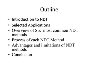
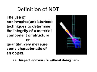
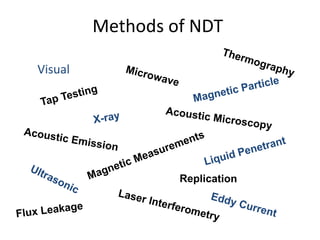
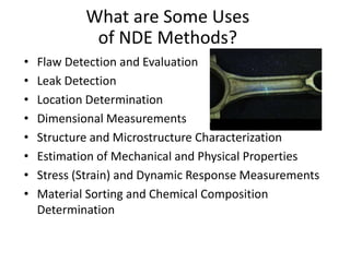
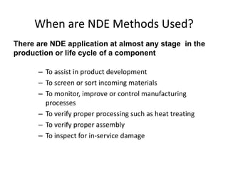
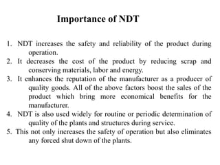
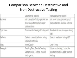
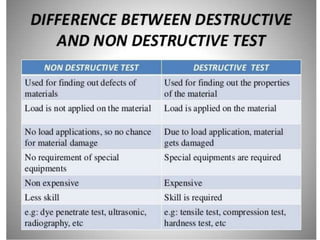
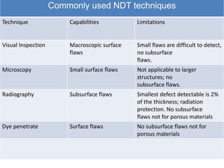
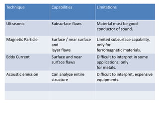
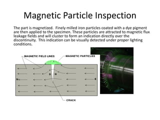
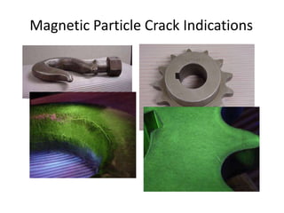
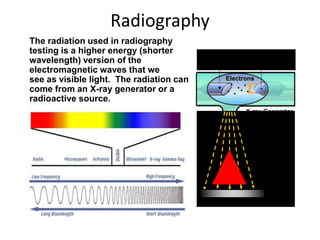
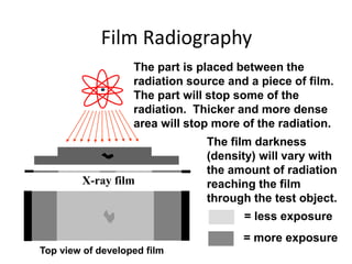
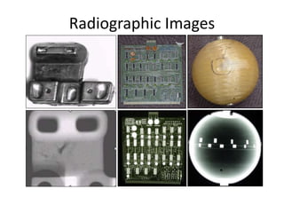
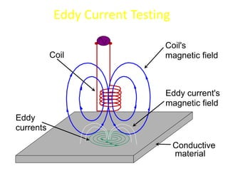
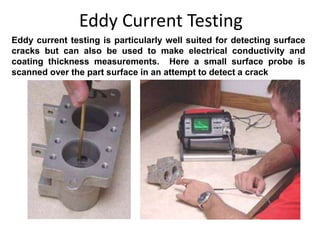
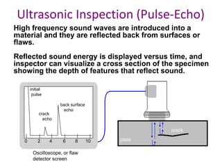
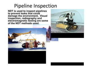
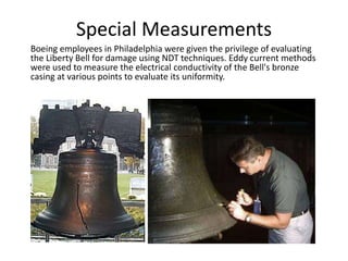
UNIT 1
Introduction to Non-destructive Testing
BY
SHIVAM SHARMA
Outline
• Introduction to NDT
• Selected Applications
• Overview of Six most common NDT
methods
• Process of each NDT Method
• Advantages and limitations of NDT
methods
• Conclusion
The use of
noninvasive(undisturbed)
techniques to determine
the integrity of a material,
component or structure
or
quantitatively measure
some characteristic of
an object.
i.e. Inspect or measure without doing harm.
Definition of NDT
Methods of NDT
Visual
What are Some Uses
of NDE Methods?
• Flaw Detection and Evaluation
• Leak Detection
• Location Determination
• Dimensional Measurements
• Structure and Microstructure Characterization
• Estimation of Mechanical and Physical Properties
• Stress (Strain) and Dynamic Response Measurements
• Material Sorting and Chemical Composition
Determination
Fluorescent penetrant indication
When are NDE Methods Used?
– To assist in product development
– To screen or sort incoming materials
– To monitor, improve or control manufacturing
processes
– To verify proper processing such as heat treating
– To verify proper assembly
– To inspect for in-service damage
There are NDE application at almost any stage in the
production or life cycle of a component
1. NDT increases the safety and reliability of the product during
operation.
2. It decreases the cost of the product by reducing scrap and
conserving materials, labor and energy.
3. It enhances the reputation of the manufacturer as a producer of
quality goods. All of the above factors boost the sales of the
product which bring more economical benefits for the
manufacturer.
4. NDT is also used widely for routine or periodic determination of
quality of the plants and structures during service.
5. This not only increases the safety of operation but also eliminates
any forced shut down of the plants.
Importance of NDT
Scope of NDT
• Non-destructive testing is a descriptive term used for the
examination of materials and components in such a way that
allows materials to be examined without changing or
destroying their usefulness. NDT or NDE can be used to
find, size and locate surface and subsurface flaws and
defects.
• NDT plays a crucial role in everyday life and is necessary to
assure safety and reliability. Typical examples are found in
aircraft, spacecraft (shuttle), motor vehicles, pipelines,
bridges, trains, power stations, refineries, buildings and oil
platforms which are all inspected using NDT.
Scope of NDT Cont..
• NDT is a Quality Assurance management tool which can
give impressive results when used correctly. It requires an
understanding of the various methods available, their
capabilities and limitations, knowledge of the relevant
standards and specifications for performing the tests
NDT is used typically for the following reasons:
Accident prevention and to reduce costs
To improve product reliability
To determine acceptance to a given requirement
To give information on repair criteria.
NDT methods are very useful in several fields:
In automotive-engine parts, frame and other accessories.
Aviation field space and air frame.
In power plant- propeller, engines, gas turbines, heat
exchangers etc.
In surface flaws, cracks, gagging, dimensions etc..
In construction of bridges, structures.
Manufacturing of machine parts, casting, forging
Submarines, naval ships
Medical applications( X-rays and gamma rays)
In railways.
Scope of NDT
Comparison Between Destructive and
Non Destructive Testing
Commonly used NDT techniques
Technique Capabilities Limitations
Visual Inspection Macroscopic surface
flaws
Small flaws are difficult to detect,
no subsurface
flaws.
Microscopy Small surface flaws Not applicable to larger
structures; no
subsurface flaws.
Radiography Subsurface flaws Smallest defect detectable is 2%
of the thickness; radiation
protection. No subsurface
flaws not for porous materials
Dye penetrate Surface flaws No subsurface flaws not for
porous materials
Technique Capabilities Limitations
Ultrasonic Subsurface flaws Material must be good
conductor of sound.
Magnetic Particle Surface / near surface
and
layer flaws
Limited subsurface capability,
only for
ferromagnetic materials.
Eddy Current Surface and near
surface flaws
Difficult to interpret in some
applications; only
for metals.
Acoustic emission Can analyze entire
structure
Difficult to interpret, expensive
equipments.
Six Most Common NDT Methods
1. Visual Testing (VT)
2. Dye Penetrant Testing (DPT)
3. Magnetic Particle Testing (MPT)
4. Ultrasonic Testing (UT)
5. Eddy Current Testing (ECT)
6. Radiography Testing (RT)
Visual Testing
Visual testing is the most basic and common inspection
method involves in using of human eyes to look for
defects. But now it is done by the use special tools such
as video scopes, magnifying glasses, mirrors, or
borescopes to gain access and more closely inspect the
subject area.
Visual Testing Equipments:
•Mirrors (especially small, angled mirrors),
•Magnifying glasses,
•Microscopes (optical and electron),
•Borescopes and fiber optic borescopes,
•Closed circuit television (CCTV) systems,
•Videoscope.
Most basic and common
inspection method.
Tools include
fiberscopes,
borescopes, magnifying
glasses and mirrors.
Robotic crawlers permit
observation in hazardous or
tight areas, such as air
ducts, reactors, pipelines.
Portable video inspection
unit with zoom allows
inspection of large tanks
and vessels, railroad tank
cars, sewer lines.
Visual Inspection
• A liquid with high surface wetting characteristics
is applied to the surface of the part and allowed
time to seep into surface breaking defects.
• The excess liquid is removed from the surface
of the part.
• A developer (powder) is applied to pull the
trapped penetrant out the defect and spread it
on the surface where it can be seen.
• Visual inspection is the final step in the
process. The penetrant used is often loaded
with a fluorescent dye and the inspection is
done under UV light to increase test
sensitivity.
Liquid Penetrant Inspection
Magnetic Particle Inspection
The part is magnetized. Finely milled iron particles coated with a dye pigment
are then applied to the specimen. These particles are attracted to magnetic flux
leakage fields and will cluster to form an indication directly over the
discontinuity. This indication can be visually detected under proper lighting
conditions.
Magnetic Particle Crack Indications
Radiography
The radiation used in radiography
testing is a higher energy (shorter
wavelength) version of the
electromagnetic waves that we
see as visible light. The radiation can
come from an X-ray generator or a
radioactive source.
High Electrical Potential
Electrons
-
+
X-ray Generator
or Radioactive
Source Creates
Radiation
Exposure Recording Device
Radiation
Penetrate
the Sample
Film Radiography
Top view of developed film
X-ray film
The part is placed between the
radiation source and a piece of film.
The part will stop some of the
radiation. Thicker and more dense
area will stop more of the radiation.
= more exposure
= less exposure
The film darkness
(density) will vary with
the amount of radiation
reaching the film
through the test object.
Radiographic Images
Conductive
material
Coil
Coil's
magnetic field
Eddy
currents
Eddy current's
magnetic field
Eddy Current Testing
Eddy current testing is particularly well suited for detecting surface
cracks but can also be used to make electrical conductivity and
coating thickness measurements. Here a small surface probe is
scanned over the part surface in an attempt to detect a crack
High frequency sound waves are introduced into a
material and they are reflected back from surfaces or
flaws.
Reflected sound energy is displayed versus time, and
inspector can visualize a cross section of the specimen
showing the depth of features that reflect sound.
f
plate
crack
0 2 4 6 8 10
initial
pulse
crack
echo
back surface
echo
Oscilloscope, or flaw
detector screen
Ultrasonic Inspection (Pulse-Echo)
Ultrasonic Imaging
Gray scale image produced using
the sound reflected from the front
surface of the coin
Gray scale image produced using the
sound reflected from the back surface
of the coin (inspected from “heads” side)
High resolution images can be produced by plotting
signal strength or time-of-flight using a computer-
controlled scanning system.
Advantages of NDT
1. Analysis of parts can be done without
breaking it.
2. Cost saving procedure.
3. Improves the quality of production.
4. Save times in production evaluation.
5. Evaluation can be done at manufacturing
stage or in service stage.
6. Portable mode of inspection.
7. Surface defects and inside defects can be
easily evaluated.
Applications
1. Flaw detection & evaluation
2. Leak detection
3. Location Determination
4. Dimensional measurement
5. Structure and Microstructure characterization
6. Estimation of Mechanical and Physical Properties
7. Stress (strain) and Dynamic response.
Common Application of NDT
• Inspection of Raw Products
• Inspection Following Secondary
Processing
• In-Services Damage Inspection
Inspection of Raw Products
• Forgings,
• Castings,
• Extrusions,
• etc.
Inspection Following Secondary Processing
• Machining
• Welding
• Grinding
• Heat treating
• Plating
• etc.
Inspection For
In-Service Damage
• Cracking
• Corrosion
• Erosion/Wear
• Heat Damage
• etc.
Power Plant Inspection
Probe
Signals produced
by various
amounts of
corrosion
thinning.
Periodically, power plants are
shutdown for inspection.
Inspectors feed eddy current
probes into heat exchanger
tubes to check for corrosion
damage.
Pipe with damage
Wire Rope Inspection
Electromagnetic devices
and visual inspections are
used to find broken wires
and other damage to the
wire rope that is used in
chairlifts, cranes and other
lifting devices.
Storage Tank Inspection
Robotic crawlers
use ultrasound to
inspect the walls of
large above ground
tanks for signs of
thinning due to
corrosion.
Cameras on
long
articulating
arms are used
to inspect
underground
storage tanks
for damage.
Aircraft Inspection
• Nondestructive testing is used
extensively during the
manufacturing of aircraft.
• NDT is also used to find cracks
and corrosion damage during
operation of the aircraft.
• A fatigue crack that started at
the site of a lightning strike is
shown below.
Jet Engine Inspection
• Aircraft engines are overhauled
after being in service for a period
of time.
• They are completely disassembled,
cleaned, inspected and then
reassembled.
• Fluorescent penetrant inspection
is used to check many of the parts
for cracking.
Sioux City, Iowa, July 19, 1989
A defect that went
undetected in an
engine disk was
responsible for
the crash of
United Flight 232.
Crash of United Flight 232
Pressure Vessel Inspection
The failure of a pressure vessel
can result in the rapid release of
a large amount of energy. To
protect against this dangerous
event, the tanks are inspected
using radiography and
ultrasonic testing.
Rail Inspection
Special cars are used to
inspect thousands of miles
of rail to find cracks that
could lead to a derailment.
Bridge Inspection
• The US has 578,000
highway bridges.
• Corrosion, cracking and
other damage can all
affect a bridge’s
performance.
• The collapse of the Silver
Bridge in 1967 resulted in
loss of 47 lives.
• Bridges get a visual
inspection about every 2
years.
• Some bridges are fitted
with acoustic emission
sensors that “listen” for
sounds of cracks growing.
Pipeline Inspection
NDT is used to inspect pipelines
to prevent leaks that could
damage the environment. Visual
inspection, radiography and
electromagnetic testing are some
of the NDT methods used.
Remote visual inspection using
a robotic crawler.
Radiography of weld joints.
Magnetic flux leakage inspection.
This device, known as a pig, is
placed in the pipeline and collects
data on the condition of the pipe as it
is pushed along by whatever is being
transported.
Special Measurements
Boeing employees in Philadelphia were given the privilege of evaluating
the Liberty Bell for damage using NDT techniques. Eddy current methods
were used to measure the electrical conductivity of the Bell's bronze
casing at various points to evaluate its uniformity.
TERMINOLOGY
The standard US terminology for Nondestructive testing is defined in
standard (American Society for Testing and Materials) ASTM E-1316.
Some definitions may be different in European standard EN 1330.
INDICATION
The response or evidence from an examination, such as a blip (a temporary
change or a small spot of light) on the screen of an instrument.
Indications are classified as true or false.
False indications are those caused by factors not related to the principles of
the testing method or by improper implementation of the method, like
film damage in radiography, electrical interference in ultrasonic testing
etc.
True indications are further classified as relevant and non relevant.
Relevant indications are those caused by flaws.
Non relevant indications are those caused by known features of the tested
object, like gaps, threads, case hardening etc.
Conti…
INTERPRETATION (an explanation)
Determining if an indication is of a type to be investigated. For example, in
electromagnetic testing, indications from metal loss are considered flaws
because they should usually be investigated, but indications due to variations
in the material properties may be harmless and no relevant.
FLAW
A type of discontinuity that must be investigated to see if it is rejectable. For
example, porosity in a weld or metal loss.
EVALUATION
Determining if a flaw is rejectable. For example, is porosity in a weld larger
than acceptable by code?
DEFECT
A flaw that is rejectable – i.e. does not meet acceptance criteria. Defects are
generally removed or repaired.
Flaws and Defects
• A defect is reported when discontinuity indications are judged
unacceptable to specification criteria, other indications that do not
affect the performance of the part in its intended service, should be
referred to as discontinuities.
• A defect can occur at almost at any time in the history of piece of
metal.
– If it is introduced at the production stage, it is termed as inherent defect.
– If caused during further processing, fabrication or finishing, It is called as
processing defect.
– If defect can arise during the use of the end product due either no
environment or load perhaps both, these are known as service defect.
Inherent Discontinuities
• SCAR- It is a shallow blow which is generally found on the flat surface after casting.
• POROSITY- It is arises due to reduction in solubility of gases during solidification.
• GAS HOLES- It is a result from entrapped gases of spherical shapes.
• DROP- It is a irregular shape projection on cone..
• DROSS- are light weight impurities appearing on the top surface of casted product.
• DIRT- It is a projection on the surface of casting when some embedded sand particles
are removed.
• BUCKLE- is a long, fairly shallow, broad, v-shaped depression on casted surface.
Conti…
• WASH- is a low projection near the gate on drag surface of casted
product.
• MISRUN- is incomplete filling of molten fluid on the mould cavity.
• COLD SHUT- is a type of misrun, occurs at the centre of the casting
having gates at its two sides.
• SCAB- It is a high projection which occurs when a portion of mould face
lifts and metal flows underneath in a thin layer.
• RAT TAIL- these are streaks on large flat surfaces.
• SWELL- occurs due to enlargement of the mould cavity after pouring.
• RUN OUT- occurs when molten metal leaks out from the mould cavity.
• HOT TEAR- is a form of rapture produced by tensile stresses on the
casting when it is near the solidus temperature.
Fabrication & Processing Discontinuities
• SEAMS- these are surface discontinuities and appears
as longitudinal scratches or folds in the material.
• STRINGERS- these are non metallic inclusions in slab
or billets that are thinned and lengthened in the direction
of rolling.
• LAPS- are the discontinuous irregular contours caused
by the folding of metal in a thin plate on the surface at
forged product.
• FORGING BURSTS OR CRACKS- It occurs when a
material is forged at a temperature at which it cant
withstand at high internal stresses.
WELDING DEFECTS
• CRATER CRACKS:- when a welding arc is broken, a crater will form if
adequate molten metal is available to fill the arc cavity.
• SLAG INCLUSION:- occurs when compound such as oxides, fluxes and
electrode coating material that are trapped in the weld zone.
• INCOMPLETE FUSION:- when the depth of welded joints is
insufficient.
• UNDER FILLING:- occurs when joints are not filled properly.
• UNDER CUTTING:- occurs due to melting away of the base metal.
• LAMELLAR TEARS:- occurs due to shrinkage of the restrained
members in the structure during cooling.
• DISTORTION and WRAPPING:- occurs due to differential thermal
expansion and contraction of different regions of the welded assembly.
Miscellaneous Defects
• BLUSH- causes due to shear stress between molecules during
injection and may be due to small gate or fast injection speed.
• BURN- is a discoloration usually black, brown or dark, yellow/brown
depending upon the severity. Feels rough and crunchy.
• COLD FLOW- is a wavy or streaked appearance on part surface.
Looks like a fingerprints and small waves on the surface of water.
• CONTAMINATION- foreign particles embedded in the part.
• DELAMINATION- is a surface of metal surface layer giving a
flaking or onion skin effect.
• JETTING- is a squiggly line in part pointing to gate. Look like a
worm in the part. Occurred due to incorrect gate placement or size.
• SHORT SHOT- It is a missing corners or features having a smooth
rounded appearance.
INTRODUCTION OF NDT
INTRODUCTION OF NDT
INTRODUCTION OF NDT
INTRODUCTION OF NDT

INTRODUCTION OF NDT

  • 1.
    UNIT 1 Introduction toNon-destructive Testing BY SHIVAM SHARMA
  • 2.
    Outline • Introduction toNDT • Selected Applications • Overview of Six most common NDT methods • Process of each NDT Method • Advantages and limitations of NDT methods • Conclusion
  • 3.
    The use of noninvasive(undisturbed) techniquesto determine the integrity of a material, component or structure or quantitatively measure some characteristic of an object. i.e. Inspect or measure without doing harm. Definition of NDT
  • 4.
  • 5.
    What are SomeUses of NDE Methods? • Flaw Detection and Evaluation • Leak Detection • Location Determination • Dimensional Measurements • Structure and Microstructure Characterization • Estimation of Mechanical and Physical Properties • Stress (Strain) and Dynamic Response Measurements • Material Sorting and Chemical Composition Determination Fluorescent penetrant indication
  • 6.
    When are NDEMethods Used? – To assist in product development – To screen or sort incoming materials – To monitor, improve or control manufacturing processes – To verify proper processing such as heat treating – To verify proper assembly – To inspect for in-service damage There are NDE application at almost any stage in the production or life cycle of a component
  • 7.
    1. NDT increasesthe safety and reliability of the product during operation. 2. It decreases the cost of the product by reducing scrap and conserving materials, labor and energy. 3. It enhances the reputation of the manufacturer as a producer of quality goods. All of the above factors boost the sales of the product which bring more economical benefits for the manufacturer. 4. NDT is also used widely for routine or periodic determination of quality of the plants and structures during service. 5. This not only increases the safety of operation but also eliminates any forced shut down of the plants. Importance of NDT
  • 8.
    Scope of NDT •Non-destructive testing is a descriptive term used for the examination of materials and components in such a way that allows materials to be examined without changing or destroying their usefulness. NDT or NDE can be used to find, size and locate surface and subsurface flaws and defects. • NDT plays a crucial role in everyday life and is necessary to assure safety and reliability. Typical examples are found in aircraft, spacecraft (shuttle), motor vehicles, pipelines, bridges, trains, power stations, refineries, buildings and oil platforms which are all inspected using NDT.
  • 9.
    Scope of NDTCont.. • NDT is a Quality Assurance management tool which can give impressive results when used correctly. It requires an understanding of the various methods available, their capabilities and limitations, knowledge of the relevant standards and specifications for performing the tests NDT is used typically for the following reasons: Accident prevention and to reduce costs To improve product reliability To determine acceptance to a given requirement To give information on repair criteria.
  • 10.
    NDT methods arevery useful in several fields: In automotive-engine parts, frame and other accessories. Aviation field space and air frame. In power plant- propeller, engines, gas turbines, heat exchangers etc. In surface flaws, cracks, gagging, dimensions etc.. In construction of bridges, structures. Manufacturing of machine parts, casting, forging Submarines, naval ships Medical applications( X-rays and gamma rays) In railways. Scope of NDT
  • 12.
    Comparison Between Destructiveand Non Destructive Testing
  • 14.
    Commonly used NDTtechniques Technique Capabilities Limitations Visual Inspection Macroscopic surface flaws Small flaws are difficult to detect, no subsurface flaws. Microscopy Small surface flaws Not applicable to larger structures; no subsurface flaws. Radiography Subsurface flaws Smallest defect detectable is 2% of the thickness; radiation protection. No subsurface flaws not for porous materials Dye penetrate Surface flaws No subsurface flaws not for porous materials
  • 15.
    Technique Capabilities Limitations UltrasonicSubsurface flaws Material must be good conductor of sound. Magnetic Particle Surface / near surface and layer flaws Limited subsurface capability, only for ferromagnetic materials. Eddy Current Surface and near surface flaws Difficult to interpret in some applications; only for metals. Acoustic emission Can analyze entire structure Difficult to interpret, expensive equipments.
  • 16.
    Six Most CommonNDT Methods 1. Visual Testing (VT) 2. Dye Penetrant Testing (DPT) 3. Magnetic Particle Testing (MPT) 4. Ultrasonic Testing (UT) 5. Eddy Current Testing (ECT) 6. Radiography Testing (RT)
  • 17.
    Visual Testing Visual testingis the most basic and common inspection method involves in using of human eyes to look for defects. But now it is done by the use special tools such as video scopes, magnifying glasses, mirrors, or borescopes to gain access and more closely inspect the subject area. Visual Testing Equipments: •Mirrors (especially small, angled mirrors), •Magnifying glasses, •Microscopes (optical and electron), •Borescopes and fiber optic borescopes, •Closed circuit television (CCTV) systems, •Videoscope.
  • 18.
    Most basic andcommon inspection method. Tools include fiberscopes, borescopes, magnifying glasses and mirrors. Robotic crawlers permit observation in hazardous or tight areas, such as air ducts, reactors, pipelines. Portable video inspection unit with zoom allows inspection of large tanks and vessels, railroad tank cars, sewer lines. Visual Inspection
  • 19.
    • A liquidwith high surface wetting characteristics is applied to the surface of the part and allowed time to seep into surface breaking defects. • The excess liquid is removed from the surface of the part. • A developer (powder) is applied to pull the trapped penetrant out the defect and spread it on the surface where it can be seen. • Visual inspection is the final step in the process. The penetrant used is often loaded with a fluorescent dye and the inspection is done under UV light to increase test sensitivity. Liquid Penetrant Inspection
  • 20.
    Magnetic Particle Inspection Thepart is magnetized. Finely milled iron particles coated with a dye pigment are then applied to the specimen. These particles are attracted to magnetic flux leakage fields and will cluster to form an indication directly over the discontinuity. This indication can be visually detected under proper lighting conditions.
  • 21.
  • 22.
    Radiography The radiation usedin radiography testing is a higher energy (shorter wavelength) version of the electromagnetic waves that we see as visible light. The radiation can come from an X-ray generator or a radioactive source. High Electrical Potential Electrons - + X-ray Generator or Radioactive Source Creates Radiation Exposure Recording Device Radiation Penetrate the Sample
  • 23.
    Film Radiography Top viewof developed film X-ray film The part is placed between the radiation source and a piece of film. The part will stop some of the radiation. Thicker and more dense area will stop more of the radiation. = more exposure = less exposure The film darkness (density) will vary with the amount of radiation reaching the film through the test object.
  • 24.
  • 25.
  • 26.
    Eddy Current Testing Eddycurrent testing is particularly well suited for detecting surface cracks but can also be used to make electrical conductivity and coating thickness measurements. Here a small surface probe is scanned over the part surface in an attempt to detect a crack
  • 27.
    High frequency soundwaves are introduced into a material and they are reflected back from surfaces or flaws. Reflected sound energy is displayed versus time, and inspector can visualize a cross section of the specimen showing the depth of features that reflect sound. f plate crack 0 2 4 6 8 10 initial pulse crack echo back surface echo Oscilloscope, or flaw detector screen Ultrasonic Inspection (Pulse-Echo)
  • 28.
    Ultrasonic Imaging Gray scaleimage produced using the sound reflected from the front surface of the coin Gray scale image produced using the sound reflected from the back surface of the coin (inspected from “heads” side) High resolution images can be produced by plotting signal strength or time-of-flight using a computer- controlled scanning system.
  • 29.
    Advantages of NDT 1.Analysis of parts can be done without breaking it. 2. Cost saving procedure. 3. Improves the quality of production. 4. Save times in production evaluation. 5. Evaluation can be done at manufacturing stage or in service stage. 6. Portable mode of inspection. 7. Surface defects and inside defects can be easily evaluated.
  • 30.
    Applications 1. Flaw detection& evaluation 2. Leak detection 3. Location Determination 4. Dimensional measurement 5. Structure and Microstructure characterization 6. Estimation of Mechanical and Physical Properties 7. Stress (strain) and Dynamic response.
  • 31.
    Common Application ofNDT • Inspection of Raw Products • Inspection Following Secondary Processing • In-Services Damage Inspection
  • 32.
    Inspection of RawProducts • Forgings, • Castings, • Extrusions, • etc.
  • 33.
    Inspection Following SecondaryProcessing • Machining • Welding • Grinding • Heat treating • Plating • etc.
  • 34.
    Inspection For In-Service Damage •Cracking • Corrosion • Erosion/Wear • Heat Damage • etc.
  • 35.
    Power Plant Inspection Probe Signalsproduced by various amounts of corrosion thinning. Periodically, power plants are shutdown for inspection. Inspectors feed eddy current probes into heat exchanger tubes to check for corrosion damage. Pipe with damage
  • 36.
    Wire Rope Inspection Electromagneticdevices and visual inspections are used to find broken wires and other damage to the wire rope that is used in chairlifts, cranes and other lifting devices.
  • 37.
    Storage Tank Inspection Roboticcrawlers use ultrasound to inspect the walls of large above ground tanks for signs of thinning due to corrosion. Cameras on long articulating arms are used to inspect underground storage tanks for damage.
  • 38.
    Aircraft Inspection • Nondestructivetesting is used extensively during the manufacturing of aircraft. • NDT is also used to find cracks and corrosion damage during operation of the aircraft. • A fatigue crack that started at the site of a lightning strike is shown below.
  • 39.
    Jet Engine Inspection •Aircraft engines are overhauled after being in service for a period of time. • They are completely disassembled, cleaned, inspected and then reassembled. • Fluorescent penetrant inspection is used to check many of the parts for cracking.
  • 40.
    Sioux City, Iowa,July 19, 1989 A defect that went undetected in an engine disk was responsible for the crash of United Flight 232. Crash of United Flight 232
  • 41.
    Pressure Vessel Inspection Thefailure of a pressure vessel can result in the rapid release of a large amount of energy. To protect against this dangerous event, the tanks are inspected using radiography and ultrasonic testing.
  • 42.
    Rail Inspection Special carsare used to inspect thousands of miles of rail to find cracks that could lead to a derailment.
  • 43.
    Bridge Inspection • TheUS has 578,000 highway bridges. • Corrosion, cracking and other damage can all affect a bridge’s performance. • The collapse of the Silver Bridge in 1967 resulted in loss of 47 lives. • Bridges get a visual inspection about every 2 years. • Some bridges are fitted with acoustic emission sensors that “listen” for sounds of cracks growing.
  • 44.
    Pipeline Inspection NDT isused to inspect pipelines to prevent leaks that could damage the environment. Visual inspection, radiography and electromagnetic testing are some of the NDT methods used. Remote visual inspection using a robotic crawler. Radiography of weld joints. Magnetic flux leakage inspection. This device, known as a pig, is placed in the pipeline and collects data on the condition of the pipe as it is pushed along by whatever is being transported.
  • 45.
    Special Measurements Boeing employeesin Philadelphia were given the privilege of evaluating the Liberty Bell for damage using NDT techniques. Eddy current methods were used to measure the electrical conductivity of the Bell's bronze casing at various points to evaluate its uniformity.
  • 46.
    TERMINOLOGY The standard USterminology for Nondestructive testing is defined in standard (American Society for Testing and Materials) ASTM E-1316. Some definitions may be different in European standard EN 1330. INDICATION The response or evidence from an examination, such as a blip (a temporary change or a small spot of light) on the screen of an instrument. Indications are classified as true or false. False indications are those caused by factors not related to the principles of the testing method or by improper implementation of the method, like film damage in radiography, electrical interference in ultrasonic testing etc. True indications are further classified as relevant and non relevant. Relevant indications are those caused by flaws. Non relevant indications are those caused by known features of the tested object, like gaps, threads, case hardening etc.
  • 47.
    Conti… INTERPRETATION (an explanation) Determiningif an indication is of a type to be investigated. For example, in electromagnetic testing, indications from metal loss are considered flaws because they should usually be investigated, but indications due to variations in the material properties may be harmless and no relevant. FLAW A type of discontinuity that must be investigated to see if it is rejectable. For example, porosity in a weld or metal loss. EVALUATION Determining if a flaw is rejectable. For example, is porosity in a weld larger than acceptable by code? DEFECT A flaw that is rejectable – i.e. does not meet acceptance criteria. Defects are generally removed or repaired.
  • 48.
    Flaws and Defects •A defect is reported when discontinuity indications are judged unacceptable to specification criteria, other indications that do not affect the performance of the part in its intended service, should be referred to as discontinuities. • A defect can occur at almost at any time in the history of piece of metal. – If it is introduced at the production stage, it is termed as inherent defect. – If caused during further processing, fabrication or finishing, It is called as processing defect. – If defect can arise during the use of the end product due either no environment or load perhaps both, these are known as service defect.
  • 49.
    Inherent Discontinuities • SCAR-It is a shallow blow which is generally found on the flat surface after casting. • POROSITY- It is arises due to reduction in solubility of gases during solidification. • GAS HOLES- It is a result from entrapped gases of spherical shapes. • DROP- It is a irregular shape projection on cone.. • DROSS- are light weight impurities appearing on the top surface of casted product. • DIRT- It is a projection on the surface of casting when some embedded sand particles are removed. • BUCKLE- is a long, fairly shallow, broad, v-shaped depression on casted surface.
  • 50.
    Conti… • WASH- isa low projection near the gate on drag surface of casted product. • MISRUN- is incomplete filling of molten fluid on the mould cavity. • COLD SHUT- is a type of misrun, occurs at the centre of the casting having gates at its two sides. • SCAB- It is a high projection which occurs when a portion of mould face lifts and metal flows underneath in a thin layer. • RAT TAIL- these are streaks on large flat surfaces. • SWELL- occurs due to enlargement of the mould cavity after pouring. • RUN OUT- occurs when molten metal leaks out from the mould cavity. • HOT TEAR- is a form of rapture produced by tensile stresses on the casting when it is near the solidus temperature.
  • 51.
    Fabrication & ProcessingDiscontinuities • SEAMS- these are surface discontinuities and appears as longitudinal scratches or folds in the material. • STRINGERS- these are non metallic inclusions in slab or billets that are thinned and lengthened in the direction of rolling. • LAPS- are the discontinuous irregular contours caused by the folding of metal in a thin plate on the surface at forged product. • FORGING BURSTS OR CRACKS- It occurs when a material is forged at a temperature at which it cant withstand at high internal stresses.
  • 52.
    WELDING DEFECTS • CRATERCRACKS:- when a welding arc is broken, a crater will form if adequate molten metal is available to fill the arc cavity. • SLAG INCLUSION:- occurs when compound such as oxides, fluxes and electrode coating material that are trapped in the weld zone. • INCOMPLETE FUSION:- when the depth of welded joints is insufficient. • UNDER FILLING:- occurs when joints are not filled properly. • UNDER CUTTING:- occurs due to melting away of the base metal. • LAMELLAR TEARS:- occurs due to shrinkage of the restrained members in the structure during cooling. • DISTORTION and WRAPPING:- occurs due to differential thermal expansion and contraction of different regions of the welded assembly.
  • 53.
    Miscellaneous Defects • BLUSH-causes due to shear stress between molecules during injection and may be due to small gate or fast injection speed. • BURN- is a discoloration usually black, brown or dark, yellow/brown depending upon the severity. Feels rough and crunchy. • COLD FLOW- is a wavy or streaked appearance on part surface. Looks like a fingerprints and small waves on the surface of water. • CONTAMINATION- foreign particles embedded in the part. • DELAMINATION- is a surface of metal surface layer giving a flaking or onion skin effect. • JETTING- is a squiggly line in part pointing to gate. Look like a worm in the part. Occurred due to incorrect gate placement or size. • SHORT SHOT- It is a missing corners or features having a smooth rounded appearance.