Download as PDF, PPTX


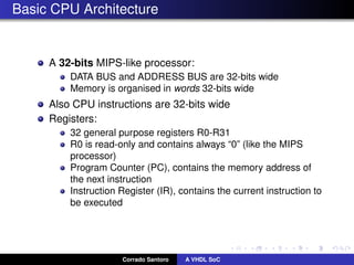
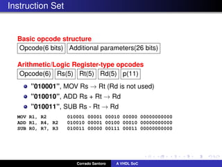


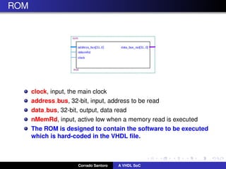


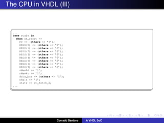


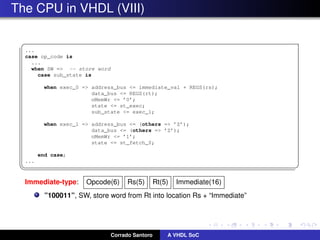


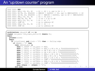


The document describes implementing a system-on-chip (SoC) using VHDL that includes a CPU, ROM, and parallel I/O port. The CPU is a 32-bit RISC architecture with 32 general purpose registers and instructions include MOV, ADD, SUB, LOAD, STORE. The ROM stores the program code. The parallel I/O port interfaces with external devices and responds to memory reads and writes. Implementation details are provided for each component in VHDL including register definitions, control signals, and finite state machines to describe operation.