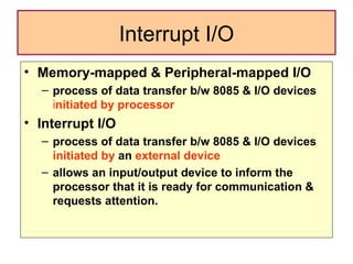
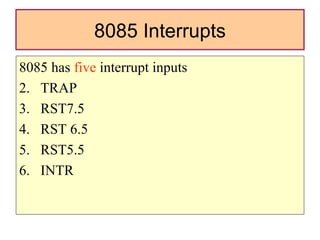
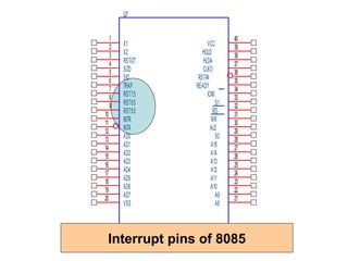
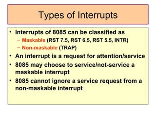
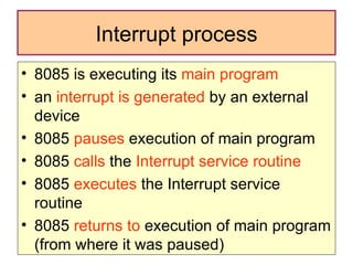
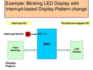
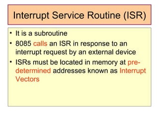
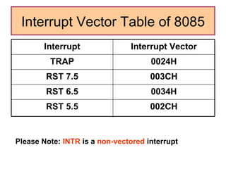
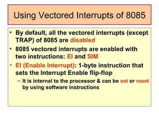
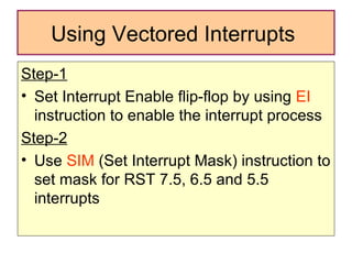
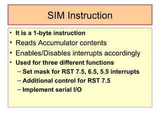
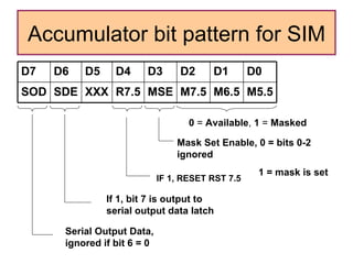
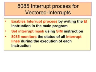
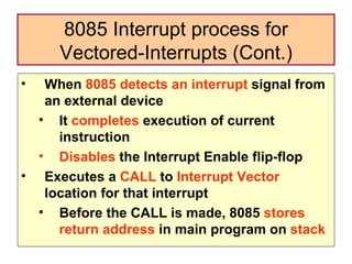
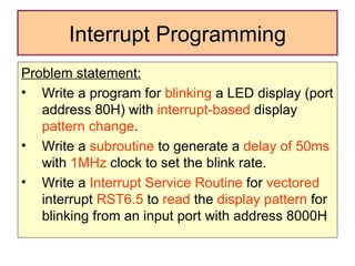
Interrupts of 8085
Interrupt I/O Memory-mapped & Peripheral-mapped I/O  process of data transfer b/w 8085 & I/O devices   i nitiated by processor Interrupt I/O  process of data transfer b/w 8085 & I/O devices  initiated by  an  external device  allows an input/output device to inform the processor that it is ready for communication & requests attention.
8085 Interrupts 8085 has  five  interrupt inputs TRAP RST7.5 RST 6.5 RST5.5 INTR
Interrupt pins of 8085
Types of Interrupts Interrupts of 8085 can be classified as  Maskable  (RST 7.5, RST 6.5, RST 5.5, INTR) Non-maskable  (TRAP) An interrupt is a request for attention/service 8085 may choose to service/not-service a maskable interrupt  8085 cannot ignore a service request from a non-maskable interrupt
Interrupt process 8085 is executing its  main program an  interrupt is generated  by an external device  8085  pauses  execution of main program 8085  calls  the  Interrupt service routine 8085  executes  the Interrupt service routine 8085  returns to  execution of main program (from where it was paused)
Example: Blinking LED Display with Interrupt-based Display-Pattern change  8085 Input Switches LED Display RST 7.5 (Display-Pattern ) Interrupt Switch Peripheral-mapped I/O Interrupt I/O
Interrupt Service Routine (ISR) It is a subroutine  8085  calls  an ISR in response to an interrupt request by an external device ISRs must be located in memory at  pre-determined  addresses known as  Interrupt Vectors
Interrupt Vector Table of 8085 Please Note:  INTR  is a  non-vectored  interrupt 002CH RST 5.5 0034H RST 6.5 003CH RST 7.5 0024H TRAP Interrupt Vector Interrupt
Using Vectored Interrupts of 8085 By default, all the vectored interrupts (except TRAP) of 8085 are  disabled   8085 vectored interrupts are enabled with two instructions:  EI  and  SIM EI (Enable Interrupt) : 1-byte instruction that sets the Interrupt Enable flip-flop  It is internal to the processor & can be  set  or  reset  by using software instructions
Using Vectored Interrupts  Step-1 Set Interrupt Enable flip-flop by using  EI  instruction to enable the interrupt process Step-2 Use  SIM  (Set Interrupt Mask) instruction to set mask for RST 7.5, 6.5 and 5.5 interrupts
SIM Instruction It is a 1-byte instruction Reads Accumulator contents Enables/Disables interrupts accordingly Used for three different functions Set mask for RST 7.5, 6.5, 5.5 interrupts Additional control for RST 7.5 Implement serial I/O
Accumulator bit pattern for SIM 0  =  Available ,  1  =  Masked Mask Set Enable, 0 = bits 0-2 ignored   1 = mask is set IF 1, RESET RST 7.5  If 1, bit 7 is output to serial output data latch Serial Output Data, ignored if bit 6 = 0 M5.5 M6.5 M7.5 MSE R7.5 XXX SDE SOD D0 D1 D2 D3 D4 D5 D6 D7
8085 Interrupt process for Vectored-Interrupts Enables Interrupt process  by writing the  EI  instruction in the main program Set interrupt mask  using  SIM  instruction 8085 monitors  the status of all  interrupt lines  during the execution of each instruction
When  8085 detects an interrupt  signal from an external device It  completes  execution of current instruction Disables  the Interrupt Enable flip-flop Executes a  CALL  to  Interrupt Vector  location for that interrupt Before the CALL is made, 8085  stores  return address  in main program on  stack 8085 Interrupt process for Vectored-Interrupts (Cont.)
8085  executes  the  ISR  written at the specified interrupt vector location ISR should include the EI instruction to  Enable Interrupt  again At the end of ISR,  RET  instruction transfers the program control back to the main program 8085 Interrupt process for Vectored-Interrupts (Cont.)
Interrupt Programming Problem statement: Write a program for  blinking  a LED display (port address 80H) with  interrupt-based  display  pattern change . Write a  subroutine  to generate a  delay of 50ms  with  1MHz  clock to set the blink rate.  Write a  Interrupt Service Routine  for  vectored  interrupt  RST6.5  to  read  the  display pattern  for blinking from an input port with address 8000H

1206 Interrupts Of 8085

  • 1.
  • 2.
    Interrupt I/O Memory-mapped& Peripheral-mapped I/O process of data transfer b/w 8085 & I/O devices i nitiated by processor Interrupt I/O process of data transfer b/w 8085 & I/O devices initiated by an external device allows an input/output device to inform the processor that it is ready for communication & requests attention.
  • 3.
    8085 Interrupts 8085has five interrupt inputs TRAP RST7.5 RST 6.5 RST5.5 INTR
  • 4.
  • 5.
    Types of InterruptsInterrupts of 8085 can be classified as Maskable (RST 7.5, RST 6.5, RST 5.5, INTR) Non-maskable (TRAP) An interrupt is a request for attention/service 8085 may choose to service/not-service a maskable interrupt 8085 cannot ignore a service request from a non-maskable interrupt
  • 6.
    Interrupt process 8085is executing its main program an interrupt is generated by an external device 8085 pauses execution of main program 8085 calls the Interrupt service routine 8085 executes the Interrupt service routine 8085 returns to execution of main program (from where it was paused)
  • 7.
    Example: Blinking LEDDisplay with Interrupt-based Display-Pattern change 8085 Input Switches LED Display RST 7.5 (Display-Pattern ) Interrupt Switch Peripheral-mapped I/O Interrupt I/O
  • 8.
    Interrupt Service Routine(ISR) It is a subroutine 8085 calls an ISR in response to an interrupt request by an external device ISRs must be located in memory at pre-determined addresses known as Interrupt Vectors
  • 9.
    Interrupt Vector Tableof 8085 Please Note: INTR is a non-vectored interrupt 002CH RST 5.5 0034H RST 6.5 003CH RST 7.5 0024H TRAP Interrupt Vector Interrupt
  • 10.
    Using Vectored Interruptsof 8085 By default, all the vectored interrupts (except TRAP) of 8085 are disabled 8085 vectored interrupts are enabled with two instructions: EI and SIM EI (Enable Interrupt) : 1-byte instruction that sets the Interrupt Enable flip-flop It is internal to the processor & can be set or reset by using software instructions
  • 11.
    Using Vectored Interrupts Step-1 Set Interrupt Enable flip-flop by using EI instruction to enable the interrupt process Step-2 Use SIM (Set Interrupt Mask) instruction to set mask for RST 7.5, 6.5 and 5.5 interrupts
  • 12.
    SIM Instruction Itis a 1-byte instruction Reads Accumulator contents Enables/Disables interrupts accordingly Used for three different functions Set mask for RST 7.5, 6.5, 5.5 interrupts Additional control for RST 7.5 Implement serial I/O
  • 13.
    Accumulator bit patternfor SIM 0 = Available , 1 = Masked Mask Set Enable, 0 = bits 0-2 ignored 1 = mask is set IF 1, RESET RST 7.5 If 1, bit 7 is output to serial output data latch Serial Output Data, ignored if bit 6 = 0 M5.5 M6.5 M7.5 MSE R7.5 XXX SDE SOD D0 D1 D2 D3 D4 D5 D6 D7
  • 14.
    8085 Interrupt processfor Vectored-Interrupts Enables Interrupt process by writing the EI instruction in the main program Set interrupt mask using SIM instruction 8085 monitors the status of all interrupt lines during the execution of each instruction
  • 15.
    When 8085detects an interrupt signal from an external device It completes execution of current instruction Disables the Interrupt Enable flip-flop Executes a CALL to Interrupt Vector location for that interrupt Before the CALL is made, 8085 stores return address in main program on stack 8085 Interrupt process for Vectored-Interrupts (Cont.)
  • 16.
    8085 executes the ISR written at the specified interrupt vector location ISR should include the EI instruction to Enable Interrupt again At the end of ISR, RET instruction transfers the program control back to the main program 8085 Interrupt process for Vectored-Interrupts (Cont.)
  • 17.
    Interrupt Programming Problemstatement: Write a program for blinking a LED display (port address 80H) with interrupt-based display pattern change . Write a subroutine to generate a delay of 50ms with 1MHz clock to set the blink rate. Write a Interrupt Service Routine for vectored interrupt RST6.5 to read the display pattern for blinking from an input port with address 8000H

Editor's Notes