The document describes VHDL code for 5 exercises:
1. Code to control 8 LEDs blinking in a circle.
2. Code for a down counter module from 8 to 0.
3. Code for a BCD down counter displaying on 7-segment LEDs from 59 to 00.
4. Code for a 1-of-16 decoder with enable.
5. Code for a JK flip-flop circuit and its testbench.
This document contains 18 VHDL code examples that implement various digital logic circuits including basic gates, full adders, multiplexers, flip-flops, counters, encoders, decoders, and a state machine. The examples range from simple combinational logic to more complex sequential circuits. Taken together, the document provides a overview of how to model fundamental building blocks of digital systems using VHDL.
This document describes a design for a counter seven segment display using an FPGA. The author implemented a counter component and a decoder component, then wired them together in a top-level systemSeg entity using port mapping. The counter counts from 0 to 9 and outputs a 4-bit binary coded decimal value. The decoder converts the 4-bit input to a 7-segment display output based on a case statement. The author notes that port mapping is useful for wiring components together in HDL and that designs need to be synchronous with a clock.
The document contains VHDL code for several basic digital logic components including a parallel-in parallel-out shift register, serial-in parallel-out shift register, 4-bit binary counter, 4-bit ring counter, RS latch, D latch, SR flip-flop, and D flip-flop. The code uses processes, signals, ports, and architectures to model the behavior and dataflow of each component.
This document describes a hardware design that includes components like a codec clock, PLL, and packet memory. It maps these components, describes signal connections between them, and includes processes for transferring data between the memory and codec. The design takes in audio data at 2.048 MHz, converts it to 75 MHz using a PLL, stores it in packet memory, and outputs it to a codec. It handles transferring 160 bytes per packet across two memory banks.
This document provides VHDL code for several digital logic circuits including decoders, counters, multiplexers and demultiplexers. It includes 4 sections: 1) decoder circuits for 2-to-4 and 3-to-8 decoding, 2) a 4-bit counter, 3) combinational logic circuits including decoders, encoders and a 74138 decoder, and 4) multiplexer circuits including 4-to-1 and 8-to-1 multiplexers and a 74151 demultiplexer. The VHDL code and test simulations are provided for each circuit.
The document describes a Universal Asynchronous Receiver Transmitter (UART) circuit. A UART allows a computer to communicate with external devices by transmitting serial data. It contains a receiver that takes in serial data and a transmitter that sends out serial data. A baud rate generator is used to synchronize the transmission and reception of bits. The document provides details on the UART components, data encoding, and includes VHDL code for a UART design.
Bcd counter with mode control & parallel load capabilityGaurang Rathod
This document describes the design and implementation of a BCD counter with mode control and parallel load capability using VHDL. It includes the entity and architecture of the counter using both behavioral and data flow methods. It also includes simulation waveforms, RTL schematics, and an application example of using an up-down counter for a semi-automated parking lot gate control system.
The document describes a digital clock design project implemented in VHDL. The clock displays hours and minutes in 24-hour format using 7-segment displays. Key components include a clockSecond module to generate clock pulses, a counter7seg module to count the time, an anodeController module to multiplex the displays, and a sevenSelect module to select the correct display digit based on the anode lines. The design was tested and able to correctly count and display the time in hours and minutes.
The document discusses VHDL including:
1. Keywords like entities, architectures, ports and components for building basic logic gates and a 2:1 multiplexer using structural, behavioral and test bench modeling.
2. Finite state machines including examples of Mealy and Moore models for asynchronous and synchronous state machines.
3. Generic clauses to customize delays in designs.
Digital to analog -Sqaure waveform generator in VHDLOmkar Rane
The document contains VHDL code for generating a square wave signal. It includes an entity that defines the ports and architecture for a square_wave module. The module uses a counter and flip-flop to toggle a signal on each clock cycle, producing a square wave output. A testbench is provided to simulate the module and check its output waveform.
The document describes the implementation of 16-bit and 64-bit shift registers using VHDL in data flow modeling. It includes the VHDL code, test bench, and simulation results for shift registers that shift the values in the input register right by 1 bit position on the positive edge of the clock. The 16-bit shift register outputs the shifted value on q1 and the 64-bit shift register outputs the shifted value on q2. The design and functionality of both shift registers are verified through simulation.
The document describes 8 experiments involving VHDL code implementations of various digital logic circuits. Experiment 1 implements 4:1 and 8:1 multiplexers. Experiment 2 implements 1:4 and 1:8 demultiplexers. Experiment 3 implements a 3:8 decoder. Experiment 4 implements a 4-bit adder. Experiment 5 implements a 4-bit comparator. Experiment 6 implements a 2-bit ALU. Experiment 7 and 8 both implement a D flip-flop. The document provides the full VHDL code for each circuit implementation.
The document describes the implementation of various digital logic circuits like D latch, D flip flop, JK flip flop, multiplexers, decoders, counters etc. using VHDL. It includes the VHDL code, test benches and synthesis reports for each circuit. The aim is to design the circuits in behavioral and structural modeling and verify their functionality.
The document describes a VHDL implementation of a 2-digit countdown timer using Aldec HDL and a Basys2 kit. It includes the VHDL code for the timer modules: clockSecond generates the clock signal, counter7seg controls the counting, binary7decoder decodes the digits to 7-segment displays, and sevenSelect multiplexes which digit is displayed. The top-level diagram shows how the modules are connected to implement the 2-digit timer functionality.
The document contains code for several basic digital logic components including:
1. A full adder described using signals and delays.
2. A 4:1 multiplexer using elsif statements to select the output.
3. A 4:1 multiplexer using a when statement to select the output.
4. A 1:4 demultiplexer using if/elsif statements to activate one output.
5. A full adder described behaviorally using boolean expressions.
6. A D latch with an output that follows the input on the positive clock edge.
7. A D flip-flop with an output that follows the input on the positive clock edge.
The document describes the design and implementation of a seven segment counter on an FPGA. It includes the implementation of a prescaler, debouncing circuit, binary coded decimal (BCD) counter, and seven segment decoder. The prescaler was initially generating a warning about excessive skew, which was resolved by adding a clock buffer to the prescaler output. The design components are instantiated and connected in the top level system counter entity.
32 bit ALU Chip Design using IBM 130nm process technologyBharat Biyani
- Implemented a 32 bit Arithmetic/Logic unit in VHDL using behavioral Modeling which involves all basic ALU operations including special functionality like binary-to-grey code conversion, parity check, sum of first N numbers. Simulation is performed in ModelSim IDE.
- Involved design using Cadence (Virtuoso Layout/Schematic) and Hspice simulation of standard library cell.
- Involved library characterization using NCX, RTL synthesis of VHDL code using Synopsys Design Vision, auto placement & routing using Encounter, static timing analysis using Synopsys Primetime.
The document describes processes in VHDL. It defines a process as a concurrent statement that contains sequential logic. Processes run in parallel and can be conditioned by a sensitivity list or wait statement. Local variables retain their values between executions. It provides an example of a process with a sensitivity list and one with a wait statement. It also summarizes the general structure of a VHDL program and describes different types of process control including if-then-else, case statements, and decoders. Additional topics covered include flip-flops, counters, and finite state machines.
The document describes data flow modeling in VHDL. It discusses how data flow style architecture models hardware in terms of the movement of data over continuous time between combinational logic components. It also describes how concurrent signal assignment statements can be used to model simple combinational logic. Examples provided include half adder, full adder, comparator, multiplexer, decoder, and arithmetic logic unit designs modeled using data flow style and concurrent signal assignments.
This document describes a UART transmitter design using VHDL. It includes the entity declaration for the UART transmitter with ports, and the architecture with two processes - one for control signal generation and state machine, and another for sequential logic and register updates. The design transmits serial data on a single output line by shifting out bits from a 9-bit transmit shift register synchronized to a baud clock.
This document describes a VLSI design project to implement pipeline stalling using VHDL. It includes modules for registers, multiplexers, an ALU, and a pipelined multiplier. The coding technique uses registers to move data between pipeline stages on a common clock. Simulation waveforms show the pipeline functioning as intended. Pipelining is commonly used to increase throughput in multicore computers, operating system design, superscalar processors, and firmware.
The document describes interfacing an FPGA to an LCD 16x2 display. It includes a block diagram, pin descriptions, timing diagrams, LCD initialization procedures from the datasheet, and VHDL code to implement the LCD controller on the FPGA. The VHDL code uses a state machine and ROM-based model with an 8-bit data line to generate the LCD initialization sequence and display text on the LCD. Behavioral and post-route simulations are shown to verify the design works as intended.
This VHDL code defines a counter (CONT) with a 7-segment display output (S). The counter increments or decrements depending on the signal UP. It resets to 0 when the reset signal is asserted or reaches the maximum value of 7. The counter value is displayed on the 7-segment output according to the defined truth table.
This document discusses sequential circuits in VHDL. It begins by defining sequential circuits as circuits that perform computations over multiple clock cycles by storing intermediate results in memory registers. It then explains how to write sequential logic in VHDL using process statements. Several examples of basic sequential elements like D flip-flops with and without resets are described. The document concludes by providing references for further reading on VHDL and digital design.
This document describes a student project to build a washing machine prototype. It includes a summary, instruction manual, state diagrams, schematics and code for the washing machine. The prototype has two modes - manual, where the user selects the function, or automatic, where it runs through the cycle automatically. It was built using multiplexers, Moore state machines, registers and other components on a Xilinx Basys 2 board. The code provided includes modules for functions like filling, washing, draining and spinning in manual mode.
This document contains VHDL code for multiplexer circuits and corrections for exercises on VHDL code. It includes:
1. Four ways to write VHDL code for a 2-to-1 multiplexer using different assignment methods.
2. Corrections for an exercise involving VHDL code for a circuit with 4 inputs and 2 outputs based on different input patterns.
3. The corrections provide 4 different ways to write the VHDL code using selective assignment, conditional assignment, if-then-else structure, and case-when structure.
4. VHDL code for a simple circuit with 2 inputs, 1 select line, and 1 output using an if-then process.
Instagram has become one of the most popular social media platforms, allowing people to share photos, videos, and stories with their followers. Sometimes, though, you might want to view someone's story without them knowing.
Gen Z and the marketplaces - let's translate their needsLaura Szabó
The product workshop focused on exploring the requirements of Generation Z in relation to marketplace dynamics. We delved into their specific needs, examined the specifics in their shopping preferences, and analyzed their preferred methods for accessing information and making purchases within a marketplace. Through the study of real-life cases , we tried to gain valuable insights into enhancing the marketplace experience for Generation Z.
The workshop was held on the DMA Conference in Vienna June 2024.
Discover the benefits of outsourcing SEO to Indiadavidjhones387
"Discover the benefits of outsourcing SEO to India! From cost-effective services and expert professionals to round-the-clock work advantages, learn how your business can achieve digital success with Indian SEO solutions.
Understanding User Behavior with Google Analytics.pdfSEO Article Boost
Unlocking the full potential of Google Analytics is crucial for understanding and optimizing your website’s performance. This guide dives deep into the essential aspects of Google Analytics, from analyzing traffic sources to understanding user demographics and tracking user engagement.
Traffic Sources Analysis:
Discover where your website traffic originates. By examining the Acquisition section, you can identify whether visitors come from organic search, paid campaigns, direct visits, social media, or referral links. This knowledge helps in refining marketing strategies and optimizing resource allocation.
User Demographics Insights:
Gain a comprehensive view of your audience by exploring demographic data in the Audience section. Understand age, gender, and interests to tailor your marketing strategies effectively. Leverage this information to create personalized content and improve user engagement and conversion rates.
Tracking User Engagement:
Learn how to measure user interaction with your site through key metrics like bounce rate, average session duration, and pages per session. Enhance user experience by analyzing engagement metrics and implementing strategies to keep visitors engaged.
Conversion Rate Optimization:
Understand the importance of conversion rates and how to track them using Google Analytics. Set up Goals, analyze conversion funnels, segment your audience, and employ A/B testing to optimize your website for higher conversions. Utilize ecommerce tracking and multi-channel funnels for a detailed view of your sales performance and marketing channel contributions.
Custom Reports and Dashboards:
Create custom reports and dashboards to visualize and interpret data relevant to your business goals. Use advanced filters, segments, and visualization options to gain deeper insights. Incorporate custom dimensions and metrics for tailored data analysis. Integrate external data sources to enrich your analytics and make well-informed decisions.
This guide is designed to help you harness the power of Google Analytics for making data-driven decisions that enhance website performance and achieve your digital marketing objectives. Whether you are looking to improve SEO, refine your social media strategy, or boost conversion rates, understanding and utilizing Google Analytics is essential for your success.
Meet up Milano 14 _ Axpo Italia_ Migration from Mule3 (On-prem) to.pdfFlorence Consulting
Quattordicesimo Meetup di Milano, tenutosi a Milano il 23 Maggio 2024 dalle ore 17:00 alle ore 18:30 in presenza e da remoto.
Abbiamo parlato di come Axpo Italia S.p.A. ha ridotto il technical debt migrando le proprie APIs da Mule 3.9 a Mule 4.4 passando anche da on-premises a CloudHub 1.0.
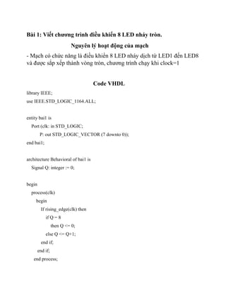
1. Bài 1: Viết chương trình điều khiển 8 LED nháy tròn.
Nguyên lý hoạt động của mạch
- Mạch có chức năng là điều khiển 8 LED nháy dịch từ LED1 đến LED8
và được sắp xếp thành vòng tròn, chương trình chạy khi clock=1
Code VHDL
library IEEE;
use IEEE.STD_LOGIC_1164.ALL;
entity bai1 is
Port (clk: in STD_LOGIC;
P: out STD_LOGIC_VECTOR (7 downto 0));
end bai1;
architecture Behavioral of bai1 is
Signal Q: integer := 0;
begin
process(clk)
begin
If rising_edge(clk) then
if Q = 8
then Q <= 0;
else Q <= Q+1;
end if;
end if;
end process;
2. process(Q)
begin
case Q is
when 0 => P <= "00000000";
when 1 => P <= "10000000";
when 2 => P <= "01000000";
when 3 => P <= "00100000";
when 4 => P <= "00010000";
when 5 => P <= "00001000";
when 6 => P <= "00000100";
when 7 => P <= "00000010";
when 8 => P <= "00000001";
when others => P <= "00000000";
end case;
end process;
end Behavioral;
Test bench
library IEEE;
use IEEE.STD_LOGIC_1164.ALL;
use IEEE.STD_LOGIC_UNSIGNED.ALL;
entity test is
end test;
architecture Behavioral of test is
Component Bai1 is
Port ( clk : in STD_LOGIC;
P : out STD_LOGIC_VECTOR (7 downto 0)
);
3. end Component;
Signal clk: STD_LOGIC := '0';
Signal P: STD_LOGIC_VECTOR(7 downto 0);
begin
VVT: Bai1 Port map(
CLK => CLK,
P => P
);
CLK <= not CLK after 10 ns;
end Behavioral;
Bài 2: Viết chương trình mô tả bộ đếm lùi Mod 9 (có CLK, CLR,
Pause)
Nguyên lí hoạt động của mạch
- Mạch đếm lùi mode 9 có clock, clear và pause. Mạch thực hiện đếm
từ 8 về 0,chương trình hoạt động khi clock=1 , khi clear=1 chương
trình trở về trạng thái reset là bằng “0000” rồi tiếp tục đếm từ 8 về 0
Code VHDL
library IEEE;
use IEEE.STD_LOGIC_1164.ALL;
use IEEE.STD_LOGIC_ARITH.ALL;
use IEEE.STD_LOGIC_UNSIGNED.ALL;
entity bai2 is
port (CLK: in std_logic;
CLR: in std_logic;
PAUSE: in std_logic;
count: out std_logic_vector(3 downto 0));
4. end bai2;
architecture Behavioral of bai2 is
Signal counter: std_logic_vector(3 downto 0) := "1000";
begin
process (CLK, CLR, PAUSE)
begin
if CLR = '1' then counter <= "0000";
end if;
if rising_edge(CLK) and CLR = '0' and PAUSE = '0' then
if (counter = "0000") then
counter <= "1000";
else counter <= counter - 1;
end if;
end if;
end process;
count <= counter;
end Behavioral;
Test bench
library IEEE;
use IEEE.STD_LOGIC_1164.ALL;
use IEEE.STD_LOGIC_ARITH.ALL;
use IEEE.STD_LOGIC_UNSIGNED.ALL;
entity test is
end test;
5. architecture Behavioral of test is
component bai2 is
port ( CLK : in std_logic;
CLR : in std_logic;
PAUSE : in std_logic;
count : out std_logic_vector(3 downto 0));
end component;
signal CLK,CLR,PAUSE: std_logic := '0';
signal count: std_logic_vector(3 downto 0);
begin
uut: bai2 port map(
CLK => CLK,
CLR => CLR,
PAUSE => PAUSE,
count => count
);
CLK <= not CLK after 10ns ;
pausess: process
begin
PAUSE <= '0'; wait for 500ns;
PAUSE <= '1'; wait for 80ns;
end process;
clearr: process
begin
CLR <= '0'; wait for 700ns;
CLR <= '1'; wait for 10ns;
6. end process;
end Behavioral;
Bài 3 : Viết chương trình mô tả bộ đếm lùi BCD từ 59 đến 00 - hiển
thị trên LED 7 đoạn Anode chung (CLK, CLR)
Nguyên lí của mạch
- Bộ đếm lùi BCD mod 60 đếm lùi từ 59 về 00 và hiển thị trên LED 7
đoạn Anode chung có xung clock và clear. Khởi tạo giá trị ban đầu 2
biến hàng chục và hàng đơn vị bằng 59 và cho chạy dần về 00. Mạch bắt
đầu đếm khi clock = 1, khi clear = 1 mạch trở về trạng thái reset là
“0000” rồi bắt đầu đếm lại từ 59 về 00
Code VHDL
library IEEE;
use IEEE.STD_LOGIC_1164.ALL;
use IEEE.STD_LOGIC_UNSIGNED.ALL;
entity Bai3 is
Port (CLK: in STD_LOGIC;
CLR: in STD_LOGIC;
Led1: out STD_LOGIC_VECTOR (6 downto 0);
Led2: out STD_LOGIC_VECTOR (6 downto 0);
OutChuc: out STD_LOGIC_VECTOR(3 downto 0);
OutDvi: Out STD_LOGIC_VECTOR(3 downto 0));
end Bai3;
7. architecture Behavioral of Bai3 is
Signal Chuc: STD_LOGIC_VECTOR(3 downto 0) := "0101";
Signal Dvi: STD_LOGIC_VECTOR(3 downto 0) := "1001";
begin
process (CLK, CLR)
begin
if CLR = '1' then
Chuc <= "0000";
Dvi <= "0000";
elsif CLK'event and CLK = '1' then
if (Dvi = "0000") then
Dvi <= "1001";
if Chuc = "0000" then
Chuc <= "0101";
else Chuc <= Chuc - 1;
end if;
else Dvi <= Dvi - 1;
end if;
end if;
end process;
OutChuc <= Chuc;
OutDvi <= Dvi;
--Hien thi led
process(Dvi)
begin
case Dvi is
when x"9" => Led1 <= "0010000";
when x"8" => Led1 <= "0000000";
when x"7" => Led1 <= "1111000";
when x"6" => Led1 <= "0000010";
when x"5" => Led1 <= "0010010";
8. when x"4" => Led1 <= "0011001";
when x"3" => Led1 <= "0110000";
when x"2" => Led1 <= "0100100";
when x"1" => Led1 <= "1111001";
when others => null;
end case;
end process;
process(Chuc)
begin
case Chuc is
when x"5" => Led2 <= "0010010";
when x"4" => Led2 <= "0011001";
when x"3" => Led2 <= "0110000";
when x"2" => Led2 <= "0100100";
when x"1" => Led2 <= "1111001";
when others => null;
end case;
end process;
end Behavioral;
Test bench
library IEEE;
use IEEE.STD_LOGIC_1164.ALL;
use IEEE.STD_LOGIC_ARITH.ALL;
use IEEE.STD_LOGIC_UNSIGNED.ALL;
entity bai3comp is
end bai3comp;
architecture Behavioral of bai3comp is
9. component bai3code is
Port ( CLK : in STD_LOGIC;
CLR : in STD_LOGIC;
Led1 : out STD_LOGIC_VECTOR (6 downto 0);
Led2 : out STD_LOGIC_VECTOR (6 downto 0);
OutChuc: out STD_LOGIC_VECTOR(3 downto 0);
OutDvi : out STD_LOGIC_VECTOR(3 downto 0));
end component;
Signal CLK, CLR: STD_LOGIC := '0';
Signal Led1, Led2: STD_LOGIC_VECTOR(6 downto 0);
Signal OutChuc: STD_LOGIC_VECTOR(3 downto 0);
Signal OutDvi: STD_LOGIC_VECTOR(3 downto 0);
begin
MDH: bai3code port map(
CLK => CLK,
CLR => CLR,
Led1 => Led1,
Led2 => Led2,
OutChuc => OutChuc,
OutDvi => OutDvi
);
CLK <= not CLK after 10ns;
clear: process
begin
CLR <= '0'; wait for 500ns;
CLR <= '1'; wait for 80ns;
end process;
end Behavioral;
10. Bài 4: Viết chương trình mô tả bộ phân kênh 1:16 (Enable hoạt
động ở mức thấp)
Nguyên lý hoạt động
Bộ phân kênh 1 đầu vào 16 đầu ra, sử dụng Sel 4 bit thay đổi liên tục
16 trạng thái. Khi enable = 0 ứng với mỗi trạng thái Sel tại mỗi thời
điểm sẽ làm thay đổi đầu ra tương ứng. Khi enable = 1 toàn bộ đầu
ra bằng 0.
Code VHDL
library IEEE;
use IEEE.STD_LOGIC_1164.ALL;
use IEEE.STD_LOGIC_ARITH.ALL;
use IEEE.STD_LOGIC_UNSIGNED.ALL;
entity bai4 is
Port (
Enable : in STD_LOGIC;
Sel : in STD_LOGIC_VECTOR(3 downto 0);
Din : in STD_LOGIC;
OutData : out STD_LOGIC_VECTOR (15 downto 0));
end bai4;
architecture Behavioral of bai4 is
Signal OutPut: STD_LOGIC_VECTOR(15 downto 0) := "0000000000000000";
begin
process(Sel, Enable, Din)
begin
OutPut <= "0000000000000000";
11. if Enable = '0' then
Case Sel is
when "0000" => OutPut(0) <= Din;
when "0001" => OutPut(1) <= Din;
when "0010" => OutPut(2) <= Din;
when "0011" => OutPut(3) <= Din;
when "0100" => OutPut(4) <= Din;
when "0101" => OutPut(5) <= Din;
when "0110" => OutPut(6) <= Din;
when "0111" => OutPut(7) <= Din;
when "1000" => OutPut(8) <= Din;
when "1001" => OutPut(9) <= Din;
when "1010" => OutPut(10) <= Din;
when "1011" => OutPut(11) <= Din;
when "1100" => OutPut(12) <= Din;
when "1101" => OutPut(13) <= Din;
when "1110" => OutPut(14) <= Din;
when others => OutPut(15) <= Din;
end case;
end if;
end process;
OutData <= OutPut;
end Behavioral;
Testbench
library IEEE;
use IEEE.STD_LOGIC_1164.ALL;
use IEEE.STD_LOGIC_ARITH.ALL;
use IEEE.STD_LOGIC_UNSIGNED.ALL;
entity test is
12. end test;
architecture Behavioral of test is
component main is
Port (
Enable : in STD_LOGIC;
Sel : in STD_LOGIC_VECTOR(3 downto 0);
Din : in STD_LOGIC;
OutData : out STD_LOGIC_VECTOR (15 downto 0));
end component;
Signal Enable, Din : STD_LOGIC :='0';
Signal Sel : STD_LOGIC_VECTOR(3 downto 0) := "0000";
Signal OutData : STD_LOGIC_VECTOR(15 downto 0);
begin
uut: main port map(
Enable => Enable,
Sel => Sel,
Din => Din,
OutData => OutData
);
Enable <= not Enable after 200ns;
Din <= not Din after 50ns;
process
begin
Sel <= "0000";
for i in 0 to 15 loop
wait for 10ns;
Sel <= Sel + 1;
end loop;
end process;
13. end Behavioral;
Bài 5 : Viết mô tả VHDL (Entity và Architecture) cho mạch đó. Viết
testbench để kiểm tra hoạt động của mạch.
Code VHDL
library IEEE;
use IEEE.STD_LOGIC_1164.ALL;
entity bai5 is
Port
(
CLK : in STD_LOGIC;
X : in STD_LOGIC;
Z : out STD_LOGIC
);
end bai5;
architecture Behavioral of bai5 is
component JKFF is
Port
(
CLK: in STD_LOGIC;
J : in STD_LOGIC;
K : in STD_LOGIC;
Q : out STD_LOGIC;
QN : out STD_LOGIC
);
end component;
----------------------------------------
14. signal j0_data : std_logic;
signal k0_data : std_logic;
signal q0_data : std_logic;
signal q0n_data : std_logic;
signal k1_data : std_logic;
signal q1_data : std_logic;
signal q1n_data : std_logic;
begin
j0_data <= q1n_data and X;
k0_data <= q1_data xor X;
k1_data <= q0n_data nand X;
Z <= q0_data and q1_data and X;
JKFF_INST0: JKFF
Port map
(
CLK => CLK,
J => j0_data,
K => k0_data,
Q => q0_data,
QN => q0n_data
);
JKFF_INST1: JKFF
Port map
(
CLK => CLK,
15. J => q0_data,
K => k1_data,
Q => q1_data,
QN => q1n_data
);
end Behavioral;
Test bench
LIBRARY ieee;
USE ieee.std_logic_1164.ALL;
ENTITY Test_bench IS
END Test_bench;
ARCHITECTURE behavior OF Test_bench IS
-- Component Declaration for the Unit Under Test (UUT)
COMPONENT Bai5
PORT(
CLK : IN std_logic;
X : IN std_logic;
Z : OUT std_logic
);
END COMPONENT;
--Inputs
signal CLK : std_logic := '0';
16. signal X : std_logic := '0';
--Outputs
signal Z : std_logic;
-- Clock period definitions
-- constant CLK_period : time := 20 ns;
BEGIN
-- Instantiate the Unit Under Test (UUT)
uut: Bai5
PORT MAP
(
CLK => CLK,
X => X,
Z => Z
);
-- Clock process definitions
CLK_process :process
begin
CLK <= '0';
wait for 10 ns;
CLK <= '1';
wait for 10 ns;
end process;
-- Stimulus process
stim_proc: process
17. begin
-- hold reset state for 100 ns.
wait until rising_edge(CLK);
X <= '0';
wait until rising_edge(CLK);
X <= '0';
wait until rising_edge(CLK);
X <= '0';
--000
wait until rising_edge(CLK);
X <= '0';
wait until rising_edge(CLK);
X <= '0';
wait until rising_edge(CLK);
X <= '1';
--001
wait until rising_edge(CLK);
X <= '0';
wait until rising_edge(CLK);
X <= '1';
wait until rising_edge(CLK);
X <= '1';
--010
wait until rising_edge(CLK);
X <= '0';
wait until rising_edge(CLK);
X <= '1';
wait until rising_edge(CLK);
X <= '0';
-- 011
wait until rising_edge(CLK);
18. X <= '0';
wait until rising_edge(CLK);
X <= '1';
wait until rising_edge(CLK);
X <= '1';
--100
wait until rising_edge(CLK);
X <= '1';
wait until rising_edge(CLK);
X <= '0';
wait until rising_edge(CLK);
X <= '0';
--101
wait until rising_edge(CLK);
X <= '1';
wait until rising_edge(CLK);
X <= '0';
wait until rising_edge(CLK);
X <= '1';
--110
wait until rising_edge(CLK);
X <= '1';
wait until rising_edge(CLK);
X <= '1';
wait until rising_edge(CLK);
X <= '1';
-- insert stimulus here
end process;
END;