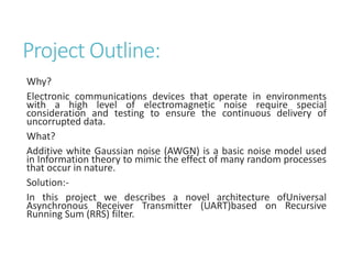
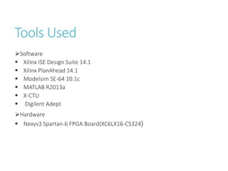
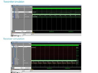
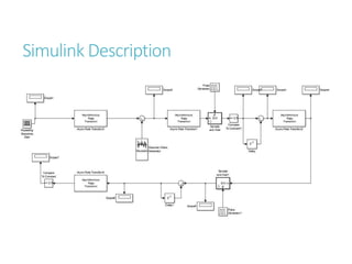
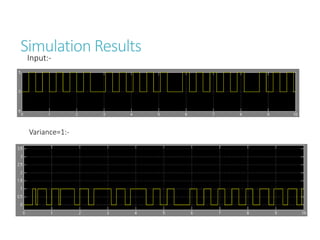
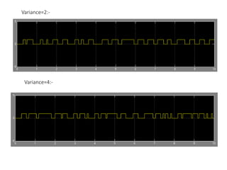
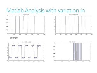
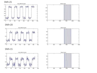
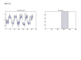
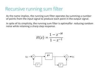
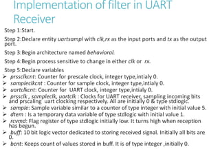
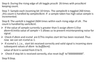
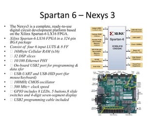
This document describes a project to design a robust UART architecture using a recursive running sum filter for better noise performance. It discusses adding noise to communication channels to test noise performance. It then describes implementing a UART receiver using a recursive running sum filter to reduce noise while maintaining signal integrity. The UART design is tested on a Nexys3 Spartan-6 FPGA board in Xilinx ISE using VHDL. Simulation results at different noise levels show the filter is effective at reducing noise.

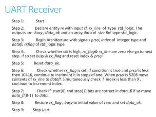


![Multiband Transceivers - [Chapter 4] Design Parameters of Wireless Radios](https://cdn.slidesharecdn.com/ss_thumbnails/ch4-150613070934-lva1-app6892-thumbnail.jpg?width=640&height=640&fit=bounds)

![[DCG 25] Александр Большев - Never Trust Your Inputs or How To Fool an ADC](https://cdn.slidesharecdn.com/ss_thumbnails/presentationdefconrussia-160406215741-thumbnail.jpg?width=640&height=640&fit=bounds)


![RF Module Design - [Chapter 4] Transceiver Architecture](https://cdn.slidesharecdn.com/ss_thumbnails/rfch4-150613070346-lva1-app6891-thumbnail.jpg?width=640&height=640&fit=bounds)