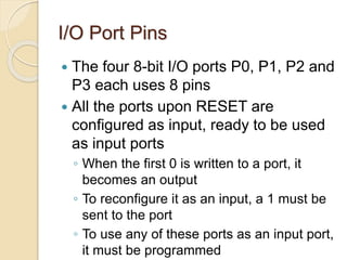
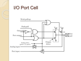
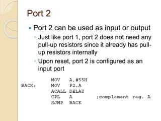
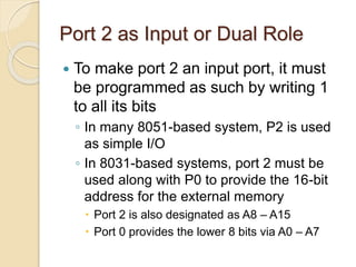
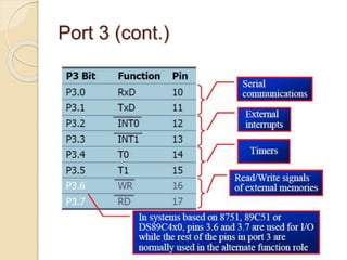
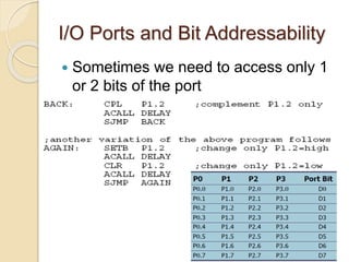
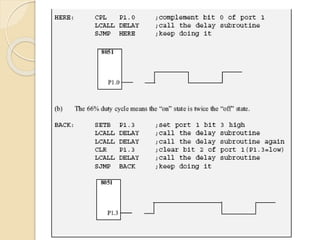
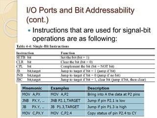
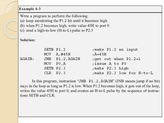
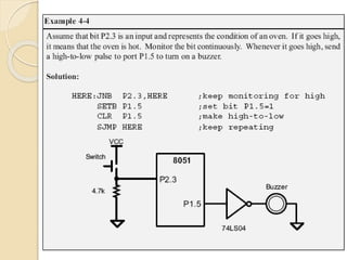
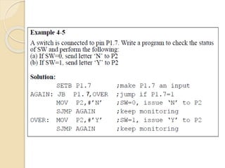
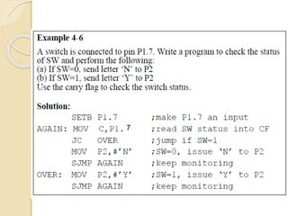
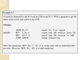
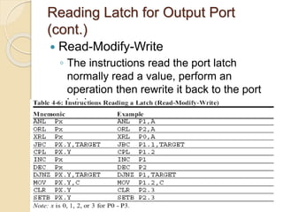
I/O PORT
PROGRAMMING
by
E.M.Roopa Devi
Kongu Engineering College
I/O Port Pins
 The four 8-bit I/O ports P0, P1, P2 and
P3 each uses 8 pins
 All the ports upon RESET are
configured as input, ready to be used
as input ports
◦ When the first 0 is written to a port, it
becomes an output
◦ To reconfigure it as an input, a 1 must be
sent to the port
◦ To use any of these ports as an input port,
it must be programmed
Pin 29 (PSEN): This pin is used to enable external program memory.
If we use an external ROM for storing the program, then logic 0
appears on it, which indicates Micro controller to read data from the
memory.
Port 0
 It can be used for input or output
◦ Each pin must be connected externally to
a 10K ohm pull-up resistor
 This is due to the fact that P0 is an open drain,
unlike P1, P2, and P3
 Open drain is a term used for MOS chips in the same
way that open collector is used for TTL chips
Port 0 (cont.)
Port 0 as Input
 In order to make port 0 an input, the
port must be programmed by writing 1
to all the bits
I/O Port Cell
Dual Role of Port 0
 Port 0 is also designated as AD0-AD7
◦ Allowing it to be used for both address
and data
◦ When connecting an 8051/31 to an
external memory, port 0 provides both
address and data
Port 1
 Port 1 can be used as input or output
◦ In contrast to port 0, this port does not
need any pull-up resistors since it already
has pull-up resistors internally
◦ Upon reset, port 1 is configured as an
input port
Port 1 as Input
 To make port 1 an input port, it must
be programmed as such by writing 1
to all its bits
Port 2
 Port 2 can be used as input or output
◦ Just like port 1, port 2 does not need any
pull-up resistors since it already has pull-
up resistors internally
◦ Upon reset, port 2 is configured as an
input port
Port 2 as Input or Dual Role
 To make port 2 an input port, it must
be programmed as such by writing 1
to all its bits
◦ In many 8051-based system, P2 is used
as simple I/O
◦ In 8031-based systems, port 2 must be
used along with P0 to provide the 16-bit
address for the external memory
 Port 2 is also designated as A8 – A15
 Port 0 provides the lower 8 bits via A0 – A7
Port 3
 Port 3 can be used as input or output
◦ Port 3 does not need any pull-up resistors
◦ Port 3 is configured as an input port upon
reset
 This is not the way it is most commonly used
 Port 3 has the additional function of
providing some extremely important
signals
Port 3 (cont.)
Different ways of Accessing
Entire 8 Bits
I/O Ports and Bit Addressability
 Sometimes we need to access only 1
or 2 bits of the port
I/O Ports and Bit Addressability
(cont.)
 Instructions that are used for signal-bit
operations are as following:
Checking an Input Bit
 The JNB and JB instructions are
widely used single-bit operations
◦ They allow you to monitor a bit and make
a decision depending on whether it’s 0 or
1
◦ These two instructions can be used for
any bits of I/O ports 0, 1, 2, and 3
◦ Port 3 is typically not used for any I/O,
either single-bit or byte-wise
7
7
0 0
Reading Input Pins vs. Port
Latch
 In reading a port
◦ Some instructions read the status of port
pins
◦ Others read the status of an internal port
latch
◦ When reading ports there are two
possibilities:
 Read the status of the input pin
 Read the internal latch of the output port
 Confusion between them is a major source of errors in
8051 programming
 Especially where external hardware is concerned
Reading Latch for Output Port
 Some instructions read the contents of
an internal port latch instead of
reading the status of an external pin
◦ For example, look at the ANL P1,A
instruction and the sequence of actions is:
 It reads the internal latch of the port and brings
that data into the CPU
 This data is ANDed with the contents of register
A
 The result is rewritten back to the port latch
 The port pin data is changed and now has the
same value as port latch
Reading Latch for Output Port
(cont.)
 Read-Modify-Write
◦ The instructions read the port latch
normally read a value, perform an
operation then rewrite it back to the port
latch
Read-modify-write Feature
 The ports in 8051 can be accessed by
the Read-modify-write technique
◦ This feature saves many lines of code by
combining in a single instruction all three
actions
 Reading the port
 Modifying it
 Writing to the port

I/O port programming in 8051

  • 1.
  • 2.
    I/O Port Pins The four 8-bit I/O ports P0, P1, P2 and P3 each uses 8 pins  All the ports upon RESET are configured as input, ready to be used as input ports ◦ When the first 0 is written to a port, it becomes an output ◦ To reconfigure it as an input, a 1 must be sent to the port ◦ To use any of these ports as an input port, it must be programmed
  • 4.
    Pin 29 (PSEN):This pin is used to enable external program memory. If we use an external ROM for storing the program, then logic 0 appears on it, which indicates Micro controller to read data from the memory.
  • 5.
    Port 0  Itcan be used for input or output ◦ Each pin must be connected externally to a 10K ohm pull-up resistor  This is due to the fact that P0 is an open drain, unlike P1, P2, and P3  Open drain is a term used for MOS chips in the same way that open collector is used for TTL chips
  • 6.
  • 7.
    Port 0 asInput  In order to make port 0 an input, the port must be programmed by writing 1 to all the bits
  • 8.
  • 9.
    Dual Role ofPort 0  Port 0 is also designated as AD0-AD7 ◦ Allowing it to be used for both address and data ◦ When connecting an 8051/31 to an external memory, port 0 provides both address and data
  • 10.
    Port 1  Port1 can be used as input or output ◦ In contrast to port 0, this port does not need any pull-up resistors since it already has pull-up resistors internally ◦ Upon reset, port 1 is configured as an input port
  • 11.
    Port 1 asInput  To make port 1 an input port, it must be programmed as such by writing 1 to all its bits
  • 12.
    Port 2  Port2 can be used as input or output ◦ Just like port 1, port 2 does not need any pull-up resistors since it already has pull- up resistors internally ◦ Upon reset, port 2 is configured as an input port
  • 13.
    Port 2 asInput or Dual Role  To make port 2 an input port, it must be programmed as such by writing 1 to all its bits ◦ In many 8051-based system, P2 is used as simple I/O ◦ In 8031-based systems, port 2 must be used along with P0 to provide the 16-bit address for the external memory  Port 2 is also designated as A8 – A15  Port 0 provides the lower 8 bits via A0 – A7
  • 14.
    Port 3  Port3 can be used as input or output ◦ Port 3 does not need any pull-up resistors ◦ Port 3 is configured as an input port upon reset  This is not the way it is most commonly used  Port 3 has the additional function of providing some extremely important signals
  • 15.
  • 17.
    Different ways ofAccessing Entire 8 Bits
  • 18.
    I/O Ports andBit Addressability  Sometimes we need to access only 1 or 2 bits of the port
  • 21.
    I/O Ports andBit Addressability (cont.)  Instructions that are used for signal-bit operations are as following:
  • 22.
    Checking an InputBit  The JNB and JB instructions are widely used single-bit operations ◦ They allow you to monitor a bit and make a decision depending on whether it’s 0 or 1 ◦ These two instructions can be used for any bits of I/O ports 0, 1, 2, and 3 ◦ Port 3 is typically not used for any I/O, either single-bit or byte-wise
  • 25.
  • 26.
  • 27.
  • 28.
    Reading Input Pinsvs. Port Latch  In reading a port ◦ Some instructions read the status of port pins ◦ Others read the status of an internal port latch ◦ When reading ports there are two possibilities:  Read the status of the input pin  Read the internal latch of the output port  Confusion between them is a major source of errors in 8051 programming  Especially where external hardware is concerned
  • 29.
    Reading Latch forOutput Port  Some instructions read the contents of an internal port latch instead of reading the status of an external pin ◦ For example, look at the ANL P1,A instruction and the sequence of actions is:  It reads the internal latch of the port and brings that data into the CPU  This data is ANDed with the contents of register A  The result is rewritten back to the port latch  The port pin data is changed and now has the same value as port latch
  • 30.
    Reading Latch forOutput Port (cont.)  Read-Modify-Write ◦ The instructions read the port latch normally read a value, perform an operation then rewrite it back to the port latch
  • 31.
    Read-modify-write Feature  Theports in 8051 can be accessed by the Read-modify-write technique ◦ This feature saves many lines of code by combining in a single instruction all three actions  Reading the port  Modifying it  Writing to the port