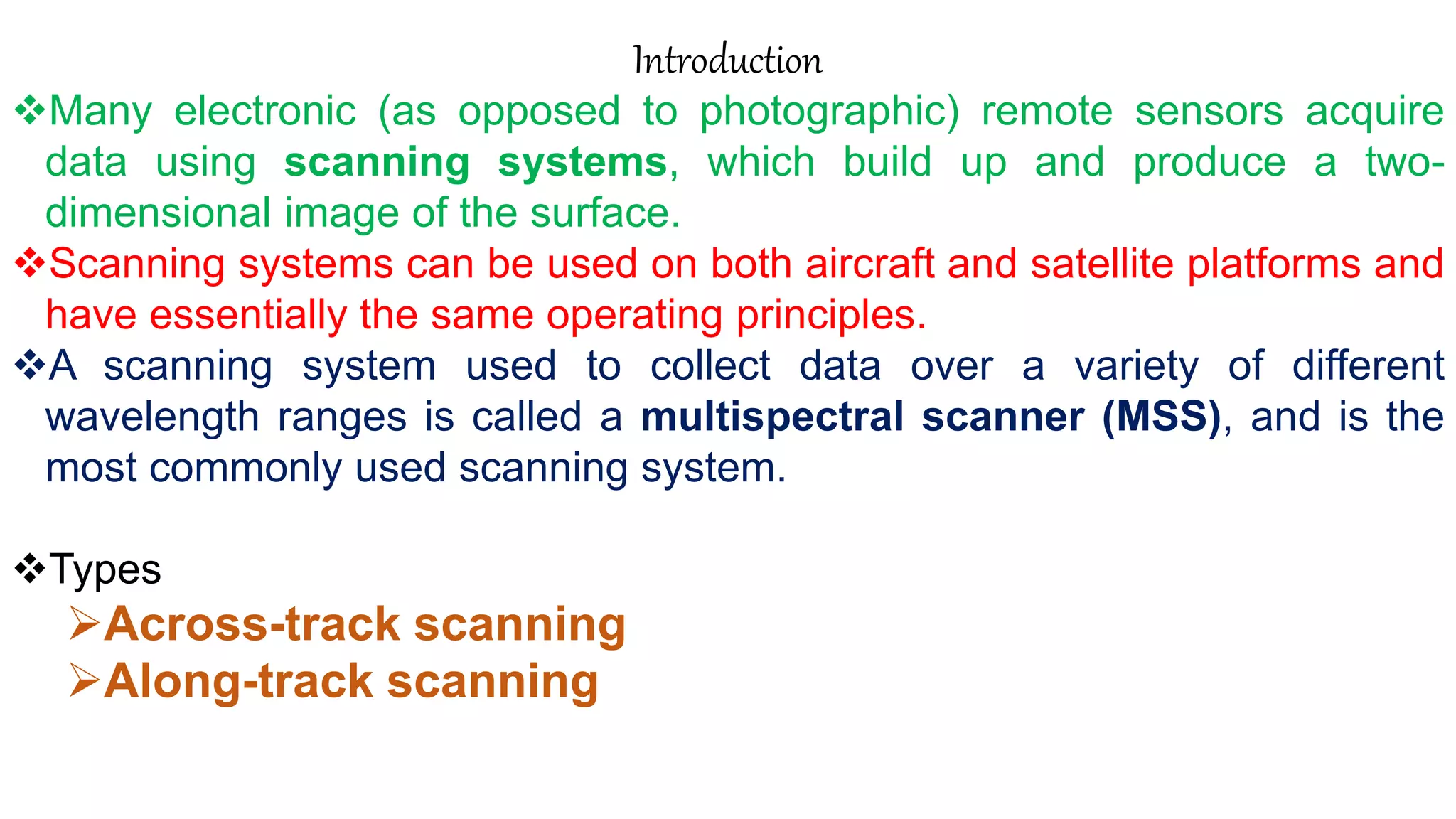
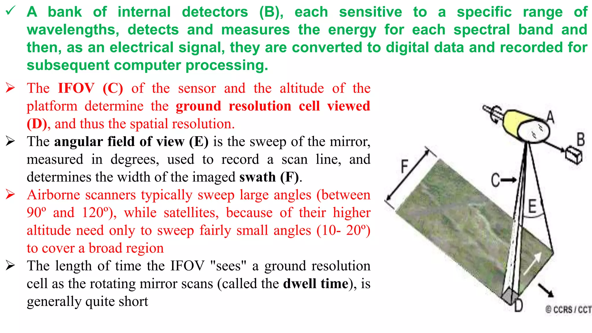
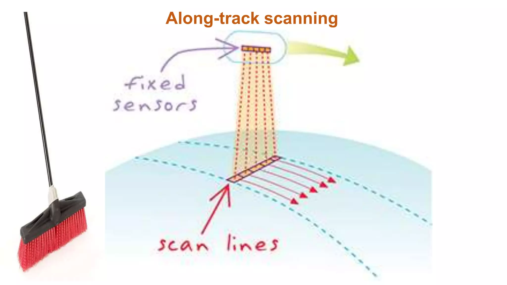
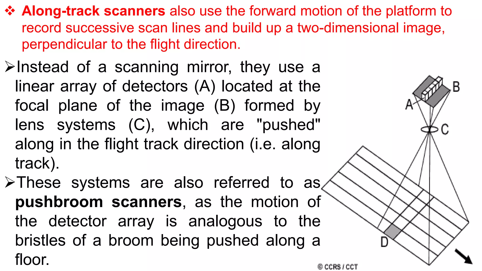
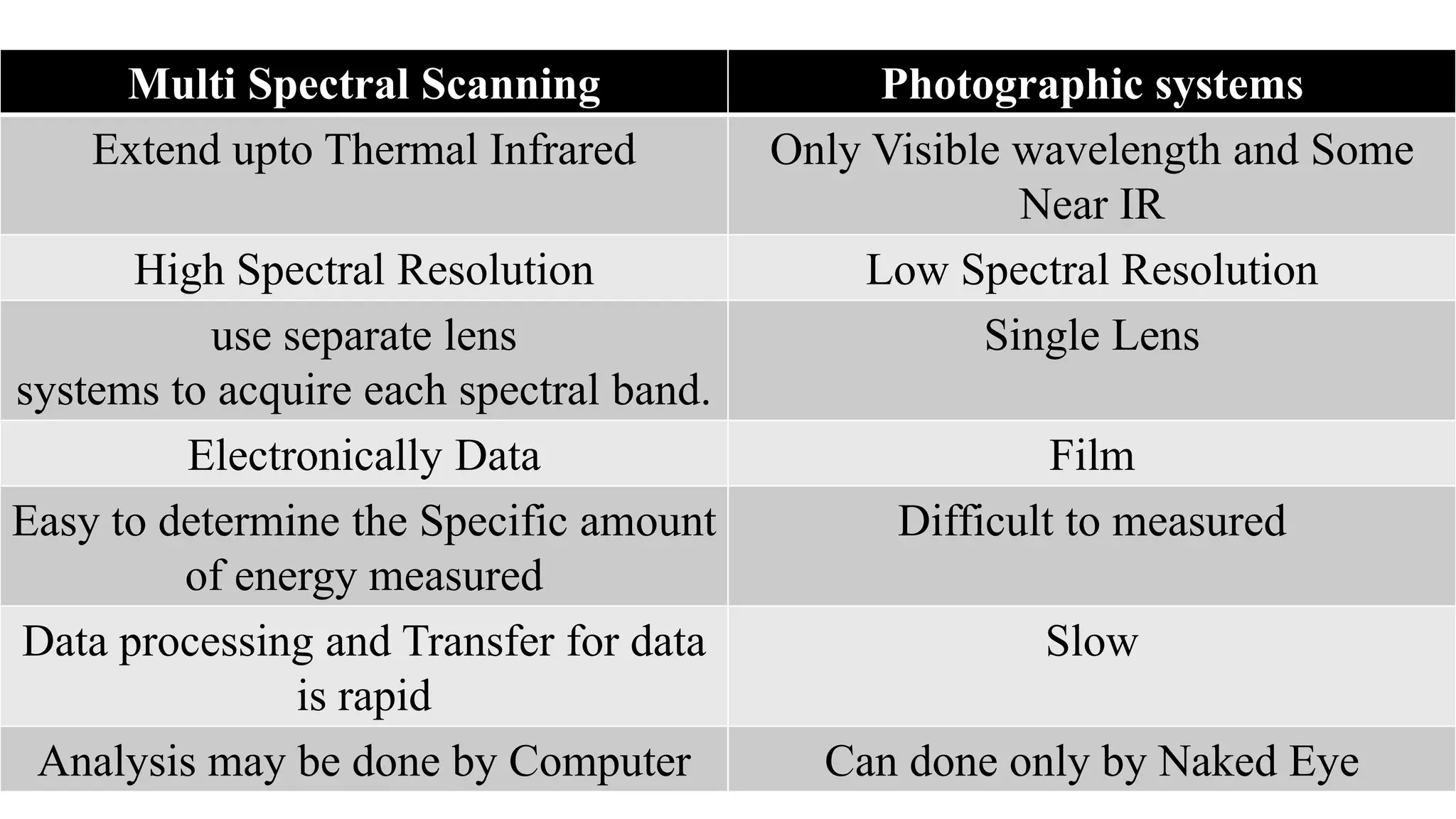
Multi Spectral scanners
M.Senthamizhan
Assistant Professor / Civil
Alagappa Chettiar Government College of
Engineering and Technology, Karaikudi
Tamilnadu
Introduction
Many electronic (as opposed to photographic) remote sensors acquire
data using scanning systems, which build up and produce a two-
dimensional image of the surface.
Scanning systems can be used on both aircraft and satellite platforms and
have essentially the same operating principles.
A scanning system used to collect data over a variety of different
wavelength ranges is called a multispectral scanner (MSS), and is the
most commonly used scanning system.
Types
Across-track scanning
Along-track scanning
Across-track scanning
 Across-track scanners scan the Earth in a series of lines. The lines
are oriented perpendicular to the direction of motion of the sensor
platform (i.e. across the swath).
Each line is scanned from one side of the sensor
to the other, using a rotating mirror (A).
As the platform moves forward over the Earth,
successive scans build up a two-dimensional
image of the Earth´s surface.
The incoming reflected or emitted radiation is
separated into several spectral components that
are detected independently. The UV, visible,
near-infrared, and thermal radiation are
dispersed into their constituent wavelengths.
 A bank of internal detectors (B), each sensitive to a specific range of
wavelengths, detects and measures the energy for each spectral band and
then, as an electrical signal, they are converted to digital data and recorded for
subsequent computer processing.
 The IFOV (C) of the sensor and the altitude of the
platform determine the ground resolution cell viewed
(D), and thus the spatial resolution.
 The angular field of view (E) is the sweep of the mirror,
measured in degrees, used to record a scan line, and
determines the width of the imaged swath (F).
 Airborne scanners typically sweep large angles (between
90º and 120º), while satellites, because of their higher
altitude need only to sweep fairly small angles (10- 20º)
to cover a broad region
 The length of time the IFOV "sees" a ground resolution
cell as the rotating mirror scans (called the dwell time), is
generally quite short
Along-track scanning
 Along-track scanners also use the forward motion of the platform to
record successive scan lines and build up a two-dimensional image,
perpendicular to the flight direction.
Instead of a scanning mirror, they use a
linear array of detectors (A) located at the
focal plane of the image (B) formed by
lens systems (C), which are "pushed"
along in the flight track direction (i.e. along
track).
These systems are also referred to as
pushbroom scanners, as the motion of
the detector array is analogous to the
bristles of a broom being pushed along a
floor.
Each individual detector measures the
energy for a single ground resolution cell
(D) and thus the size and IFOV of the
detectors determines the spatial resolution
of the system.
A separate linear array is required to
measure each spectral band or channel.
For each scan line, the energy detected
by each detector of each linear array is
sampled electronically and digitally
recorded.
Multi Spectral Scanning Photographic systems
Extend upto Thermal Infrared Only Visible wavelength and Some
Near IR
High Spectral Resolution Low Spectral Resolution
use separate lens
systems to acquire each spectral band.
Single Lens
Electronically Data Film
Easy to determine the Specific amount
of energy measured
Difficult to measured
Data processing and Transfer for data
is rapid
Slow
Analysis may be done by Computer Can done only by Naked Eye

Multi Spectral Scanning Systems

  • 1.
    Multi Spectral scanners M.Senthamizhan AssistantProfessor / Civil Alagappa Chettiar Government College of Engineering and Technology, Karaikudi Tamilnadu
  • 2.
    Introduction Many electronic (asopposed to photographic) remote sensors acquire data using scanning systems, which build up and produce a two- dimensional image of the surface. Scanning systems can be used on both aircraft and satellite platforms and have essentially the same operating principles. A scanning system used to collect data over a variety of different wavelength ranges is called a multispectral scanner (MSS), and is the most commonly used scanning system. Types Across-track scanning Along-track scanning
  • 3.
  • 4.
     Across-track scannersscan the Earth in a series of lines. The lines are oriented perpendicular to the direction of motion of the sensor platform (i.e. across the swath). Each line is scanned from one side of the sensor to the other, using a rotating mirror (A). As the platform moves forward over the Earth, successive scans build up a two-dimensional image of the Earth´s surface. The incoming reflected or emitted radiation is separated into several spectral components that are detected independently. The UV, visible, near-infrared, and thermal radiation are dispersed into their constituent wavelengths.
  • 5.
     A bankof internal detectors (B), each sensitive to a specific range of wavelengths, detects and measures the energy for each spectral band and then, as an electrical signal, they are converted to digital data and recorded for subsequent computer processing.  The IFOV (C) of the sensor and the altitude of the platform determine the ground resolution cell viewed (D), and thus the spatial resolution.  The angular field of view (E) is the sweep of the mirror, measured in degrees, used to record a scan line, and determines the width of the imaged swath (F).  Airborne scanners typically sweep large angles (between 90º and 120º), while satellites, because of their higher altitude need only to sweep fairly small angles (10- 20º) to cover a broad region  The length of time the IFOV "sees" a ground resolution cell as the rotating mirror scans (called the dwell time), is generally quite short
  • 6.
  • 7.
     Along-track scannersalso use the forward motion of the platform to record successive scan lines and build up a two-dimensional image, perpendicular to the flight direction. Instead of a scanning mirror, they use a linear array of detectors (A) located at the focal plane of the image (B) formed by lens systems (C), which are "pushed" along in the flight track direction (i.e. along track). These systems are also referred to as pushbroom scanners, as the motion of the detector array is analogous to the bristles of a broom being pushed along a floor.
  • 8.
    Each individual detectormeasures the energy for a single ground resolution cell (D) and thus the size and IFOV of the detectors determines the spatial resolution of the system. A separate linear array is required to measure each spectral band or channel. For each scan line, the energy detected by each detector of each linear array is sampled electronically and digitally recorded.
  • 9.
    Multi Spectral ScanningPhotographic systems Extend upto Thermal Infrared Only Visible wavelength and Some Near IR High Spectral Resolution Low Spectral Resolution use separate lens systems to acquire each spectral band. Single Lens Electronically Data Film Easy to determine the Specific amount of energy measured Difficult to measured Data processing and Transfer for data is rapid Slow Analysis may be done by Computer Can done only by Naked Eye