Downloaded 620 times


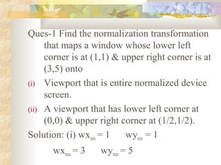
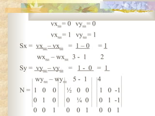
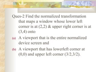

Here are the steps to solve this question: (a) Given: Window: wxmin = 2, wymin = 2 wxmax = 3, wymax = 4 Viewport: vxmin = 0, vymin = 0 vxmax = 1, vymax = 1 Sx = 1 - 0 = 1/1 = 1 3 - 2 = 1 Sy = 1 - 0 = 1/2 = 1/2 4 - 2 = 2 N = 1 0 0 0 1 0 0 0 1 (b) Given: Window: wxmin = 2, wymin = 2 wxmax = 3, wymax = 4 Viewport


![MODULE-5 notes [BCG402-CG&V] PART-B.pdf](https://cdn.slidesharecdn.com/ss_thumbnails/module-5notesbcg402-cgvpart-b-250630054728-c1eaacea-thumbnail.jpg?width=640&height=640&fit=bounds)