This document discusses windowing and clipping in computer graphics. It introduces key concepts such as:
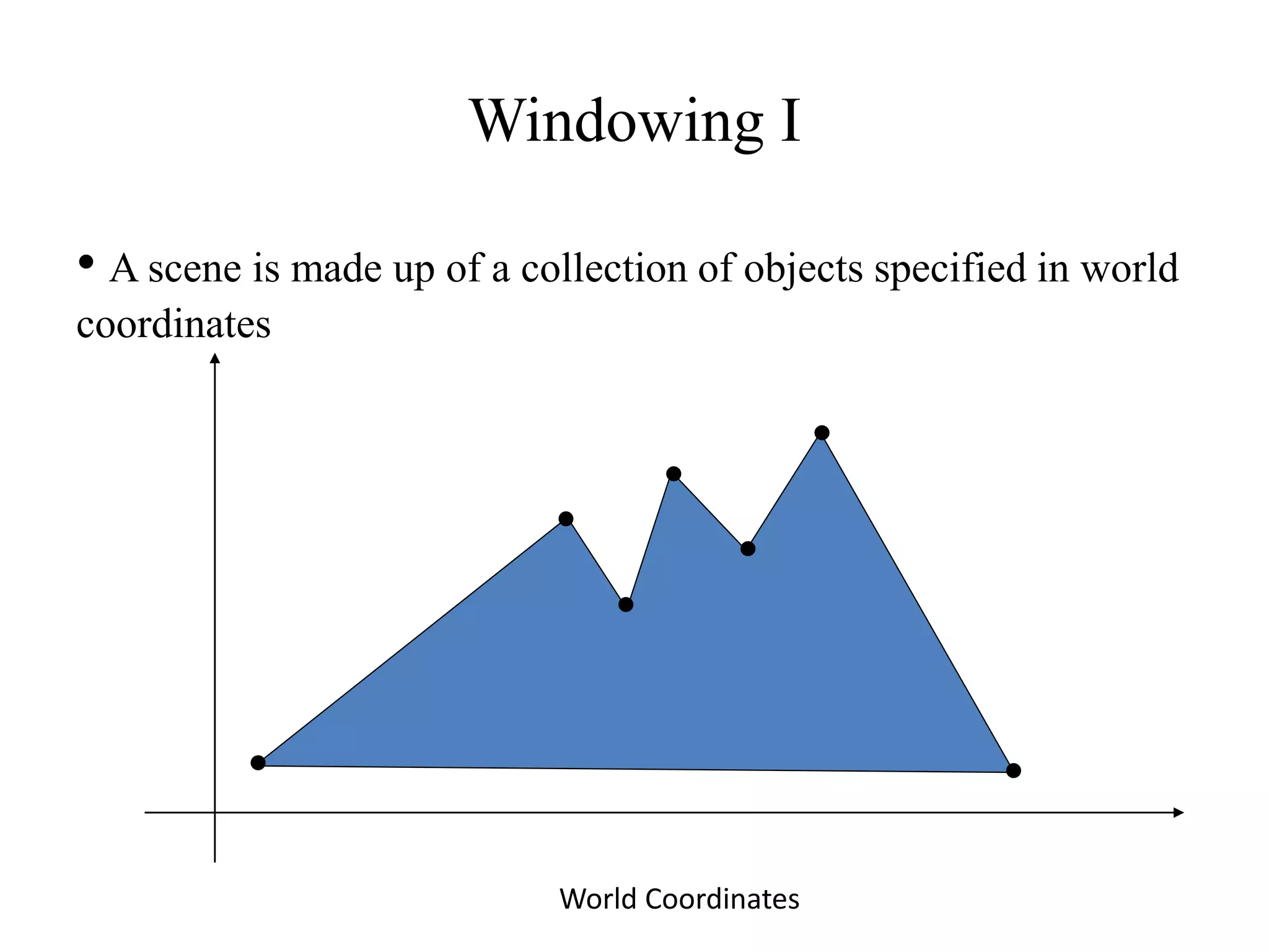
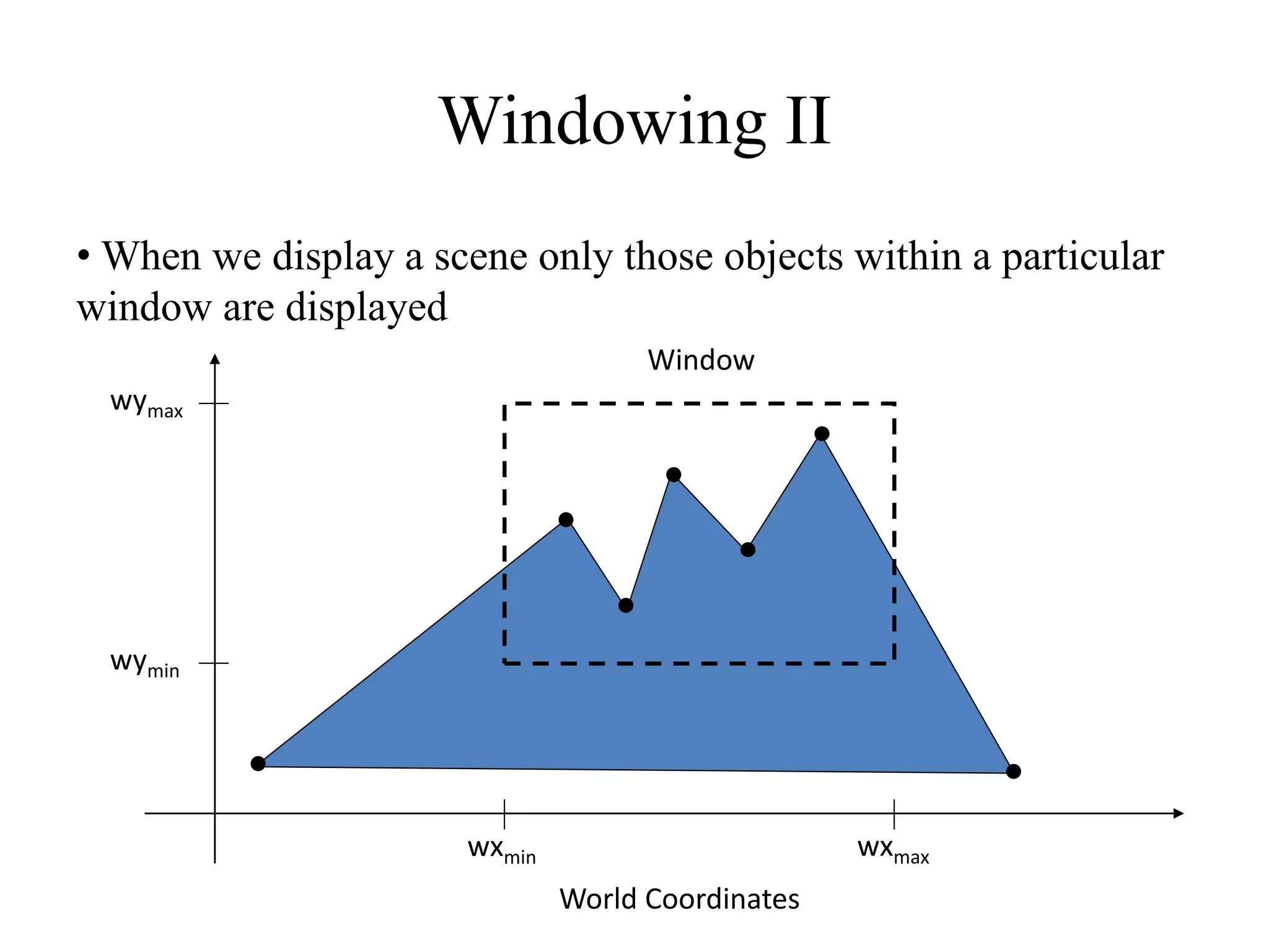
- A scene is defined using world coordinates, but only objects within the clipping window are displayed.
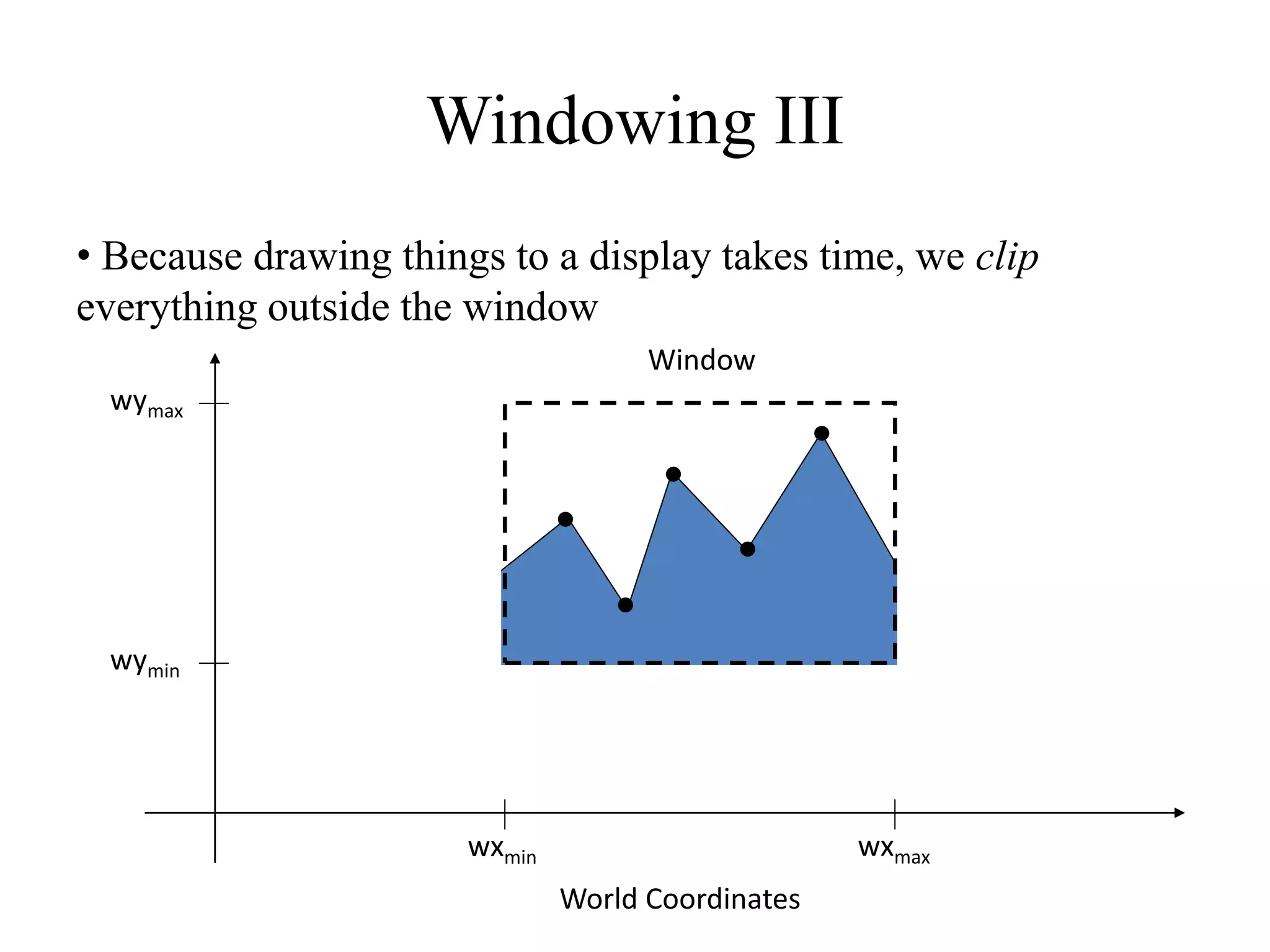
- Clipping removes objects outside the window to optimize rendering time.
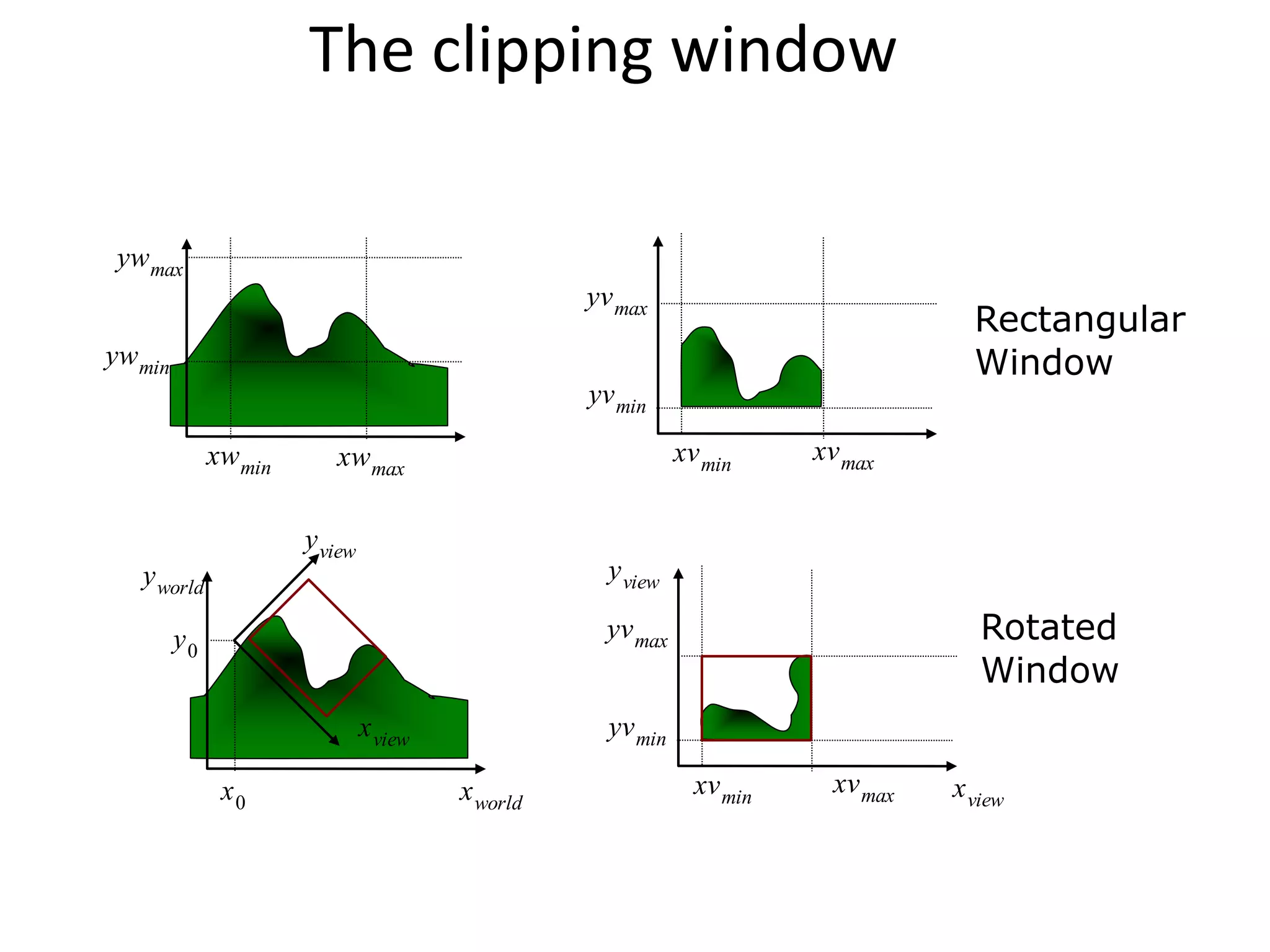
- Graphics packages commonly use a rectangular clipping window aligned to axes for simplicity.
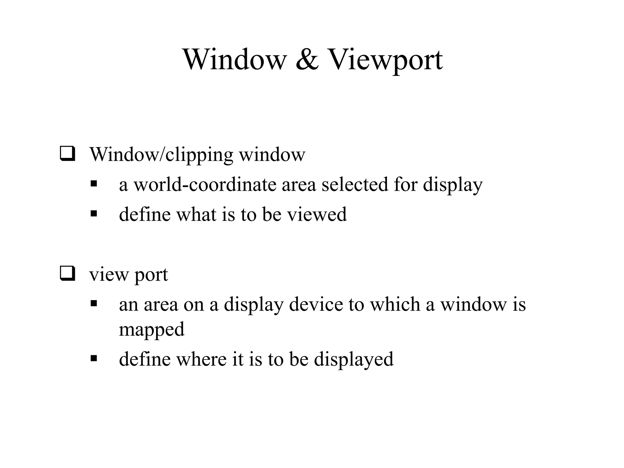
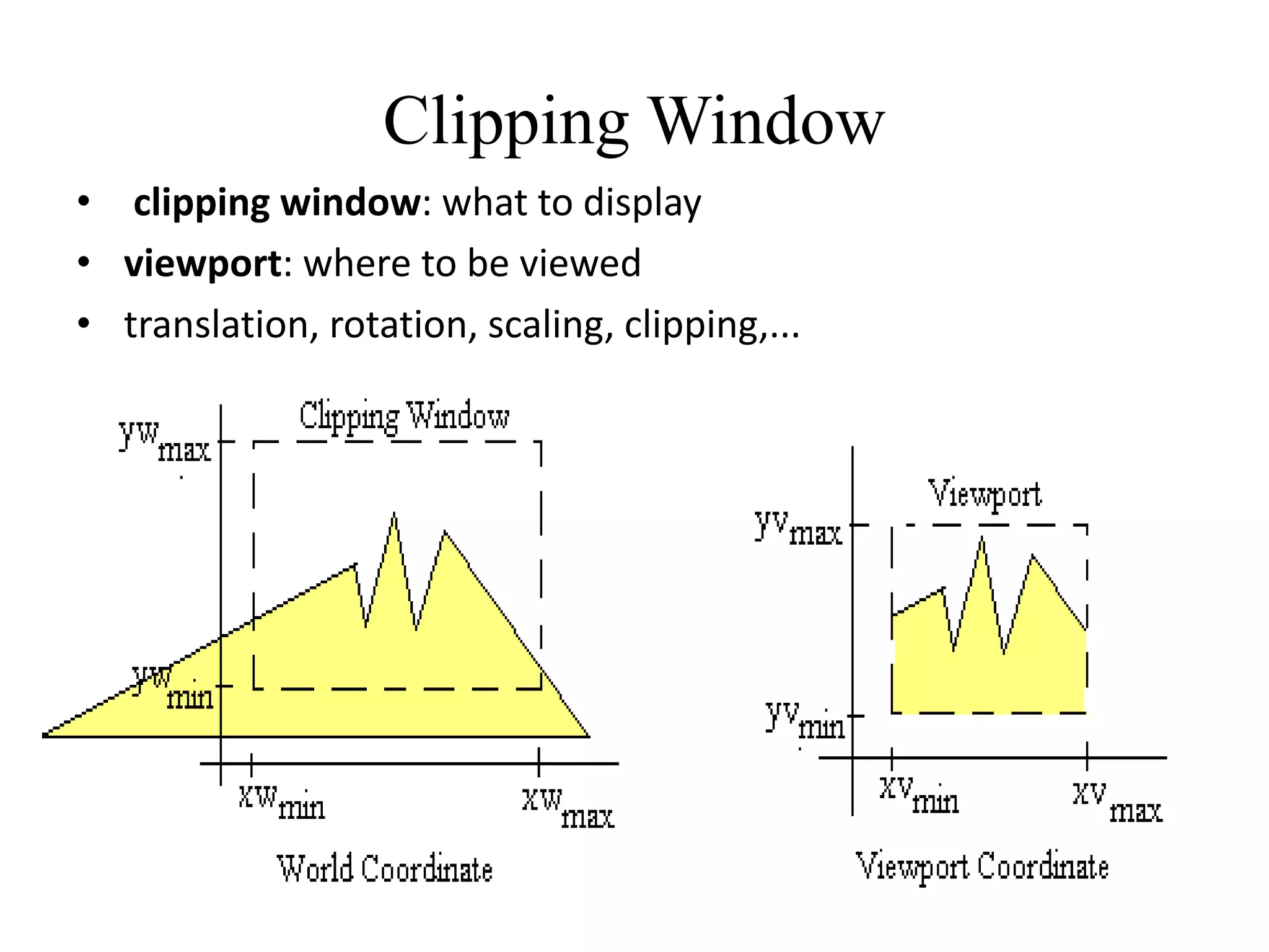
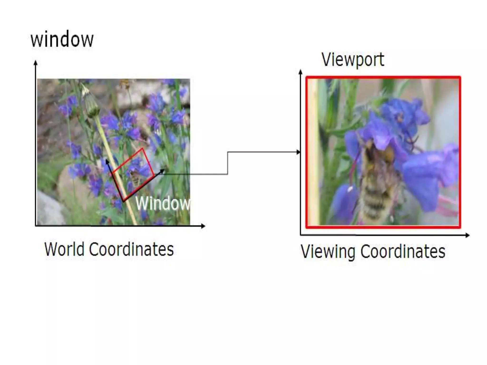
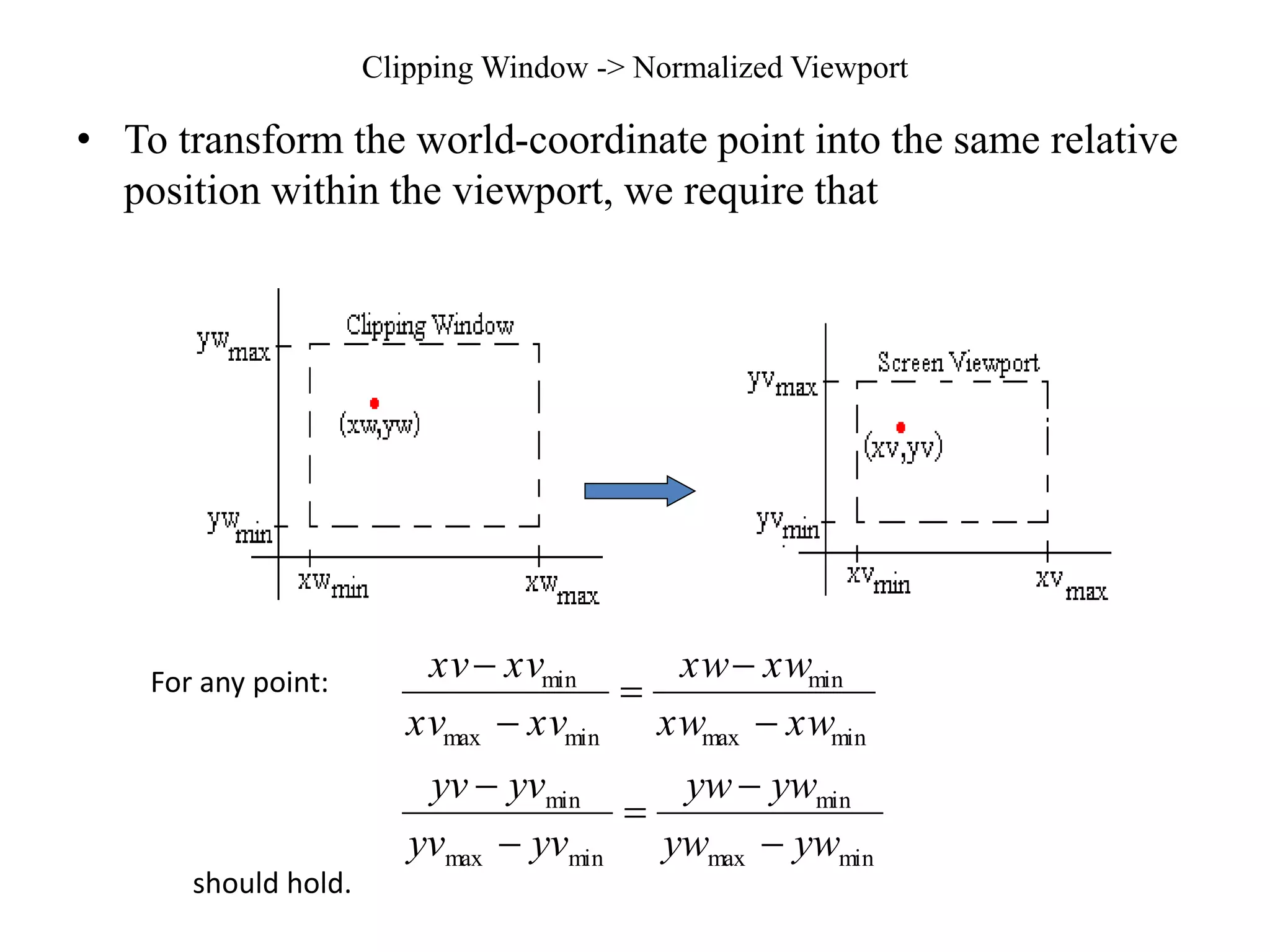
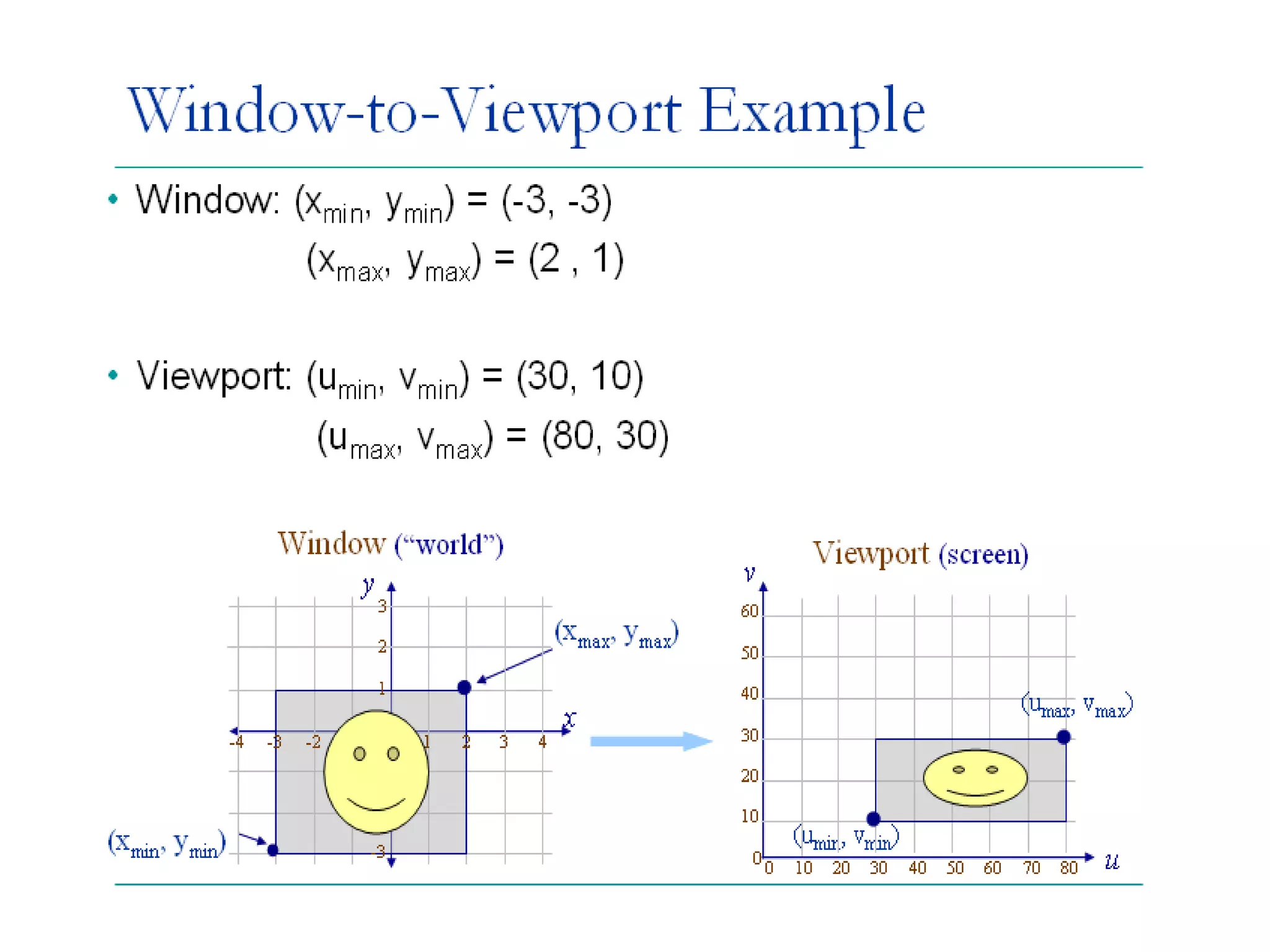
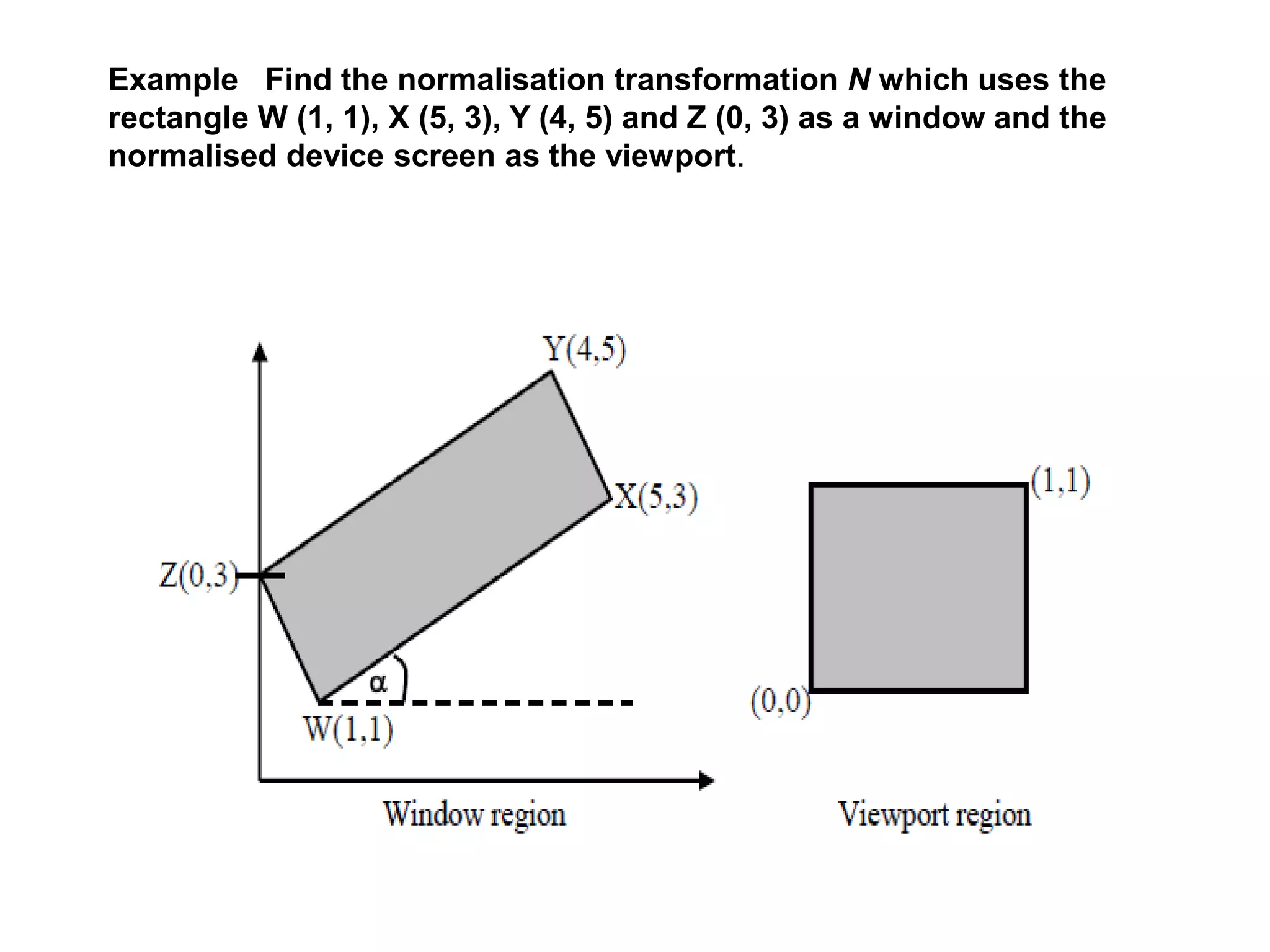
- The clipping window defines what parts of the scene to display, while the viewport defines where on screen.
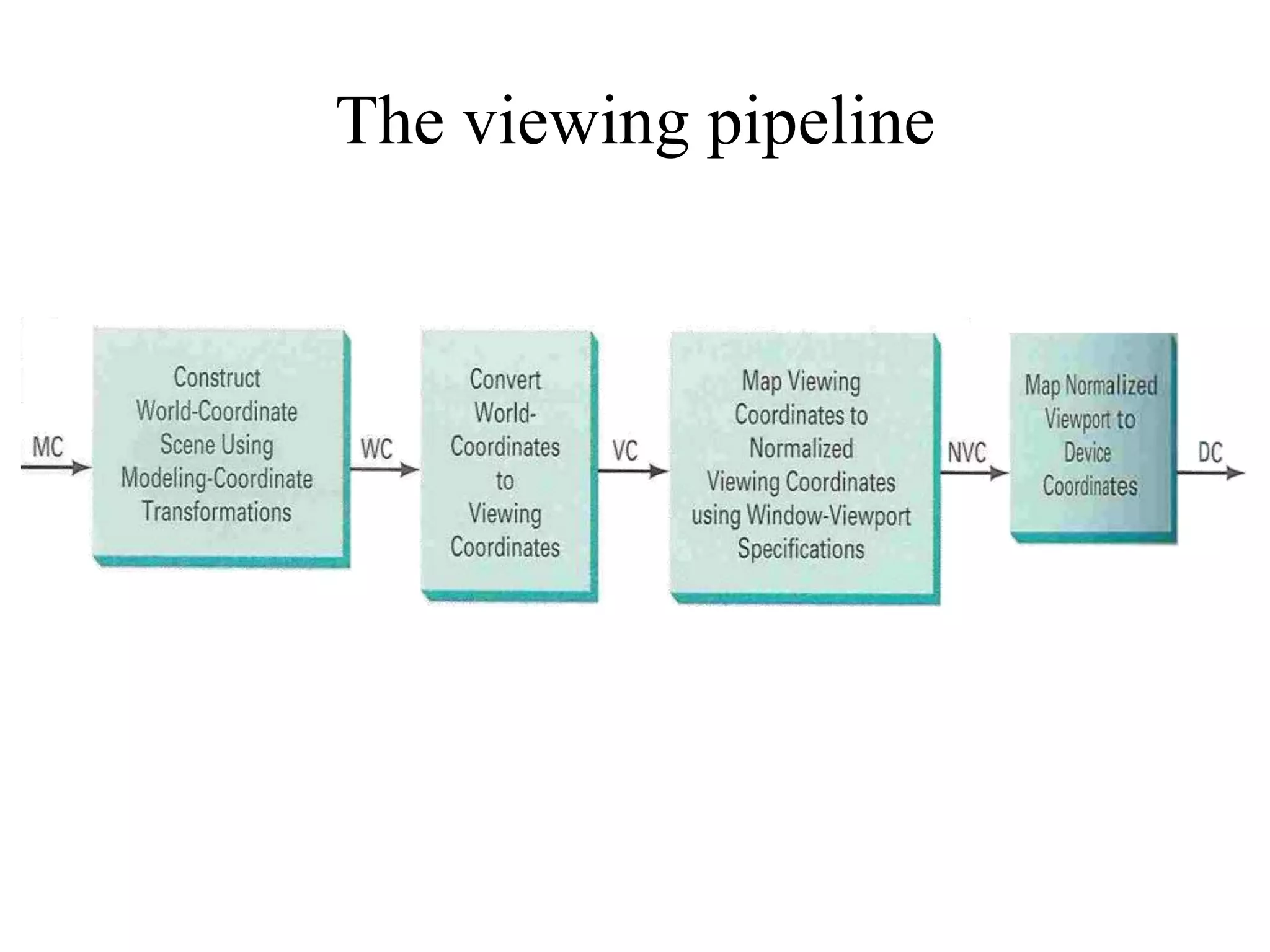
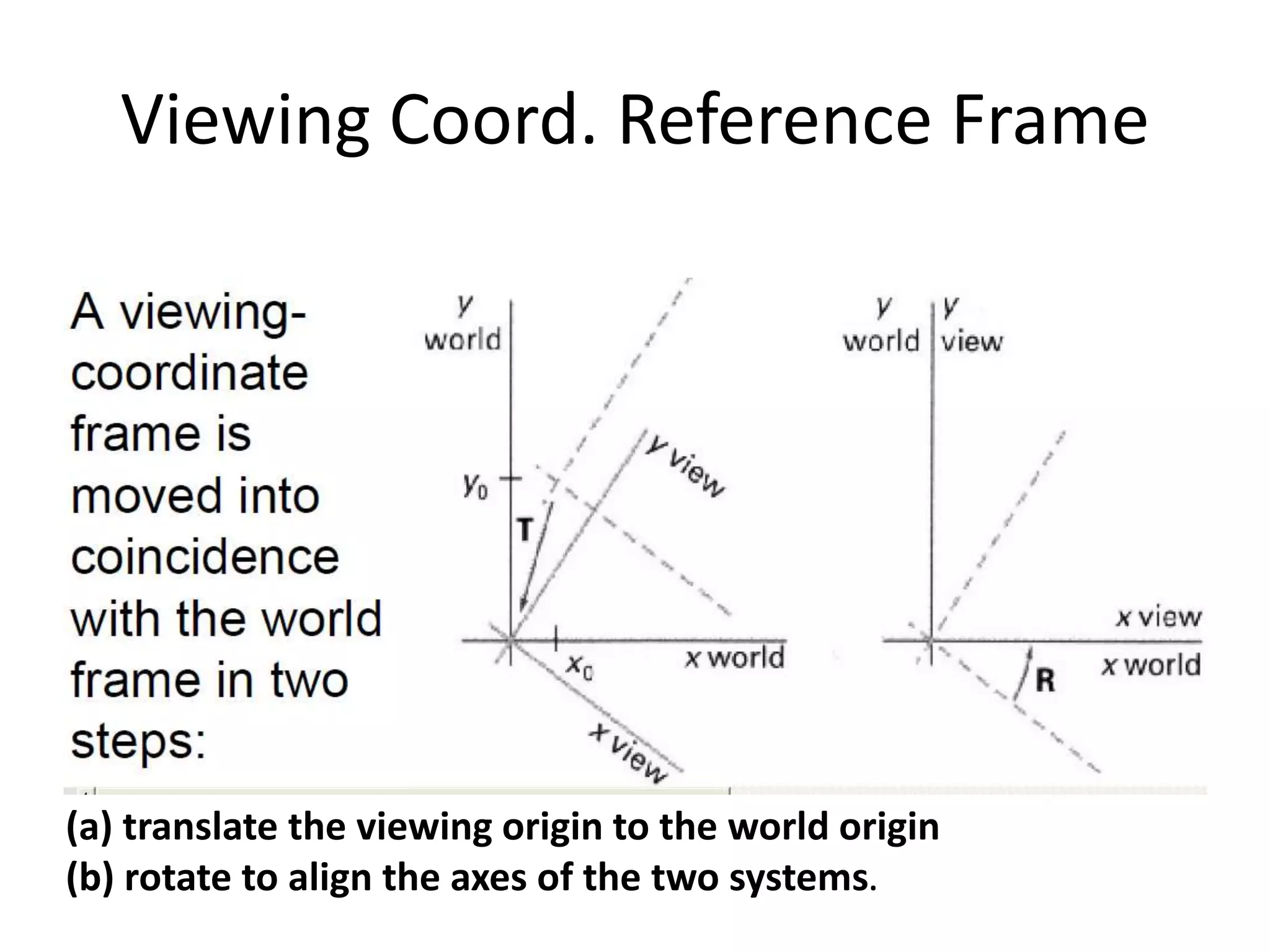
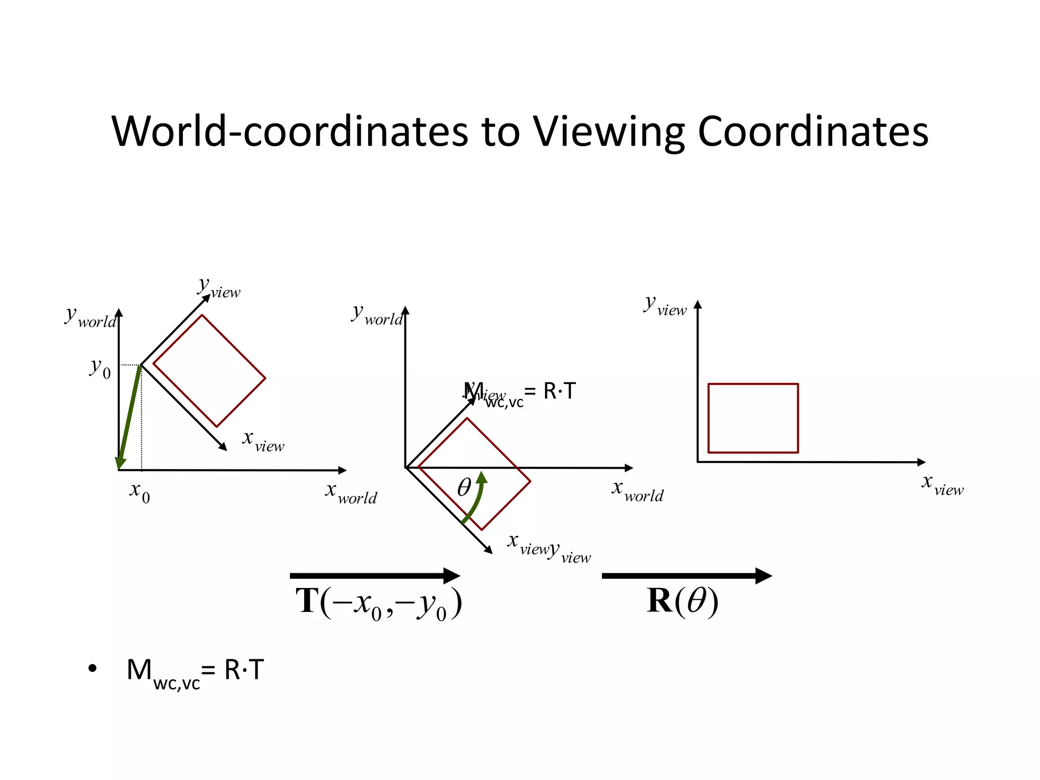
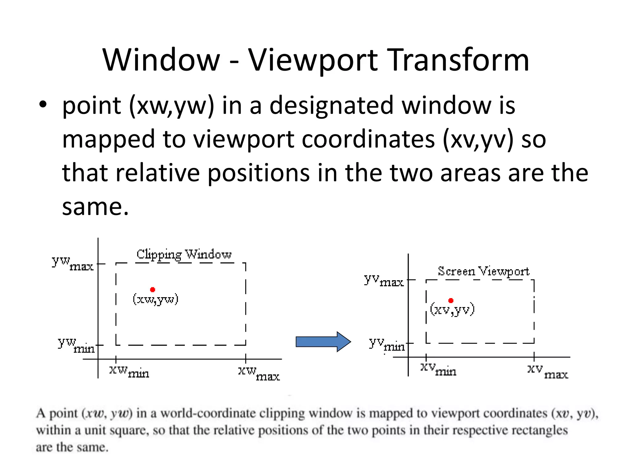
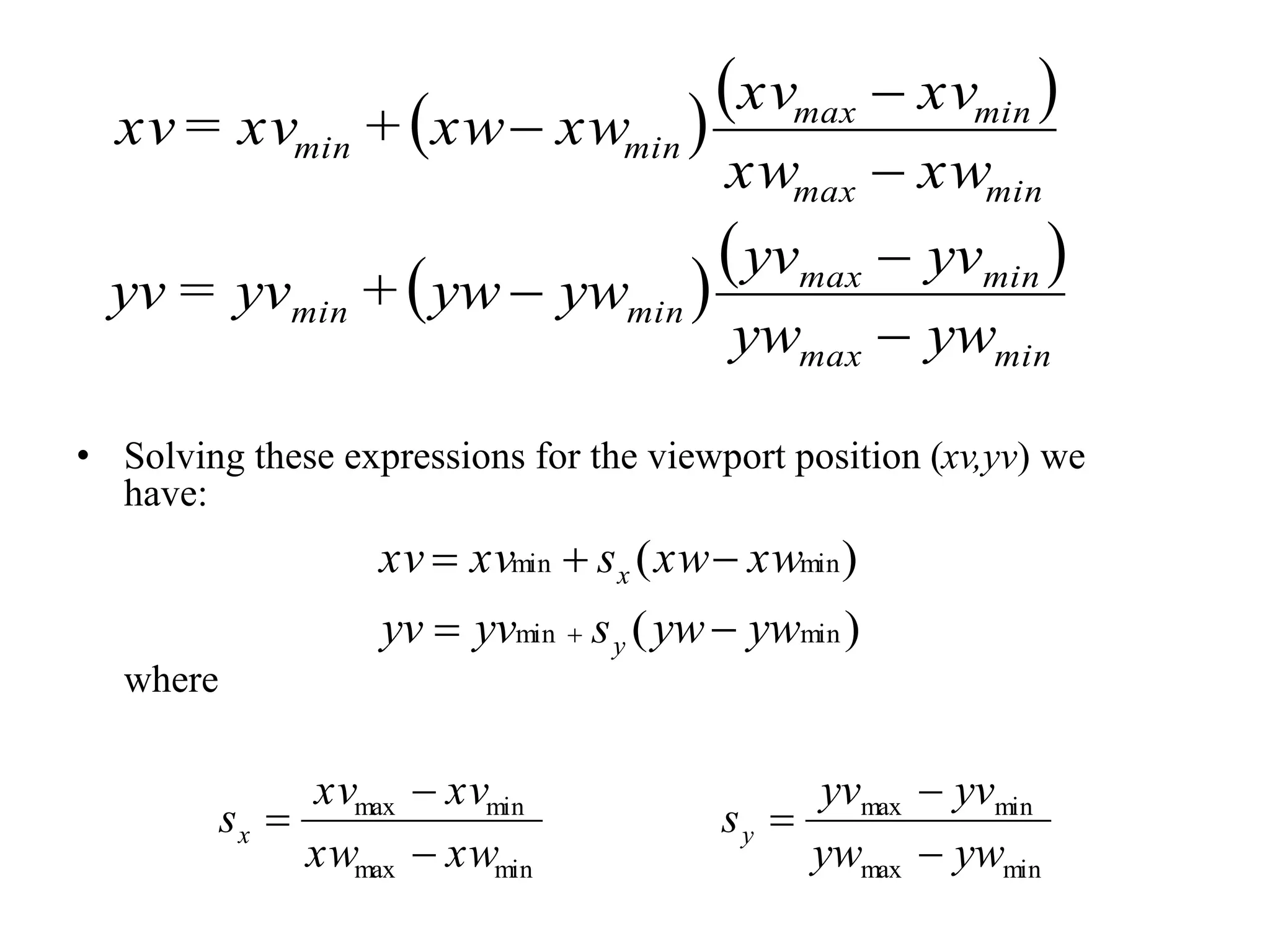
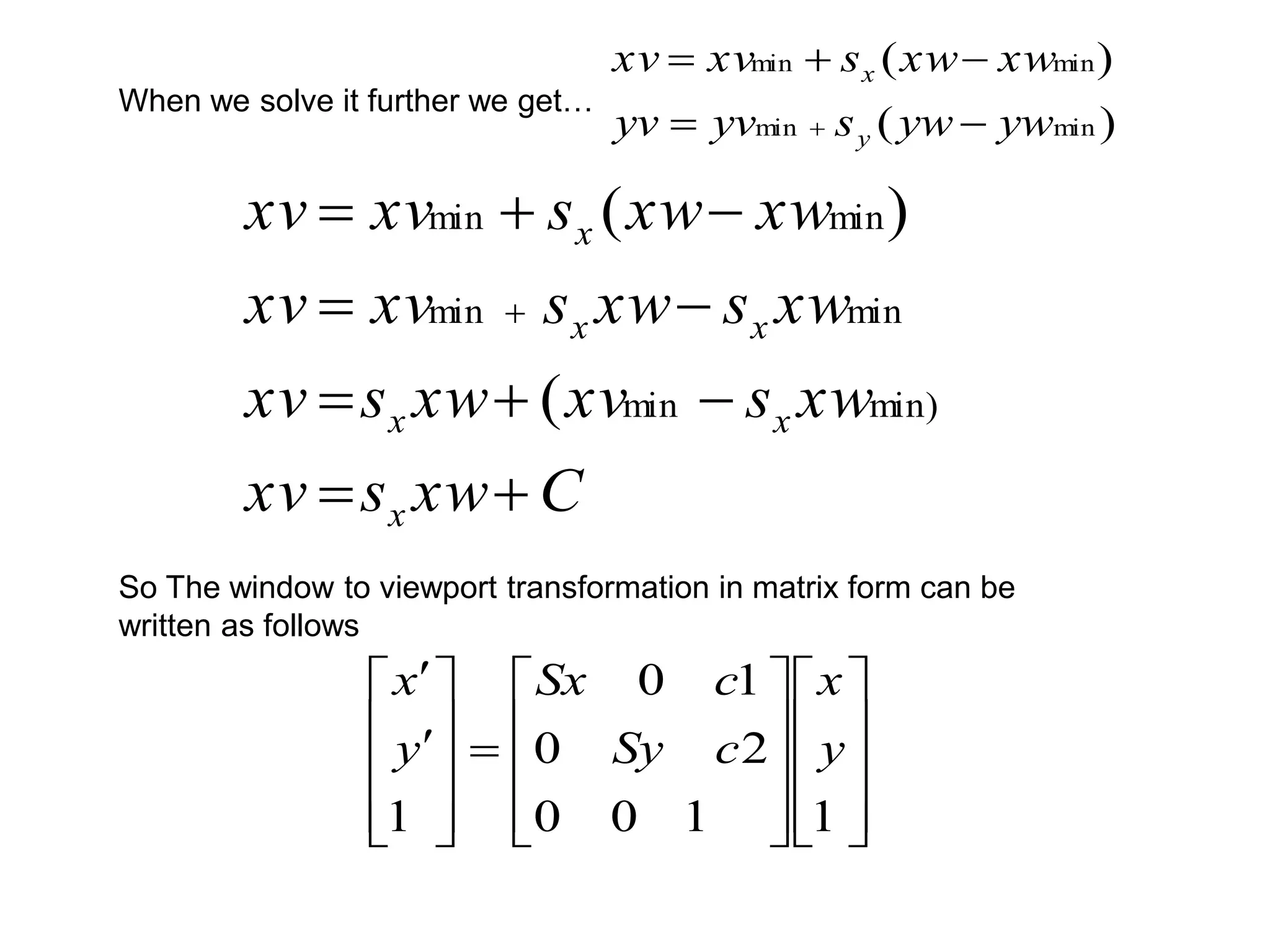
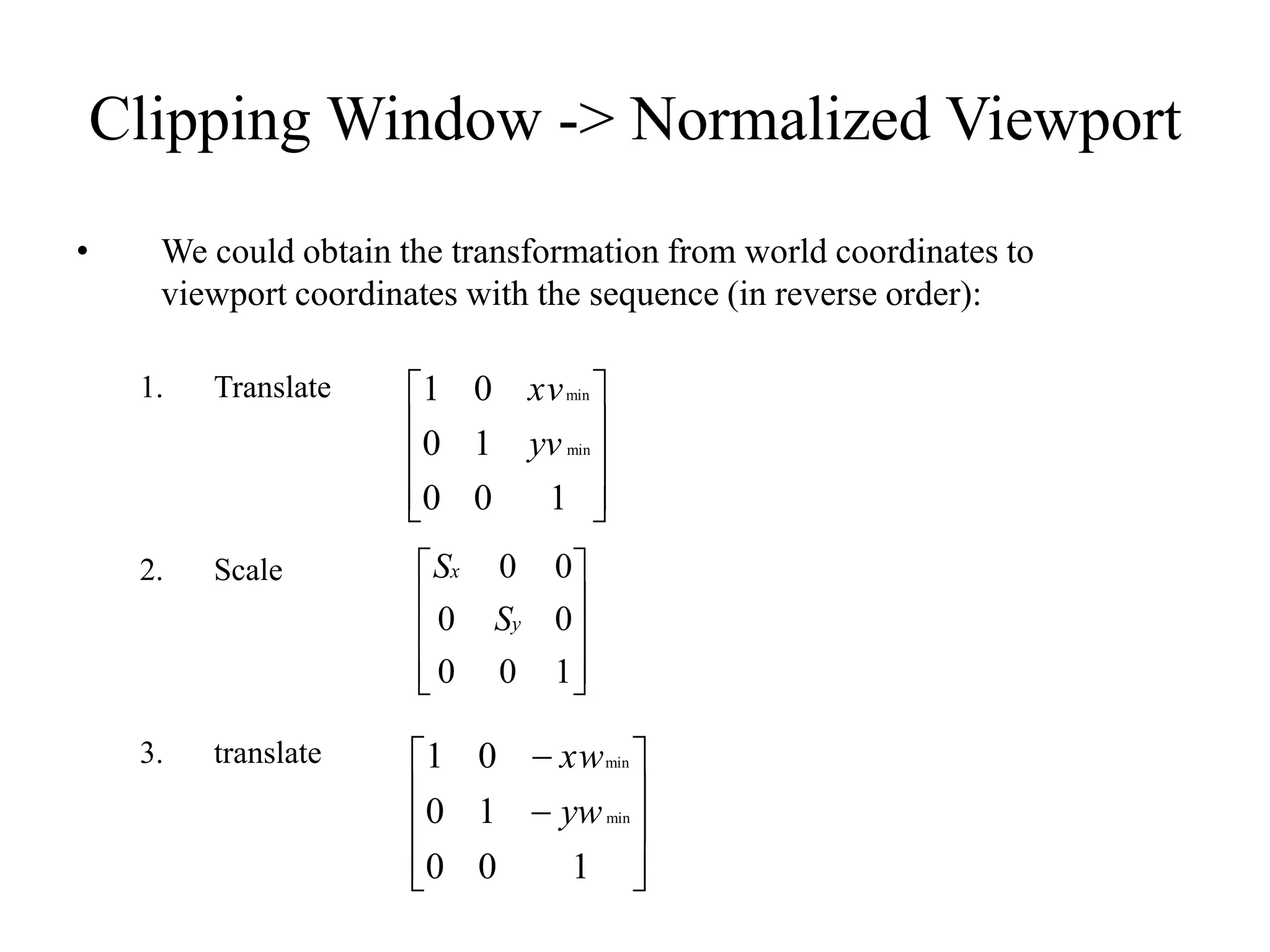
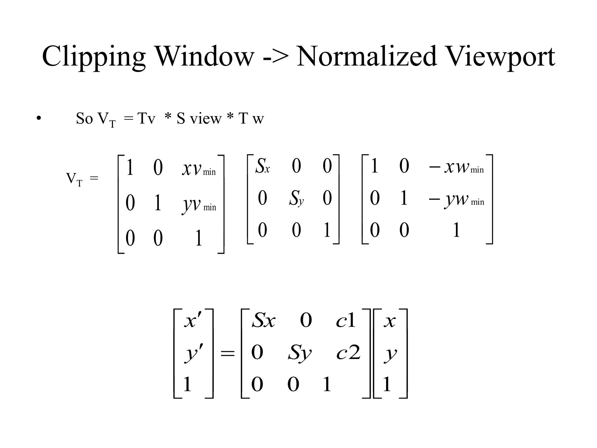
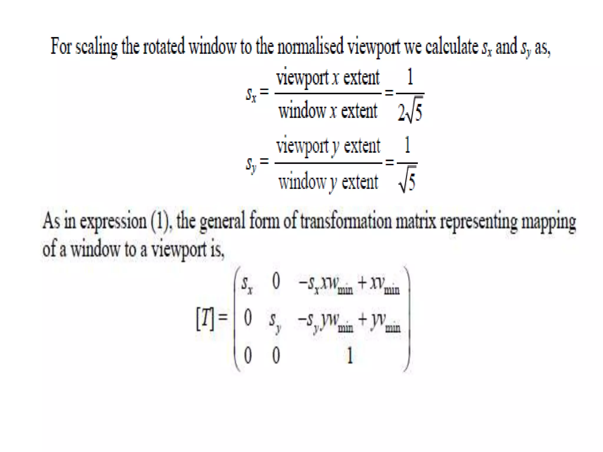
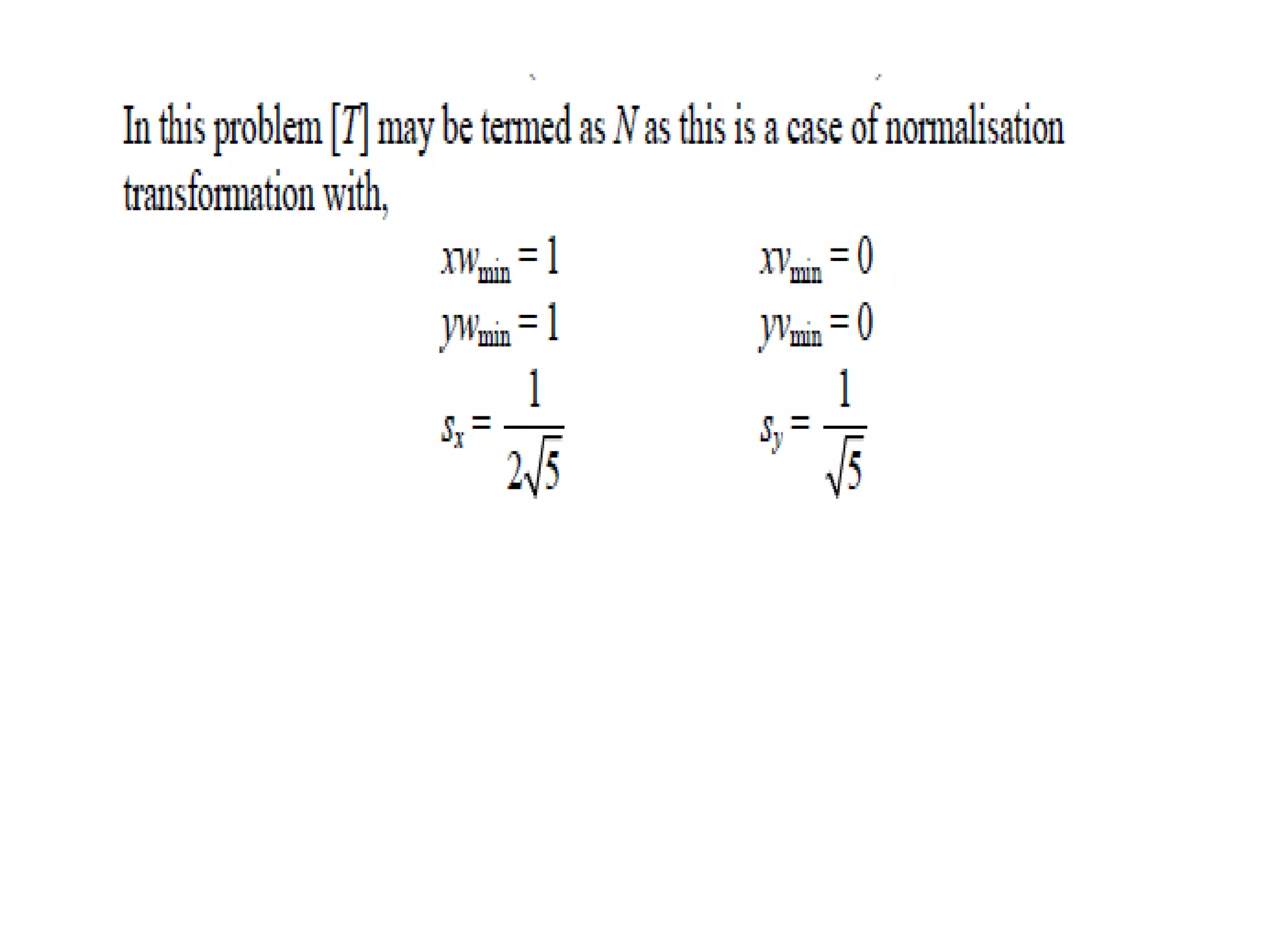
- Transformations are used to map points from the clipping window to the normalized viewport.
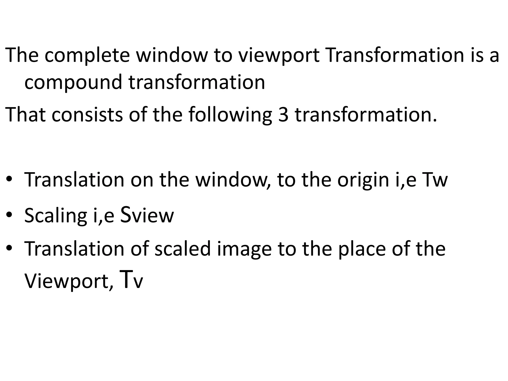
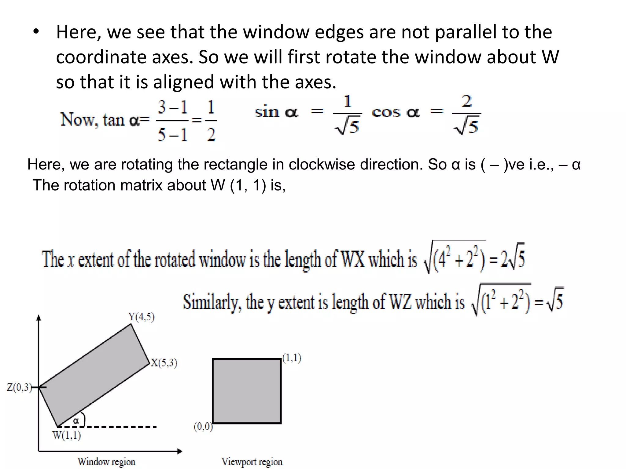
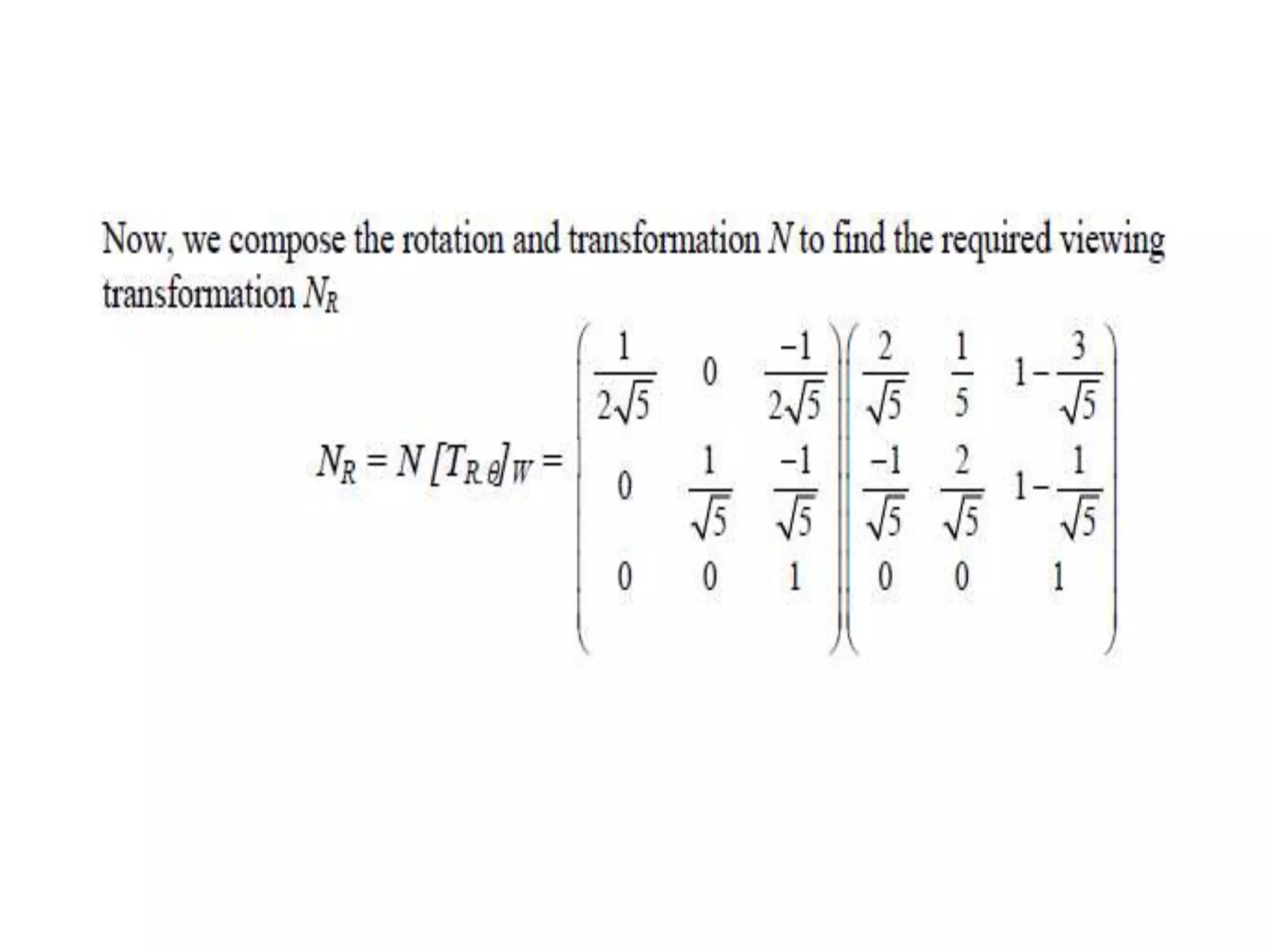
The full transformation involves translating to the window origin, scaling to the viewport, and translating to the final viewport position. Rectangular clipping windows aligned to