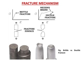
- Fracture is the separation of an object into pieces due to stress. There are two main types: ductile fracture and brittle fracture.
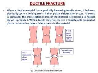
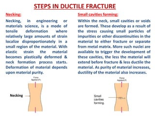
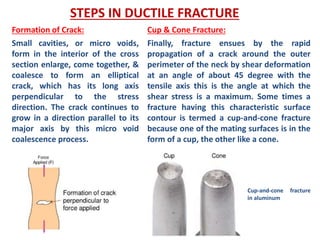
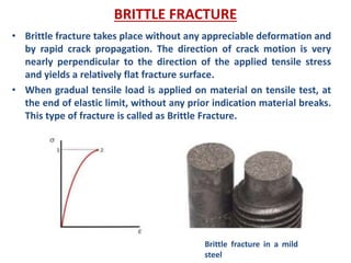
- Ductile fracture involves plastic deformation and occurs through processes like necking and the formation and coalescence of microvoids. It results in a cup-and-cone pattern. Brittle fracture occurs suddenly without plastic deformation.
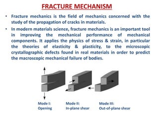
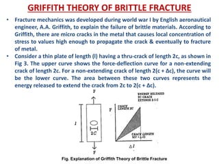
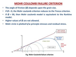
- Fracture mechanics studies how cracks propagate in materials. The Griffith theory and models like the Mohr-Coulomb criterion describe how stresses lead to fracture based on factors like crack size and material properties.