Downloaded 120 times


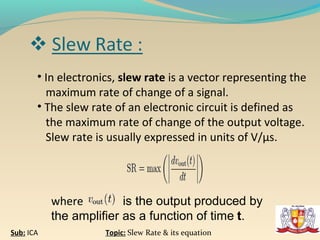
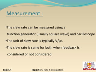


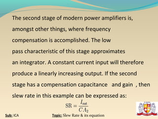


This document discusses slew rate and its equation in operational amplifiers. It defines slew rate as the maximum rate of change of the output voltage of a circuit. The slew rate equation is provided as the derivative of the output voltage with respect to time. It also explains that slew rate limits the maximum input frequency and amplitude that can be applied to an amplifier without distorting the output. The document provides background on operational amplifiers and describes how their internal stages contribute to slew rate.