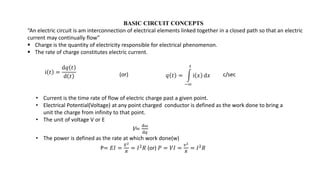
A circuit consists of electrical elements connected in a closed loop to allow current flow. Key concepts include:
- Current is the flow of electric charge. Voltage is electrical potential difference and power is the rate of work done.
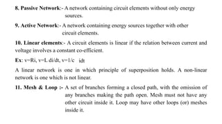
- Circuits have active elements like voltage and current sources that supply energy and passive elements like resistors, inductors and capacitors that receive energy.
- Kirchhoff's laws state that the algebraic sum of voltages around any loop is zero and the algebraic sum of currents at any node is zero.
- Resistors in series add, resistors in parallel calculate using reciprocal formula. Source transformations allow representing one source type as another while maintaining terminal characteristics.
![Energy is the capacity to do work (kwh or unit)
W= 𝐸𝐼𝑇 =
𝐸2𝑡
𝑅
= 𝐼2𝑅
Elements of electric circuits:
Electric circuit consists of two types of elements
1.Active elements or Sources
2.Passive elements or Sinks.
1.Active elements: They are the elements of the circuits which posses energy of their own and can impact it to
other elements on the circuits”[Independent sources]
They are two types of Active elements
1.Voltage Source
2.Current Source
“An ideal voltage source is one ,which delivers energy to a load at constant terminal voltage
irrespective of the current drawn from the load.”
“An ideal Current source is the one ,which delivers energy with a constant current to the load,
irrespective of the terminal voltage at the load.”](https://image.slidesharecdn.com/upto3180s1-221211101823-fe087e94/85/Network-Analysis-2-320.jpg)


![I = I1 + I2
I = I1 + V/R2
I = I1 + IR/R2
I1 = I[1-R/R2]
I1 = I[1-R/R2]
I1 = I[1-(R1R2/R1+R2)/R2]
I1 = I[R1+R2-R1/R1+R2]
Similarly,
I1 = IR2/R1+R2
I2 = IR1/R1+R2](https://image.slidesharecdn.com/upto3180s1-221211101823-fe087e94/85/Network-Analysis-16-320.jpg)


![sol:
P = (V * V) / Rt = 1000
(250 * 250)/Rt = 1000
Rt = 62.5 Ω
Rt = R + [(20*48)/(20+48)]
= 62.5
R = 48.38 Ω
Source Transformation:
• Source transformation is a procedure which transforms one
source into another while retaining the terminal
characteristics of the original source.
• An equivalent circuit whose terminal characteristics remain
identical to those of the original circuit.](https://image.slidesharecdn.com/upto3180s1-221211101823-fe087e94/85/Network-Analysis-30-320.jpg)