Lec1 - Analog and Digital systems
•
2 likes•1,305 views

Introduction to Analog and Digital Systems - Basic definition, Representation, Examples and applications of Analog and Digital Systems - Advantages of Digital system over Analog system - Process of conversion from Analog to Digital and Digital to Analog signal - Digitization Examples - Signal representation of voltage and current in terms of Binary values - Representations of Binary quantities using different terminologies - IC Complexity classification - IC Layout - Development of ICs in terms of size

Recommended
More Related Content
What's hot
What's hot (20)
Similar to Lec1 - Analog and Digital systems
Similar to Lec1 - Analog and Digital systems (20)
Recently uploaded
Recently uploaded (20)
Lec1 - Analog and Digital systems
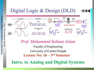
- 1. FacultyofEngineering-UCP IntroductiontoAnalogandDigitalSystems Intro. to Analog and Digital Systems Prof. Mohammad Salman Aslam Faculty of Engineering University of Central Punjab Digital Logic & Design (DLD) Lecture No: 1b – 3rd Semester
- 2. IntroductiontoAnalogandDigitalSystems FacultyofEngineering-UCP 2 Basic Definition of Analog System An Analog System or quantity is one having continuous values. A nominal continuous electrical signal that varies in amplitude or frequency in response to changes in sound, light, heat, position or pressure is called analog signal and the system based on this type of signal is called Analog System. OR An Analogue quantity is one having a continuous set of values. OR In an analog system, the quantities can vary over a continuous range of values. Most things that can be measured quantitatively appear in nature in analog form.
- 3. IntroductiontoAnalogandDigitalSystems FacultyofEngineering-UCP 3 We live in an analog world (continuous) Analog signals are continuous in nature • Smooth transition over a period of time • Represent a physical quantity or phenomenon • e.g. temperature of a cup of tea being boiled Basic Definition of Analog System (Cont.)
- 6. IntroductiontoAnalogandDigitalSystems FacultyofEngineering-UCP 6 Basic Definition of Digital System A circuit designed to respond at input voltages at one of a finite number of levels and, similarly to produce output of a finite number of levels is called digital system. And a digital quantity is one having a discrete set of values. OR A digital quantity is one having a discrete set of values. In these systems the values are not defined at every point rather on discrete points. OR A Digital quantity is one having a discrete set of values. A Digital quantity is often a sampled analogue quantity. Examples of Digital Systems are Digital Computers; Digital Telephone switching exchanges, Digital voltmeter, Frequency counter, Calculators etc.
- 7. IntroductiontoAnalogandDigitalSystems FacultyofEngineering-UCP 7 Representation of Digital System
- 8. IntroductiontoAnalogandDigitalSystems FacultyofEngineering-UCP 8 Representation of Digital System
- 9. IntroductiontoAnalogandDigitalSystems FacultyofEngineering-UCP 9 Advantages of Digital System An increasing majority of applications in electronics as well as in most other technologies use digital techniques to perform operations that were once preformed using analog methods. The main reasons to use the digital technology are: Digital system is generally easier to design. Information storage is easier in Digital Systems. Accuracy and precision are greater. Operation can be easily programmed. Digital circuits are less affected by noise.
- 10. IntroductiontoAnalogandDigitalSystems FacultyofEngineering-UCP 10 Disadvantage of Digital System There is really only one major drawback when using Digital System techniques: The real world is mainly Analog. Most physical quantities are Analog in nature, and it is these quantities that are often the inputs and outputs that are being monitored, operated on, and controlled by a system.
- 11. IntroductiontoAnalogandDigitalSystems FacultyofEngineering-UCP 11 Process of Conversion from a Analog-to-Digital (ADC) and Digital to Analog (DAC) Signal To take advantage of digital techniques when dealing with analog inputs and outputs, three steps must be followed: 1. Convert the real-world analog inputs to digital form. (ADC) 2. Process (operate on) the digital information. 3. Convert the digital outputs back to real-world analog form. (DAC) The following diagram shows a temperature control system that requires analog/digital conversions in order to allow the use of digital processing techniques.
- 12. IntroductiontoAnalogandDigitalSystems FacultyofEngineering-UCP 12 Process of Conversion from a Analog-to-Digital (ADC) and Digital to Analog (DAC) Signal Digitization (Why?) Process of conversion from analog to digital is called digitization Analog to digital (ADC) converters perform digitization Digital to analog (DAC) converters regenerate the analog signals from their digitized form The world around us is analog Digital systems are simple to understand & comprehend Thus common practice is to convert analog signals into digital signals form for efficient processing of signals Inevitable to avoid loss of some accuracy (information) due to this conversion Reason: digital systems can only represent fixed (finite or discrete) set of values
- 13. IntroductiontoAnalogandDigitalSystems FacultyofEngineering-UCP 13 Digitization Example (Converting Analog signal into Digital)
- 14. IntroductiontoAnalogandDigitalSystems FacultyofEngineering-UCP 14 Signal representation (Voltage) Computers use low power supply voltage, typically from 0V to 5V In decimal numbering system, the voltage levels are divided into 10 equal parts. Therefore: • 0 represents 0 – 0.5V • 1 represents 0.5 – 1.0V • 2 represents 1.0-1.5V and so forth. Only 0.5V separate two consecutive voltage ranges if decimal digits are used. Binary 1: Any voltage between 2V to 5V Binary 0: Any voltage between 0V to 0.8V
- 15. IntroductiontoAnalogandDigitalSystems FacultyofEngineering-UCP 15 Representing Binary Quantities in Digital We can see another significant difference between digital and analog systems. In digital systems, the exact value of a voltage is not important; e.g., a voltage of 3.6V means the same as a voltage of 4.3V. In analog systems, the exact value of a voltage is important.
- 16. IntroductiontoAnalogandDigitalSystems FacultyofEngineering-UCP 16 Signal representation (Voltage)
- 17. IntroductiontoAnalogandDigitalSystems FacultyofEngineering-UCP 17 Representing Binary Quantities A binary number, at its most basic level, is called a BIT (BIT being short for Binary-digIT). A BIT is a value which can hold two possible states. These states can be many different things. They can be... »TRUE or FALSE »ON or OFF »YES or NO »UP or DOWN »ACTIVE or INACTIVE Numerically they are expressed as ONE (1) or ZERO (0). Every piece of information stored in a computer system ultimately breaks down to one of these two BITS.
- 18. IntroductiontoAnalogandDigitalSystems FacultyofEngineering-UCP 18 ICs are classified by the complexity of the silicon chip that they contain. The classification is decided by determining the number of gate circuits contained in the chip. SSI – Small-Scale Integration : 1 → 10 gates. For example, basic gates and flip-flops. MSI – Medium-Scale Integration : 10 → 100 gates. For example, encoders, decoders, counters, registers, multiplexers, arithmetic circuits, small memories and others. LSI – Large-Scale Integration : 100 → 10,000 gates. For example, memories and simple microprocessors. VLSI – Very Large-Scale Integration : 10,000 → 99,999 gates. For example, microprocessors. ULSI – Ultra Large-Scale Integration : 100,000 + gates. For example, PC 3D graphics cards microprocessor controllers and microprocessors. Integrated Circuit Complexity Classifications
- 19. IntroductiontoAnalogandDigitalSystems FacultyofEngineering-UCP 19 Integrated Circuit (Layout) SRAM SRAM Data paths Standard cells
- 20. IntroductiontoAnalogandDigitalSystems FacultyofEngineering-UCP 20 Development of IC’s in terms of Size 0.8 mm 0.6 mm 0.5 mm 0.35 mm 0.25 mm 0.18 mm 0.1 mm 1 mm 1990 1992 1994 1995 2000 2003 2006 2010 Submicron Deep Submicron Nanometer