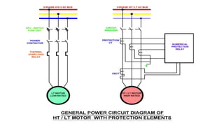
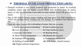
ELECTRICAL HT/LT
MOTOR PROTECTION
- NISCHAL POPAT
 THERMAL OVER LOAD PROTECTION (49/51)
• Thermal overload is very much essential type protection in motor. In overload
condition, motor will take higher current (More than its FLC) from its source
panel, so why this protection is provided on main control circuit OR power line of
motor.
• Due to this higher current, motor winding will heat up to very high temperature,
which can damage motor winding and can damage its insulation and lubrication
too.
• There are many reasons for overloading of motor, they are as under:
i. Due to mechanical overloading. ii. Due to pulsating load.
iii. Loss of cooling. iv. Clog ventilation ducts.
v. Improper lubrication. vi. Bearing failure.
vi. Motor-load misalignment. vii. Broken driving gear.
ix. Improper driving setting. x. Mechanical malfunction.
xi. Stalling of motor shaft. xii. OLR failure. (Small motors)
xiii. Higher ambient temperature.
• Electrical reasons, Like
xiv. Abnormal supply voltage. xv. Low power factor.
xvi. Abnormal winding resistance. (Motor winding get OPEN or SHORT
between phase-phase)
xvii. Poor insulation resistance. (Phase-Earth short)
• In LT motors overload relays are used to give protection against thermal overload,
where as HT motors are protected through numerical relay for overloading
condition.
• Principle of overload relay is very basic that if current will exceed from it sets
value in relay, relay will give trip command to interrupting device. (Some time
delay may be provided, depending upon OLR use)
• Currently common logic for thermal overload trip in HT motors is, Numerical
relay provides multiple time constant thermal replicas for different operating
conditions of motor. Like start-up (Cooling) conditions, running overload
condition.
• During starting condition motor will take very high current, so in thermal curve a
provision is given that it will avoid false trip during starting condition.
• Relay is using one algorithm to calculate tripping time of motor in thermal
overload condition. This algorithm will include initial state of motor so that
tripping time for hot condition of motor will decrease.
• After completion of time delay (From thermal graph) relay will give trip command
to interrupting device and motor will get stop.
 SHORT CIRCUIT PROTECTION (50):
• Short circuit fault in motor happens due to stator winding failure, or may be if iron
core get damaged, this condition leads to flow of heavy current in one or more
phase of motor.
• This condition in motor may need to detect immediately and trip from supply as
soon as possible otherwise motor will get more damage.
• Reasons of short circuit in motor:
i. Insulation failure. ii. Motor ageing.
iii. Mechanical stress. iv. Overheating.
v. Low supply voltage (Leads to high current flow).
vi. Repeated starting of motor.
• All this above condition can create below abnormal things in motor and short
circuit fault happens in motor.
i. Inter turn-turn short (Same phase) ii. Coil-coil short (Same phase)
iii. Coil-ground short iv. Phase-phase short
v. Phase-ground fault vi. Iron core damage
• Short circuit fault in motor is detected by numerical relay, whenever current in
motor will go beyond its setting, relay will give trip command to interrupting
device and motor will stop.
• Generally multi stage short circuit settings are used in numerical relay, Like
IDMT, DMT Etc.
• In relay short circuit tripping setting should be above maximum locked rotor
current of motor.
 STALL DETECTION IN MOTOR (48)
• In stall condition of motor, motor draws maximum current from source. Stall
condition of motor is when motor is applying maximum torque OR unable to
rotate and it draws maximum current.
• This condition rises when motor is prevented from entirely running, due to any
problem sudden obstruction on load arise, due to problem in motor.
• When motor speed decrease to very low value OR stop completely due to stalling,
slip of motor will increase and due to this higher voltage and higher current will be
induced into rotor winding and stator current also increases same.
• This higher current will heat rotor and can damage motor winding too.
• Stall condition in motor is also known as locked rotor of motor, because it is
equivalent to transformer whose secondary is shorted.
• So why it is very much essential to protect motor against stall condition.
• For very much lower rated motor, no provision is given for protection against stall
condition. But LT& HT motor stall condition is detected by numerical relay.
• Numerical relay is continuously monitor motor current and its speed, if motor take
higher amount of current at lower speed then relay will activate tripping command
for interrupting device and it will trip motor.
 PROLONGED START OF MOTOR:
• In numerical relay three criteria are used to detect motor start.
(A). Change in the interrupting device position is detected, Circuit breaker
position from OPEN to CLOSE. (52a)
(B). Detection of a starting current of more than the starting current
threshold. (I)
(C). 52a+I. (Both condition)
• Generally 52a+I condition used in numerical relay.
• After detection of motor start, to detect stalling relay used two conditions.
i. Time:
• While starting motor, it draws higher current so for successful start of motor -
STALL TIME < START TIME.
ii. Speed and current:
• Sometime condition may arise that motor which used for high inertia load,
successfully clears stall withstand time, without result in over temperature.
• For this problem, speed sensing device is mounted on motor and its contacts are
given to specified opto input of relay.
• Change in state of this contact indicates successful acceleration of motor.
• If line current value increases beyond set starting current value and at that time
motor speed is zero, then relay will give trip command with programmed stall
time.
 STALL DURING RUNNING:
• In running condition, if the current fails to fall below the current threshold before
the rotor stall time delay has elapsed, a trip command will be initiated.
 LIMIT NB STARTS (66):
• Any motor has a restriction on the number of starts that are allowed in a defined
period without the permitted winding temperatures being exceeded.
• Two types of starts are supervised by numerical relay:
• i. COLD START OF MOTOR:
• Cold start of motor is initial start of motor.
• In cold condition, motor’s stator & rotor temperature is below ambient
temperature, and start at this condition is called cold start of motor, once it stops
and again it can start as per no. of settings in numerical relay.
• Generally with reference of motor data sheet, no. of start per hour or per define
time is set in numerical relay.
• As frequent start can damage the motor winding and insulation, and it will reduce
motor life so no. start limit is provided as protection part of relay.
• Once no. of starts in define time are reached to its limit, relay will initiate start
inhibit, and it will not allow to restart motor until its inhibition time get completed.
ii. HOT START OF MOTOR
• Generally hot start is restart after motor coasting to stop means after recent full
load operation of motor, if it starts again it’s called hot start.
• Hot condition of motor is, motor’s stator & rotor temperature is above ambient
temperature.
• If Motor trips on Thermal overload protection, and it again started in some
interval, This start will also count as hot start.
• Further start of hot motor can leads to damage motor, because subsequent start
will increase temperature of motor, which can damage insulation and winding too.
• The motor protection relay generally prevents motor damage by limiting the
number of start per hour or per defines time.
• It will follow same principle as in cold start that when no. of starts in define time
are reached to its limit, relay will initiate start inhibit, and it will not allow to
restart motor until its inhibition time get completed.
• Numbers of total starts are detected from 52a (Breaker start contacts)
 NEGATIVE PHASE SEQUENCE PROTECTION (46):
• Negative phase sequence in motor happens due to unbalance supply voltage that is
applied on stator.
• Whenever supply voltage get abnormal, positive sequence component value will
reduce and due to this value of deliver power to motor will reduce. Due to this
condition negative sequence voltage will induce in rotor winding and abnormal
current will flow through it because rotor is short circuited.
• This abnormality can damage rotor winding and motor too.
• Reasons that create negative phase sequence current in motor are as under:
i. Phase reversal. ii. Supply voltage unbalance.
iii. Single phasing.
• This protection is provided by numerical relay.
 UNDER VOLTAGE PROTECTION (27):
• In power system low voltage condition occur due to more demand of load, or it
may happen due to other abnormal conditions. But motor supplied voltage should
not go beyond its limit (As mention in name plate of motor) otherwise it can
damage motor.
• Whenever moor supplied in low voltage condition, at that time suddenly torque on
motor get reduce about 20%, now if motor carries light load it might not get
affected by it but if motor is on loading condition, then it will try to maintain
torque, so motor will take higher current from its source, due to which winding
will heat up and it can damage insulation and winding due to which motors life
goes reduce.
• This is what reason that motor should be protected from under voltage condition.
 OVER VOLTAGE PROTECTION (59):
• Over voltage in motor occurs whenever it is supplied beyond its rated voltage.
• This condition must need to identify immediately as overvoltage creates stress on
insulation, which affects on motor’s life.
• Due to over voltage magnetizing current in motor increases and this will increase
iron loss of motor, due to which winding will heat up. However load current will
be reduce as voltage increases also sleep will decrease, and motor efficiency will
also increase slightly.
• Overvoltage in motor is protected through numerical relay.
 SENSITIVE EARTH FAULT PROTECTION
(50NS/51NS):
• Sensitive earth fault protection is used to provide protection against earth fault in
motor.
• In sensitive earth fault type protection, core balance CT is used as protection CT,
which will continuously monitor all phase current and measure residual current.
• In normal condition residual current (Zero sequence current) will be zero, as
current flowing in all phase is same, so magnetic flux in all phase are also same,
and it will cancel each other. (as per CBCT working principle)
• IR + IY + IB = 0
• Suppose earth fault happen in any of phase than zero sequence current will not be
cancel and some amount of current will flow in CT secondary, and so how relay
will give trip command, and motor coasting to stop.
• Sensitive relay can identify 2% of earth fault.
Electrical HT/LT Motor protection

Electrical HT/LT Motor protection

  • 1.
  • 3.
     THERMAL OVERLOAD PROTECTION (49/51) • Thermal overload is very much essential type protection in motor. In overload condition, motor will take higher current (More than its FLC) from its source panel, so why this protection is provided on main control circuit OR power line of motor. • Due to this higher current, motor winding will heat up to very high temperature, which can damage motor winding and can damage its insulation and lubrication too. • There are many reasons for overloading of motor, they are as under: i. Due to mechanical overloading. ii. Due to pulsating load. iii. Loss of cooling. iv. Clog ventilation ducts. v. Improper lubrication. vi. Bearing failure. vi. Motor-load misalignment. vii. Broken driving gear. ix. Improper driving setting. x. Mechanical malfunction. xi. Stalling of motor shaft. xii. OLR failure. (Small motors) xiii. Higher ambient temperature.
  • 4.
    • Electrical reasons,Like xiv. Abnormal supply voltage. xv. Low power factor. xvi. Abnormal winding resistance. (Motor winding get OPEN or SHORT between phase-phase) xvii. Poor insulation resistance. (Phase-Earth short) • In LT motors overload relays are used to give protection against thermal overload, where as HT motors are protected through numerical relay for overloading condition. • Principle of overload relay is very basic that if current will exceed from it sets value in relay, relay will give trip command to interrupting device. (Some time delay may be provided, depending upon OLR use) • Currently common logic for thermal overload trip in HT motors is, Numerical relay provides multiple time constant thermal replicas for different operating conditions of motor. Like start-up (Cooling) conditions, running overload condition.
  • 5.
    • During startingcondition motor will take very high current, so in thermal curve a provision is given that it will avoid false trip during starting condition. • Relay is using one algorithm to calculate tripping time of motor in thermal overload condition. This algorithm will include initial state of motor so that tripping time for hot condition of motor will decrease. • After completion of time delay (From thermal graph) relay will give trip command to interrupting device and motor will get stop.
  • 6.
     SHORT CIRCUITPROTECTION (50): • Short circuit fault in motor happens due to stator winding failure, or may be if iron core get damaged, this condition leads to flow of heavy current in one or more phase of motor. • This condition in motor may need to detect immediately and trip from supply as soon as possible otherwise motor will get more damage. • Reasons of short circuit in motor: i. Insulation failure. ii. Motor ageing. iii. Mechanical stress. iv. Overheating. v. Low supply voltage (Leads to high current flow). vi. Repeated starting of motor.
  • 7.
    • All thisabove condition can create below abnormal things in motor and short circuit fault happens in motor. i. Inter turn-turn short (Same phase) ii. Coil-coil short (Same phase) iii. Coil-ground short iv. Phase-phase short v. Phase-ground fault vi. Iron core damage
  • 8.
    • Short circuitfault in motor is detected by numerical relay, whenever current in motor will go beyond its setting, relay will give trip command to interrupting device and motor will stop. • Generally multi stage short circuit settings are used in numerical relay, Like IDMT, DMT Etc. • In relay short circuit tripping setting should be above maximum locked rotor current of motor.
  • 9.
     STALL DETECTIONIN MOTOR (48) • In stall condition of motor, motor draws maximum current from source. Stall condition of motor is when motor is applying maximum torque OR unable to rotate and it draws maximum current. • This condition rises when motor is prevented from entirely running, due to any problem sudden obstruction on load arise, due to problem in motor. • When motor speed decrease to very low value OR stop completely due to stalling, slip of motor will increase and due to this higher voltage and higher current will be induced into rotor winding and stator current also increases same. • This higher current will heat rotor and can damage motor winding too. • Stall condition in motor is also known as locked rotor of motor, because it is equivalent to transformer whose secondary is shorted. • So why it is very much essential to protect motor against stall condition. • For very much lower rated motor, no provision is given for protection against stall condition. But LT& HT motor stall condition is detected by numerical relay.
  • 10.
    • Numerical relayis continuously monitor motor current and its speed, if motor take higher amount of current at lower speed then relay will activate tripping command for interrupting device and it will trip motor.
  • 11.
     PROLONGED STARTOF MOTOR: • In numerical relay three criteria are used to detect motor start. (A). Change in the interrupting device position is detected, Circuit breaker position from OPEN to CLOSE. (52a) (B). Detection of a starting current of more than the starting current threshold. (I) (C). 52a+I. (Both condition) • Generally 52a+I condition used in numerical relay. • After detection of motor start, to detect stalling relay used two conditions.
  • 12.
    i. Time: • Whilestarting motor, it draws higher current so for successful start of motor - STALL TIME < START TIME.
  • 13.
    ii. Speed andcurrent: • Sometime condition may arise that motor which used for high inertia load, successfully clears stall withstand time, without result in over temperature. • For this problem, speed sensing device is mounted on motor and its contacts are given to specified opto input of relay. • Change in state of this contact indicates successful acceleration of motor. • If line current value increases beyond set starting current value and at that time motor speed is zero, then relay will give trip command with programmed stall time.  STALL DURING RUNNING: • In running condition, if the current fails to fall below the current threshold before the rotor stall time delay has elapsed, a trip command will be initiated.
  • 14.
     LIMIT NBSTARTS (66): • Any motor has a restriction on the number of starts that are allowed in a defined period without the permitted winding temperatures being exceeded. • Two types of starts are supervised by numerical relay: • i. COLD START OF MOTOR: • Cold start of motor is initial start of motor. • In cold condition, motor’s stator & rotor temperature is below ambient temperature, and start at this condition is called cold start of motor, once it stops and again it can start as per no. of settings in numerical relay. • Generally with reference of motor data sheet, no. of start per hour or per define time is set in numerical relay. • As frequent start can damage the motor winding and insulation, and it will reduce motor life so no. start limit is provided as protection part of relay.
  • 15.
    • Once no.of starts in define time are reached to its limit, relay will initiate start inhibit, and it will not allow to restart motor until its inhibition time get completed. ii. HOT START OF MOTOR • Generally hot start is restart after motor coasting to stop means after recent full load operation of motor, if it starts again it’s called hot start. • Hot condition of motor is, motor’s stator & rotor temperature is above ambient temperature. • If Motor trips on Thermal overload protection, and it again started in some interval, This start will also count as hot start. • Further start of hot motor can leads to damage motor, because subsequent start will increase temperature of motor, which can damage insulation and winding too. • The motor protection relay generally prevents motor damage by limiting the number of start per hour or per defines time.
  • 16.
    • It willfollow same principle as in cold start that when no. of starts in define time are reached to its limit, relay will initiate start inhibit, and it will not allow to restart motor until its inhibition time get completed. • Numbers of total starts are detected from 52a (Breaker start contacts)
  • 17.
     NEGATIVE PHASESEQUENCE PROTECTION (46): • Negative phase sequence in motor happens due to unbalance supply voltage that is applied on stator. • Whenever supply voltage get abnormal, positive sequence component value will reduce and due to this value of deliver power to motor will reduce. Due to this condition negative sequence voltage will induce in rotor winding and abnormal current will flow through it because rotor is short circuited. • This abnormality can damage rotor winding and motor too. • Reasons that create negative phase sequence current in motor are as under: i. Phase reversal. ii. Supply voltage unbalance. iii. Single phasing. • This protection is provided by numerical relay.
  • 18.
     UNDER VOLTAGEPROTECTION (27): • In power system low voltage condition occur due to more demand of load, or it may happen due to other abnormal conditions. But motor supplied voltage should not go beyond its limit (As mention in name plate of motor) otherwise it can damage motor. • Whenever moor supplied in low voltage condition, at that time suddenly torque on motor get reduce about 20%, now if motor carries light load it might not get affected by it but if motor is on loading condition, then it will try to maintain torque, so motor will take higher current from its source, due to which winding will heat up and it can damage insulation and winding due to which motors life goes reduce. • This is what reason that motor should be protected from under voltage condition.
  • 19.
     OVER VOLTAGEPROTECTION (59): • Over voltage in motor occurs whenever it is supplied beyond its rated voltage. • This condition must need to identify immediately as overvoltage creates stress on insulation, which affects on motor’s life. • Due to over voltage magnetizing current in motor increases and this will increase iron loss of motor, due to which winding will heat up. However load current will be reduce as voltage increases also sleep will decrease, and motor efficiency will also increase slightly. • Overvoltage in motor is protected through numerical relay.
  • 20.
     SENSITIVE EARTHFAULT PROTECTION (50NS/51NS): • Sensitive earth fault protection is used to provide protection against earth fault in motor. • In sensitive earth fault type protection, core balance CT is used as protection CT, which will continuously monitor all phase current and measure residual current. • In normal condition residual current (Zero sequence current) will be zero, as current flowing in all phase is same, so magnetic flux in all phase are also same, and it will cancel each other. (as per CBCT working principle) • IR + IY + IB = 0 • Suppose earth fault happen in any of phase than zero sequence current will not be cancel and some amount of current will flow in CT secondary, and so how relay will give trip command, and motor coasting to stop. • Sensitive relay can identify 2% of earth fault.