1. The document discusses high voltage testing of electrical transformers, including various types of tests like partial discharge testing, impulse testing, turns ratio testing, and insulation resistance testing.
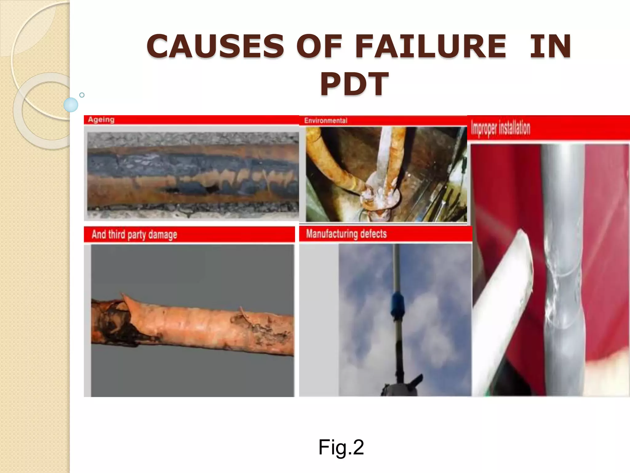
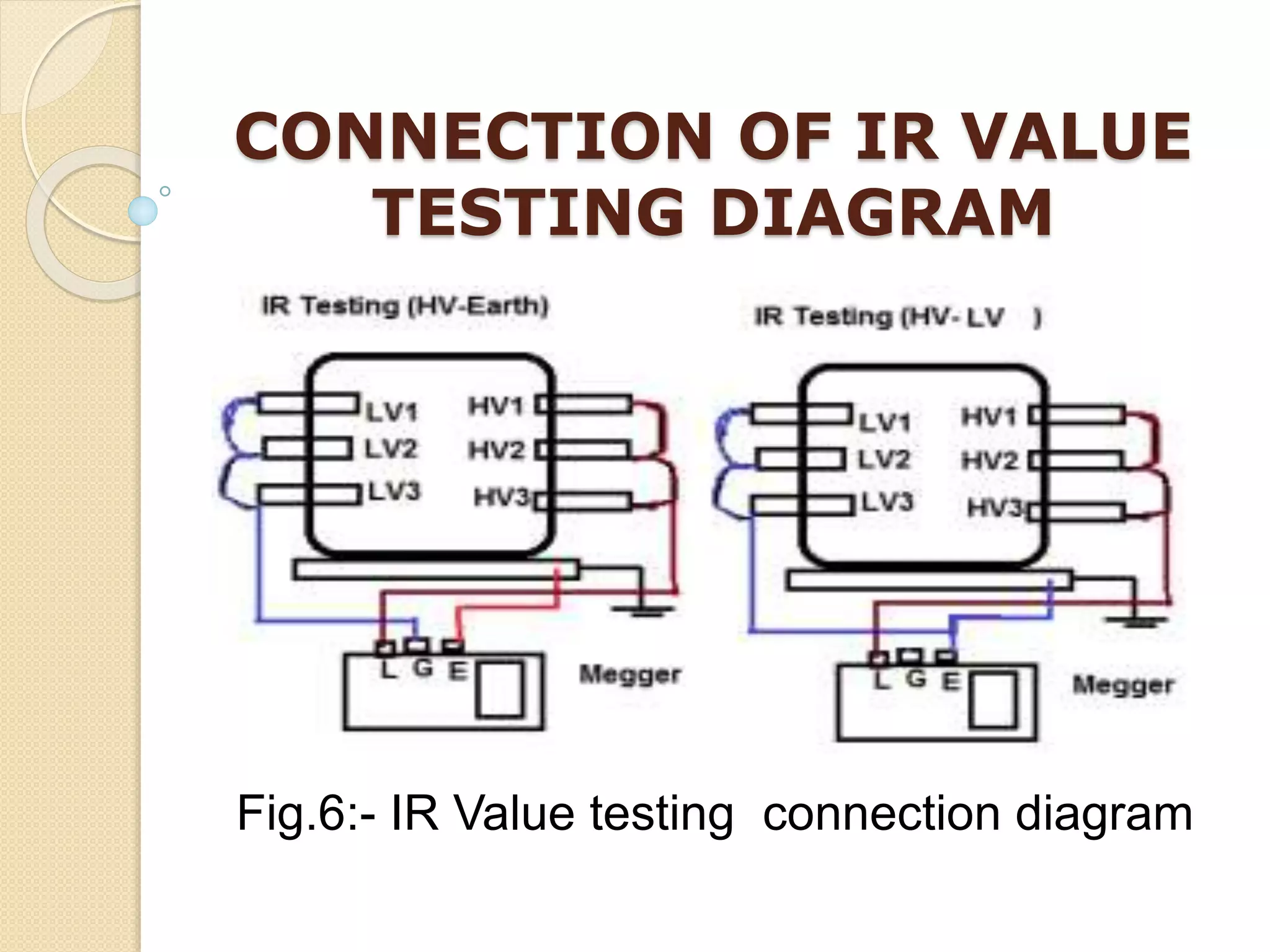
2. These tests help check the insulation quality, detect defects, verify voltage ratios, and ensure transformers can withstand high voltage surges to prevent failures.
3. High voltage testing provides advantages like improved safety, energy efficiency, lower costs, and failure detection; but can also have disadvantages like not removing the root causes of failures.
Test done on Power transformers.
Insulation Resistance test, Winding Resistance test, Ratio Measurements, Magnetic balance test, Tan delta test, DIssolved gas analysis for transformer, Sweep frequency response analysis.
Test done on Power transformers.
Insulation Resistance test, Winding Resistance test, Ratio Measurements, Magnetic balance test, Tan delta test, DIssolved gas analysis for transformer, Sweep frequency response analysis.
This PPT explains about the circuit breaker, and its types. Then about the need and purpose of the circuit breaker. And finally the testing and types of testing of circuit breakers.
Tan delta is the insulation power factor & is equal to the ratio of power dissipated in the insulation in watts to the product of effective voltage & current in volt ampere when tested under sinusoidal voltage.
This directional over current relay employs the principle of actuation of the relay....It has a metallic disc free to rotate between the poles of two...
Unit I: Introduction to Protection System:
Introduction to protection system and its elements, functions of protective relaying, protective zones, primary and backup protection, desirable qualities of protective relaying, basic terminology.
Relays:
Electromagnetic, attracted and induction type relays, thermal relay, gas actuated relay, design considerations of electromagnetic relay.
Unit-II: Relay Application and Characteristics:
Amplitude and phase comparators, over current relays, directional relays, distance relays, differential relay.
Static Relays: Comparison with electromagnetic relay, classification and their description, over current relays, directional relay, distance relays, differential relay.
Unit-III Protection of Transmission Line:
Over current protection, distance protection, pilot wire protection, carrier current protection, protection of bus, auto re-closing,
Unit-IV: Circuit Breaking:
Properties of arc, arc extinction theories, re-striking voltage transient, current chopping, resistance switching, capacitive current interruption, short line interruption, circuit breaker ratings.
Testing Of Circuit Breaker: Classification, testing station and equipments, testing procedure, direct and indirect testing.
Unit-V Apparatus Protection:
Protection of Transformer, generator and motor.
Circuit Breaker: Operating modes, selection of circuit breakers, constructional features and operation of Bulk Oil, Minimum Oil, Air Blast, SF6, Vacuum and d. c. circuit breakers.
Insulation resistance measurements are performed to verify that the state of dryness of the insulation of the various Winding , Bushings and the core are of acceptable values. In these presentation we will discuss about basic Insulation resistance test carried out in a two winding transformer.
About Transmission Line.
Transmission Lines
Classification Of Transmission Lines
Overhead Power Line
Advantages Of Overhead Transmission Lines
Disadvantages Of Overhead Transmission Lines
Nominal “T” Method
Nominal “Pi” Model of a Medium Transmission Line
Underground Transmission Lines
Classification Of Underground Cables
Advantages Of Underground Cables
Disadvantages Of Underground Cables
How is power transformer protected??? This provides a basic understanding of power transformer. Furthermore, the protective relay application on power transformer is included.
Partial Discharge Detection Products by EA TechnologyRyan McFallo
EA Technology is the global leader in MV Partial Discharge detection. EA’s unique technology allows real time partial discharge detection and monitoring without interrupting service, EA also provides on-site partial discharge surveys.
Would you like to learn more about partial discharge detection and monitoring products/services?
Visit Technical Sales-Northwest at http://www.techsalesnw.com
Installation, Testing and Troubleshooting of TransformersLiving Online
This will provide you with practical knowledge (including tips, tricks and tools) covering the fundamentals of power transformers and their testing. It will greatly assist you in communicating more effectively with your electrical engineering colleagues. At the end of this workshop, participants will be familiar with the importance of transformer testing and their purpose, the different kinds of transformer tests and their procedures and the practical applications of principals applied in transformer operation and maintenance.
WHO SHOULD ATTEND?
This workshop will be appropriate for the following professionals:
Electrical engineers
Maintenance engineers
Maintenance supervisors
Power electricians
Power engineers
MORE INFORMATION: http://www.idc-online.com/content/installation-testing-and-troubleshooting-transformers-24
The purpose of the test is to secure that the transformer insulations withstand the lightning overvoltages which may occur in service.The testing is conducted by artificial generation oflightning impulse using IMPULSe GENERATORS
It is very useful power point presentation on the "Grid Voltage Regulation"
it consist all thing related with topic.
I have already presented and got 100% credit.
VTU Notes for Testing and commissioning of Electrical Equipment Department of Electrical and Electronics Faculty Name: Mrs Veena Bhat Designation: Assistant Professor Subject: Testing and Commissioning of Electrical equipment Semester: VII
Module 2 ee369 KTU syllabus-high voltage ac generation,resonant circuitsAsha Anu Kurian
Generation of high AC voltages-Testing transformer – single unit testing transformer, cascaded transformer – equivalent circuit of cascaded transformer – generation of high frequency AC voltages- series resonance circuit – resonant transformer – voltage regulation.
High Tension Current Transformer in Punebizproto26
We are recognized as a successful manufacturers, exporters and traders of Current Transformers. It is a static machine used for transforming power from one circuit to another without changing frequency. Current Transformers is generally used in transmission network which is normally known as power transformer, distribution transformer is used in distribution network and this is lower rating transformer and current transformer & potential transformer, we use for relay and protection purpose in electrical power system and in different instruments in industries are called instrument transformer.
HIGH VOL TAGE TESTING OF TRANSFORMER BY HARI SHANKAR SINGH
1. Seminar guide Seminar coordinator
Ms. Aanchal Baranwal Mr. Alok pandey
(Assistant professor) (Assistant professor)
Department of Electrical Department of Electrical
Engineering Engineering
A
Seminar
on
High voltage testing of
Electrical Transformer
PRESENTED BY
Hari Shankar Singh:-1308220902
2. CONTENTS
Introduction of transformer and HV transformer
Types of testing of transformer and explain with
detail
Advantages of HV testing of transformer
Disadvantages of HV testing of transformer
Conclusion
References
3. What is Transformer ?
• Transformer is an electrostatic device which
transfer electrical energy one circuit to another
circuit by magnetic flux without change of
frequency . Transformer has based on principle
of electromagnetic induction(EMI).
• Formula used as measured a value,
Vs / V p = Ns / N p = I p / Is
4. HIGH VOLTAGE
TRANSFORMER
• High voltage transformers convert voltages from
one level or phase configuration to another,
usually from higher to lower.
• They can include features for electrical isolation,
power distribution, and control and
instrumentation applications.
• High voltage transformers usually depend on
the principle of magnetic induction between
coils to convert voltage and current levels .
5. TYPES OF HV TESTING OF
ELECTRICAL TRANSFORMER
1. Partial discharge test
2. Impulse transformer test
3. Transformer turns ratio test
4. Insulation resistance test
5. Routine test
6. Temperature rise of oil testing of transformer
6. PARTIAL DISCHARGE TEST
• Partial discharge is a small localised dielectric
breakdown of an electrical insulation system
under high voltage stress.
• Each discrete partial discharge is the result of an
electrical breakdown of an air pocket within the
insulation.
• These discharges erode insulation and
eventually result in insulation failure.
7. • Acoustic techniques are used by manufacturers
to locate discharges that occur during HV testing
factory.
• PD occurs if the electric field strength applied to
a dielectric exceeds the dielectric withstand
strength of an insulation system locally.
• This may be caused by either increased field
strengths , e.g. due to design problems, sharp
edges on electrodes, small clearances , ageing ,
manufacture defect , insulation failure , damage
etc.
11. FUTURE APPLIANCES FROM
PDT
• Cables and Power transformers and bushings.
• Switchgear.
• Motors and generators
• Conclusion PDT testing prevents failure,
1. Off-line testing is a critical pre-commissioning
check.
2. On- line testing is an extremely powerful non-
instructive condition monitoring tool.
12. IMPULSE TRANSFORMER
TEST
• This test is made to prove that the transformer
insulation will withstand voltage surges which
may be caused by lightning or switching.
• This includes insulation to ground, insulation
between turns and windings, and the flashover
value of the associated bushings.
• A high-voltage wave of standard values, and
approximating a lightning surge, is imposed on
the unit to be tested.
13. • By a lightning pulse method used as measured
for impulse transformer testing followed as full
wave, half wave and front of wave show in Fig.4.
Fig.4:- Graph between ultra frequency and time
15. TRANSFORMER TURN’S
RATIO TEST
• The Transformer Turns Ratio test is used to
make sure that the Turns Ratio between the
winding of the transformer is correct.
• With this information, you can decide what the
output voltage of the transformer will be. The
ratio is calculated under no-load conditions using
formula given below,
V pri /V sec = Z pri/ Z sec = (N pri /N sec )2
16. INSULATION RESISTANCE
TEST
(IR VALUE TEST)
• Insulation ages and deteriorates because of
moisture, dust and electrostatic stress. Insulation
should be monitored continually to avoid sudden
failure of the equipment.
• An insulation resistance test detects insulation
quality within the transformer.
• The conductive impurities or mechanical flows in
the dielectric can be analysis based on this test.
17. CONNECTION OF IR VALUE
TESTING DIAGRAM
Fig.6:- IR Value testing connection diagram
18. • Normally, MEGGERS have a test voltage of
500V , 2500V , or 5000V .
• IR between HV and LV as well as windings to
earth.
• Minimum IR value for Tap changer is 1000 ohm
per volt service voltage
19. FACTORS AFFECTING ON IR
VALUE OF TRANSFORMER
• The IR value of transformers are influenced by
Surface condition of the terminal bushing.
• Quality of oil.
• Quality of winding insulation.
• Temperature of oil.
• Duration of application and value of test voltage.
20. IR VALUE TESTING
FORMULAS
• 1 Phase Transformer
IR Value (MΩ) = C X E / (√KVA)
• 3 Phase Transformer (Star)
IR Value (MΩ) = C X E (P-n) / (√KVA)
• 3 Phase Transformer(Delta)
IR Value (MΩ) = C X E (P-P) / (√KVA)
Where C= 1.5 for Oil filled T/C with Oil Tank,
30 for Oil filled T/C without Oil Tank or Dry Type T/C.
21. ROUTINE TEST FOR
TRANSFORMER
A Routine test of transformer is mainly for confirming
operational performance of individual unit in a
production lot. Routine tests are carried out on every
unit manufactured.
All transformers are subjected to the following
Routine tests:
• Insulation resistance Test.
• Winding resistance Test.
• Turns Ratio / Voltage ratio Test
22. • Polarity / Vector group Test
• Open circuit and short circuit Test.
• Continuity Test.
• High Voltage Test.
• Partial discharge Test.
• Separate source AC voltage.
• Induced overvoltage.
• Lightning impulse Tests.
• On -load tap changers Test.
23. TEMPERATURE OIL
TESTING OF TRANSFORMER
• Temperature rise test of oil of Transformer is
included in type test of transformer.
• In this test we check whether the temperature
rising limit of transformer winding and oil as per
specification or not.
• Faults detects at above 75˚C by the help of
Buchholz relay and work as ALARM and TRIP
circuit.
25. ADVANTAGES OF HV
TESTING TRANSFORMER
• Pure conductivity by IR Value test.
• Controlling of HV surges by Impulse test.
• Removing of discrete waveform by the help of
Partial Discharge test.
• Terminals has used connected correctly by
Transformer Turn’s Ratio test.
• Units measured a correctly and manufacturing
defect check by Routine test.
26. DISADVANTAGES OF HV
TESTING OF TRANSFORMER
• After failure, transformer is removed and
replaced with new/repaired one without removing
the cause of failure which results in immediate or
short time failure.
• Insufficient Oil level.
• Faulty operation of tap changer switch.
• Lack of installation checks.
• Prolonged Over loading.
27. CONCLUSION
• Knowledge of the construction of high voltage test
transformers, their design and use in high voltage
testing system gives the solution of the most
adjustment transformer in respect of parameters
and prices.
• HV testing are main advantages of safety ,
higher efficiency , lower cost ,savings of energy ,
avoiding of failures ,trouble shooting for failure
detection , accurate detection , quality assurance.
28. REFERENCES
• R.S. Jha, “High Voltage Engineering”, Dhanpat
Rai & Sons, Second Edition in 1996.
• C. L. Wadhwa, “High Voltage Engineering”, Wiley
Eastern Ltd. Third Edition in 2012.
• E.Kuffel and W.S. Zaengl, “High Voltage
Engineering” , Pergamon Press, First Edition
in1984.