Downloaded 260 times
![The condition begins
to deteriorate
Y
Z
The condition change
becomes detectable
Good Condition
X
The condition has
deteriorated to the
point of failure
Time
Failure
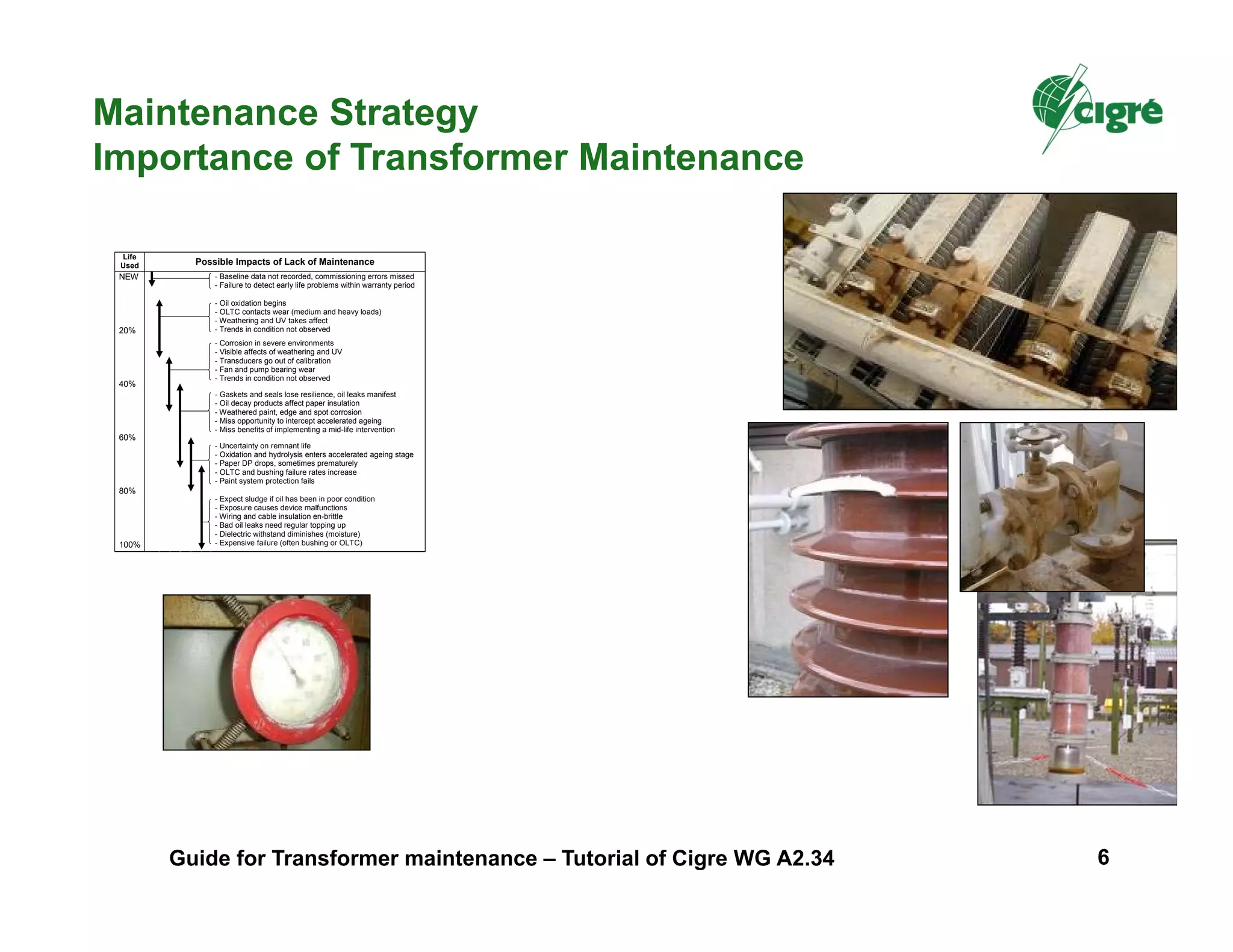
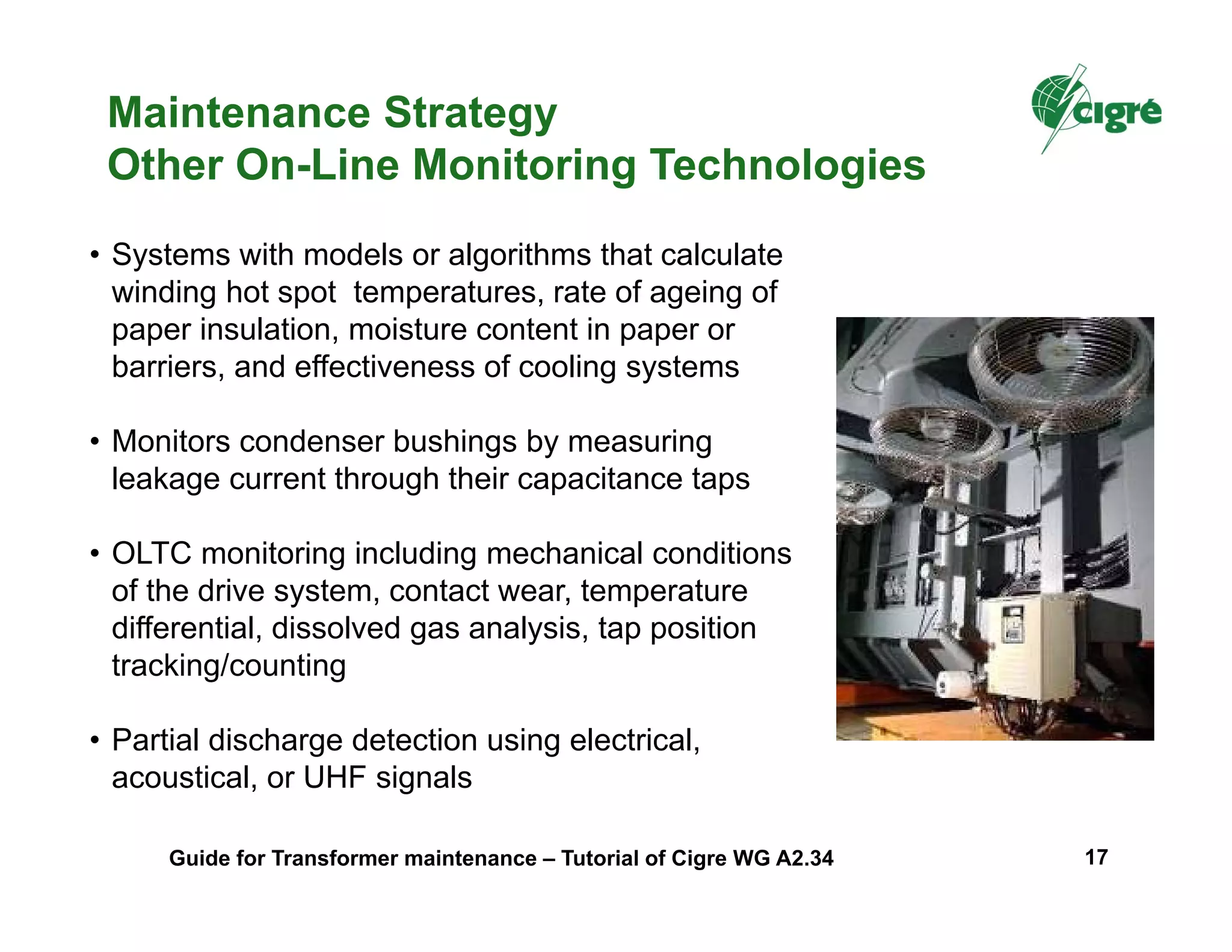
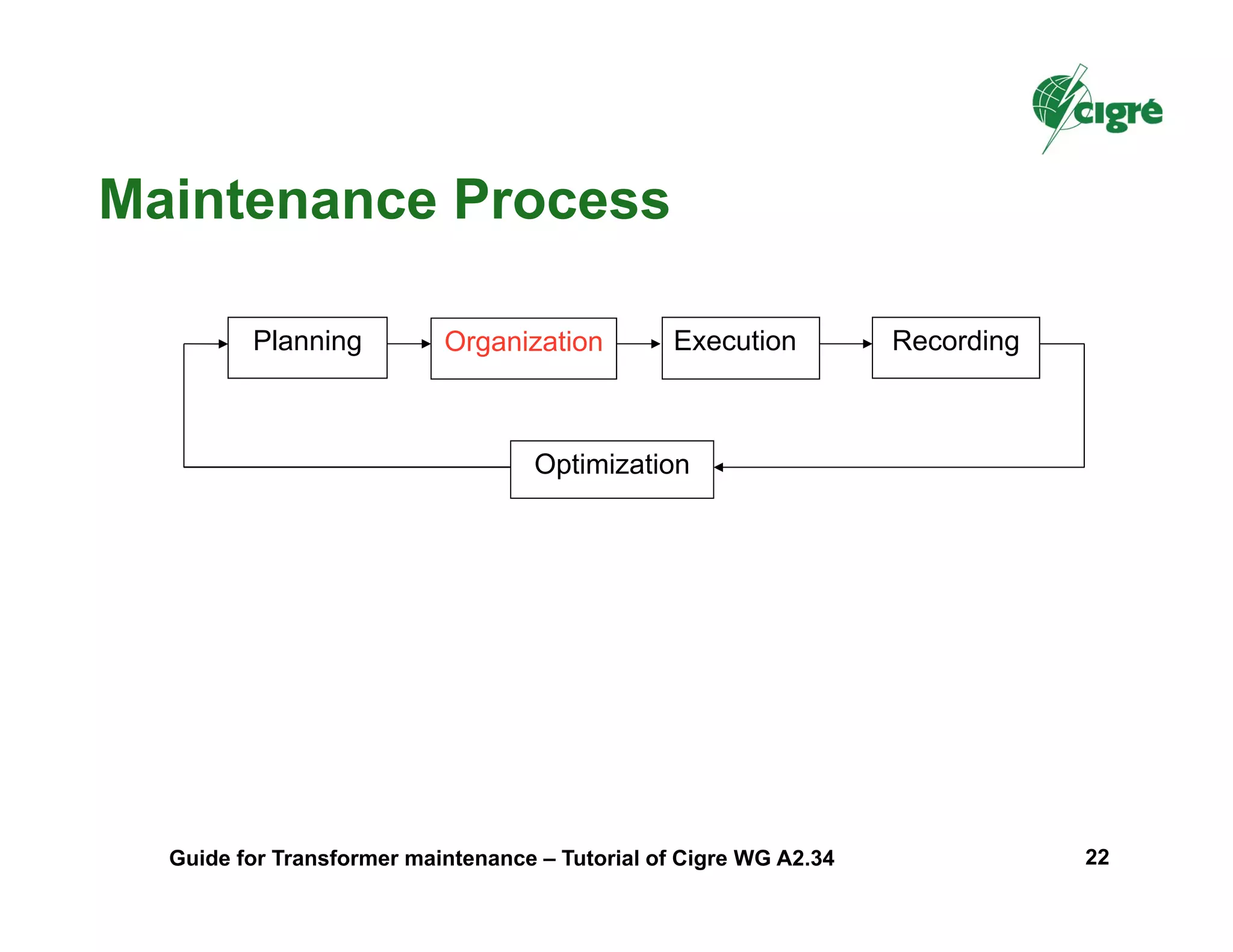
Maintenance Strategy
Theoretical Transformer Condition Degradation
- detect initial changes in condition that are relatively small compared
to the deterioration necessary for failure to occur
- have measurement or inspection intervals that are smaller than
∆T[XY]+∆T[YZ] to allow detection before failure occurs
- have a period of time ∆T[YZ] that is long enough to be able to take
the preventive action (ex: transformer outage)
To be technically feasible, a condition assessment task should have the ability to:
∆T[XY] ∆T[YZ]
Guide for Transformer maintenance – Tutorial of Cigre WG A2.34 7](https://image.slidesharecdn.com/a2-170718170238/75/A2-34-transformer-maintenance-tutorial-7-2048.jpg)
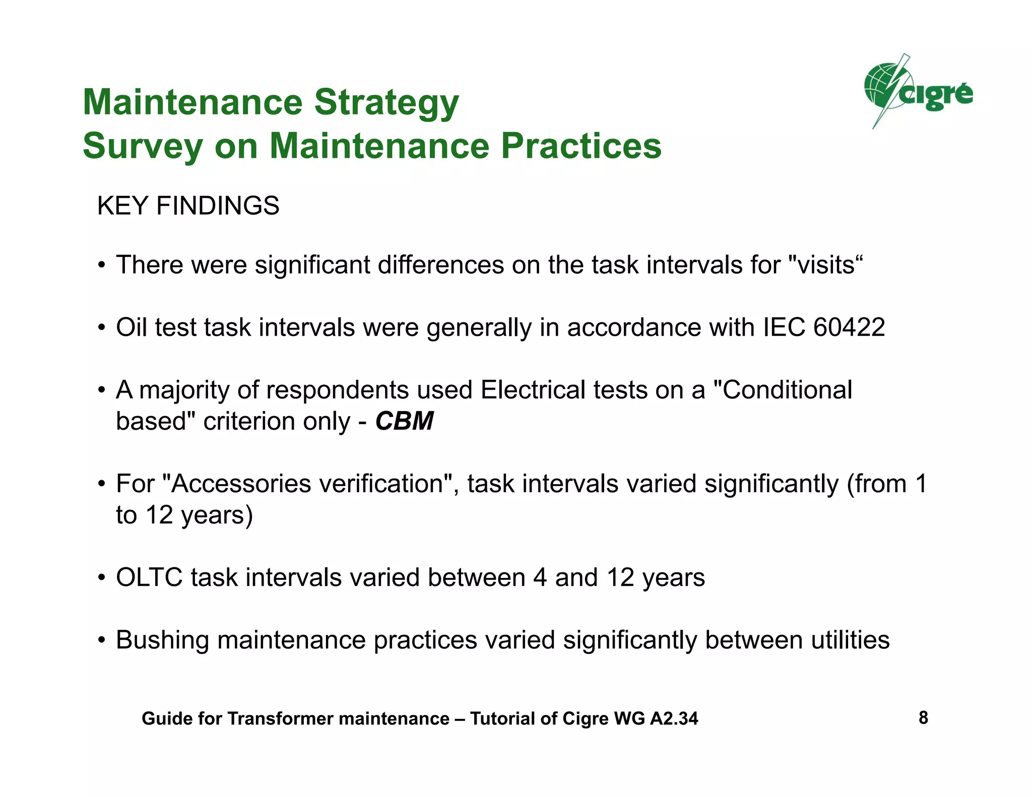
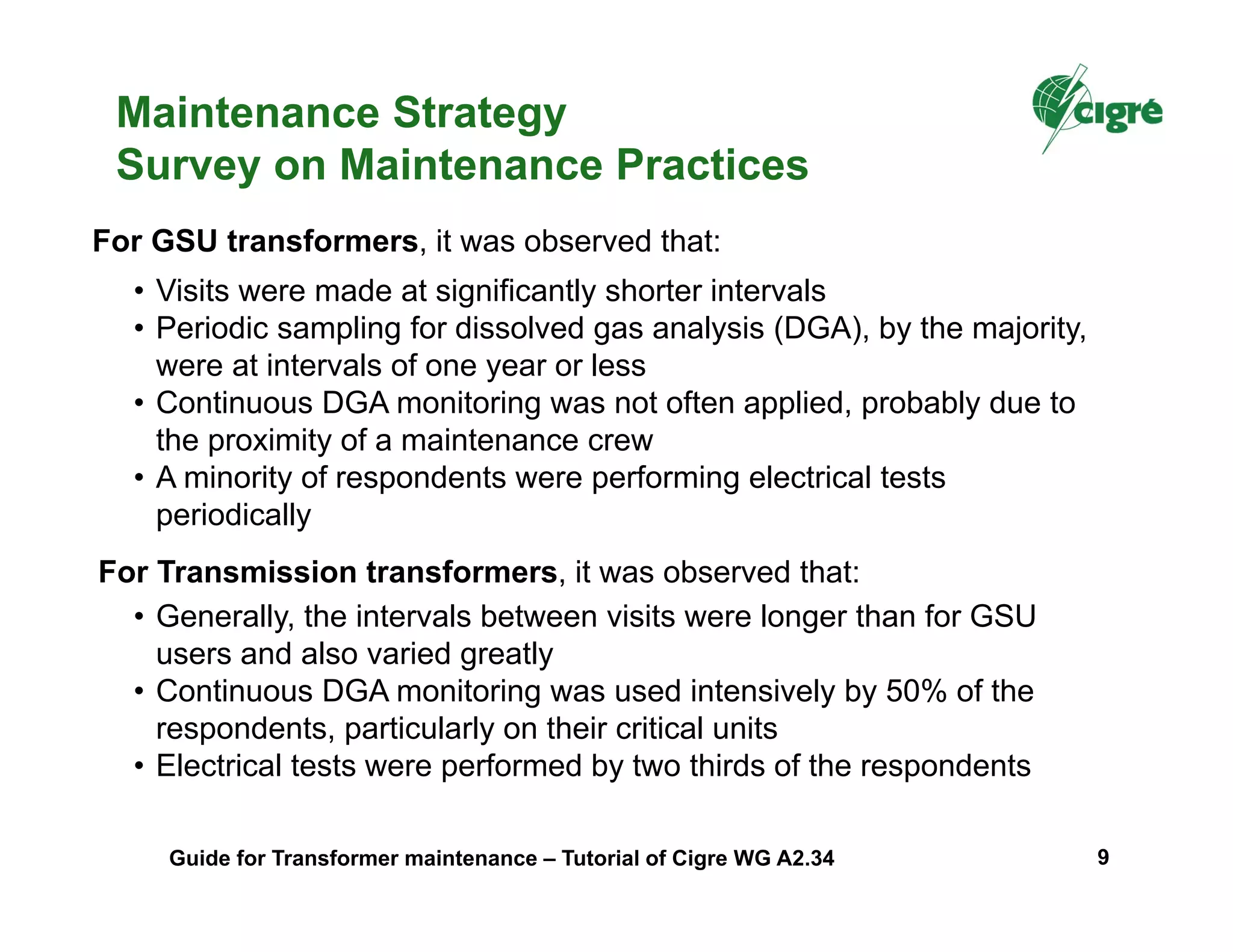
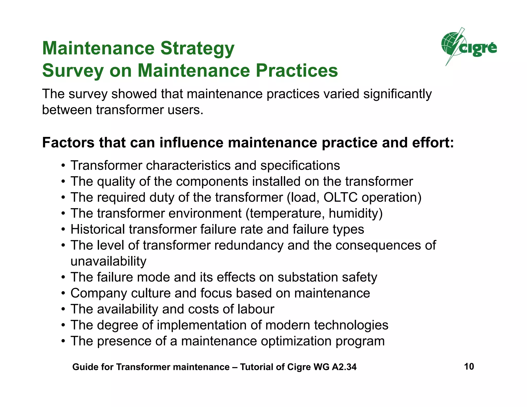
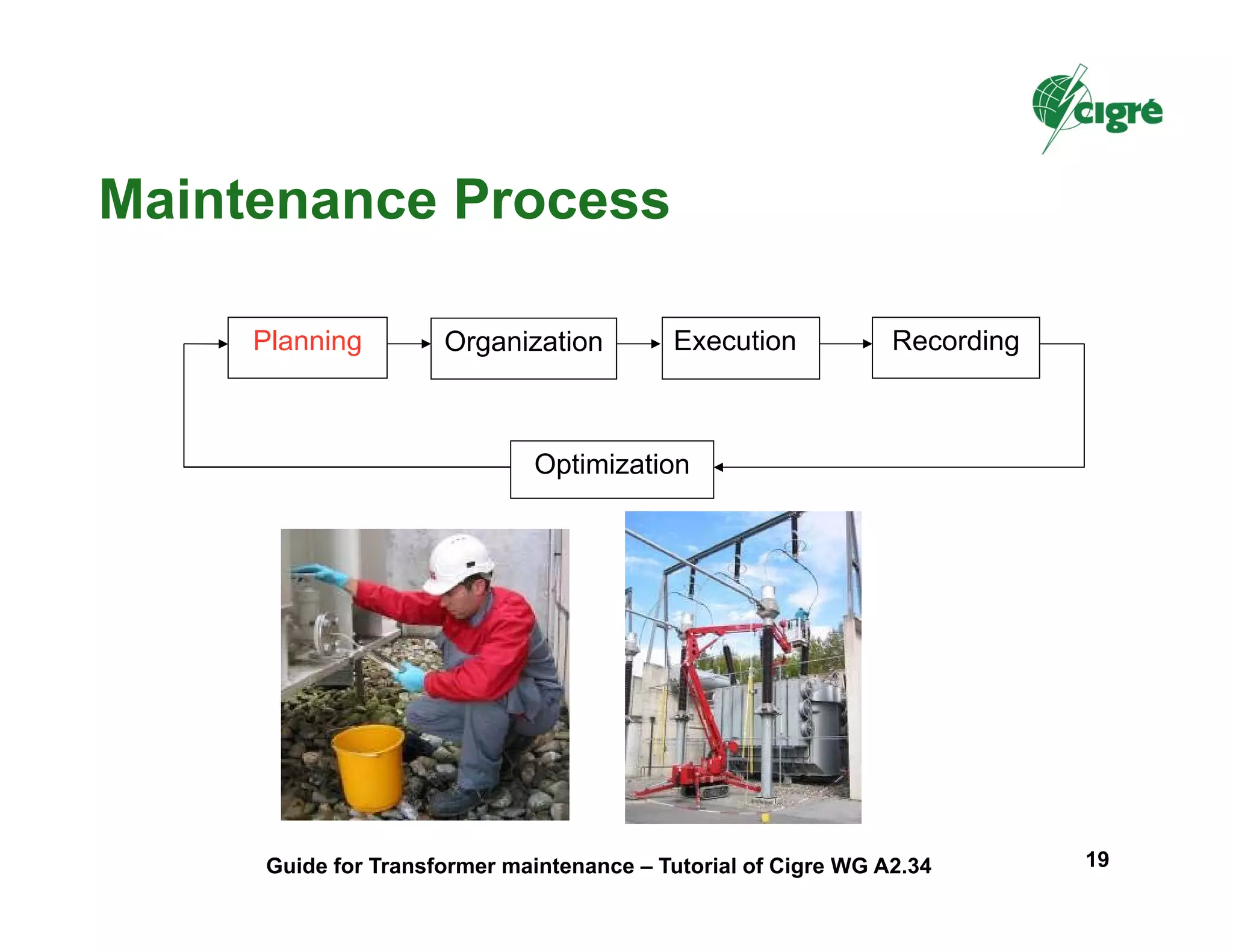

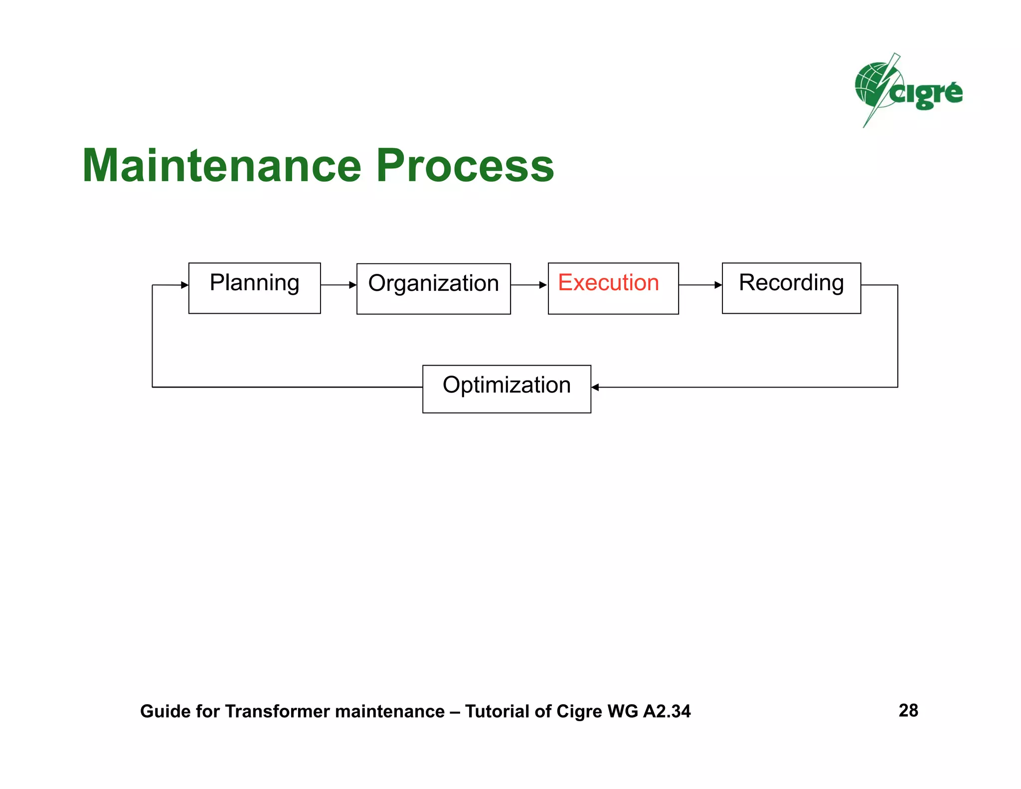

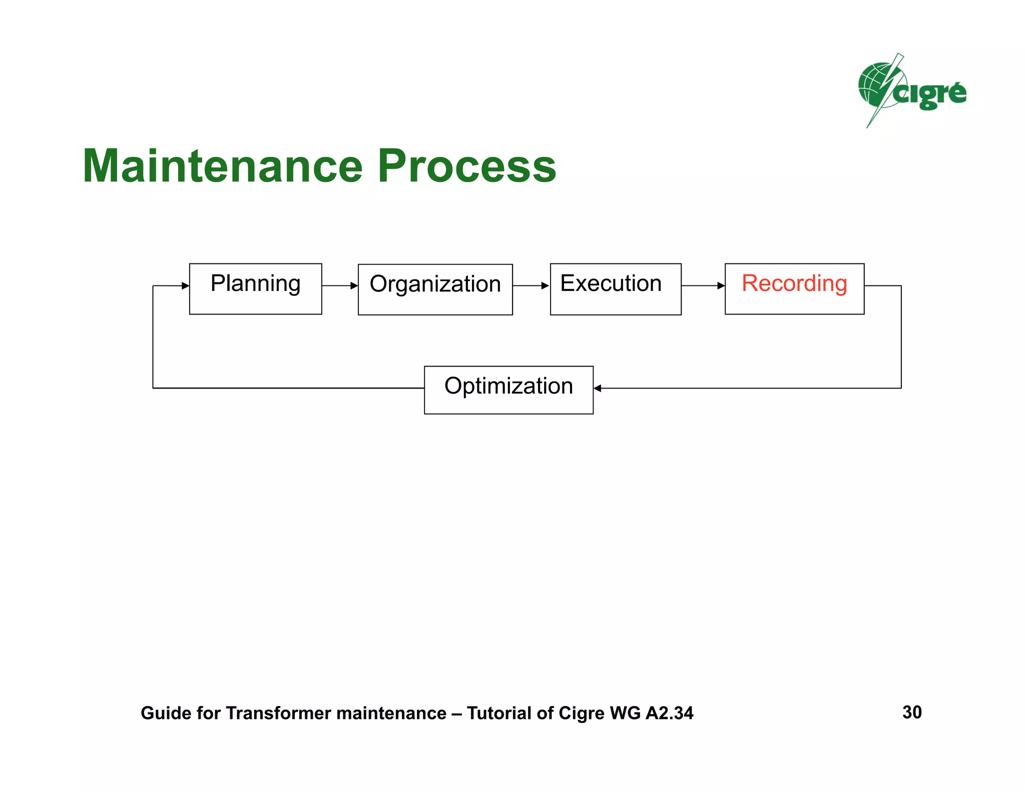
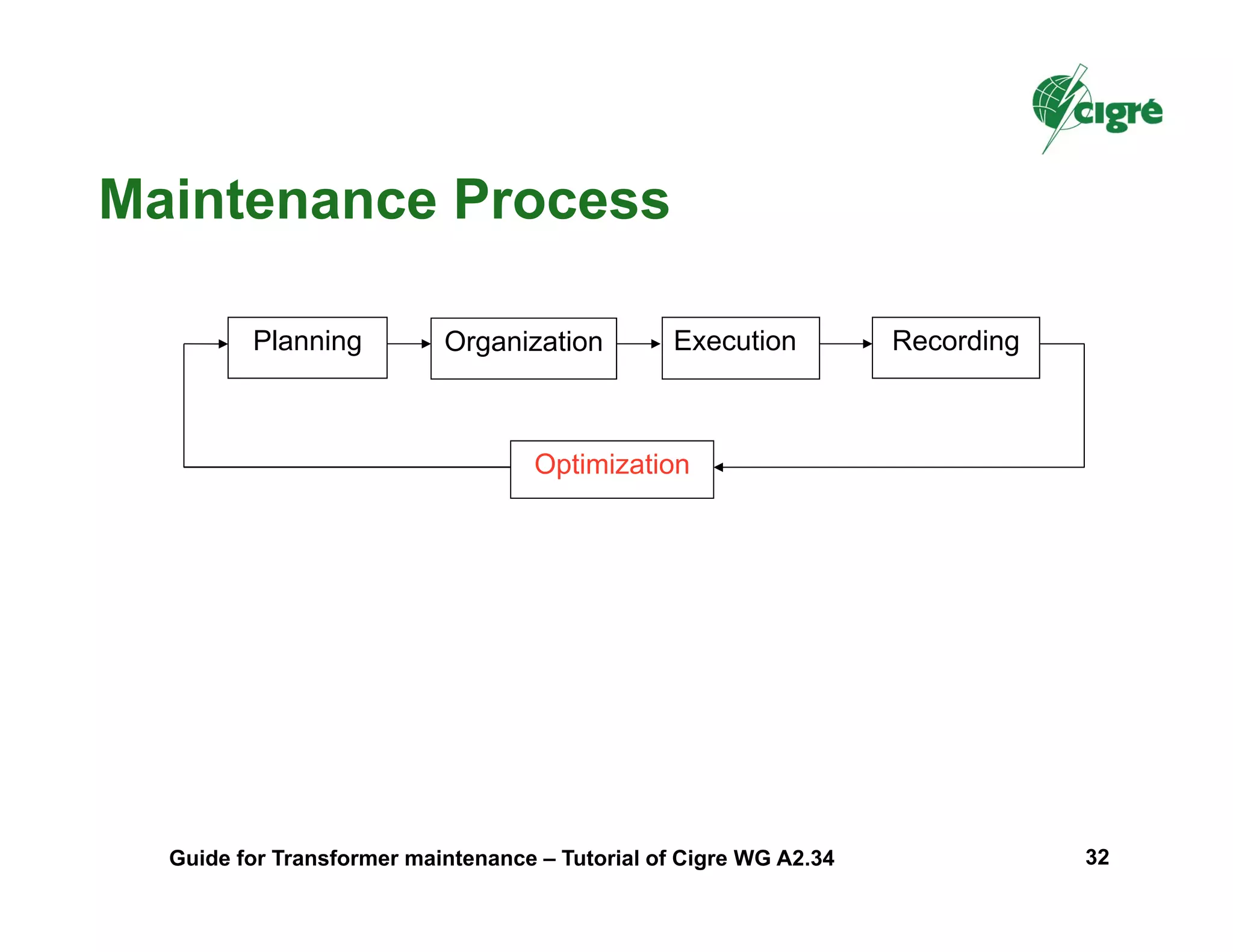


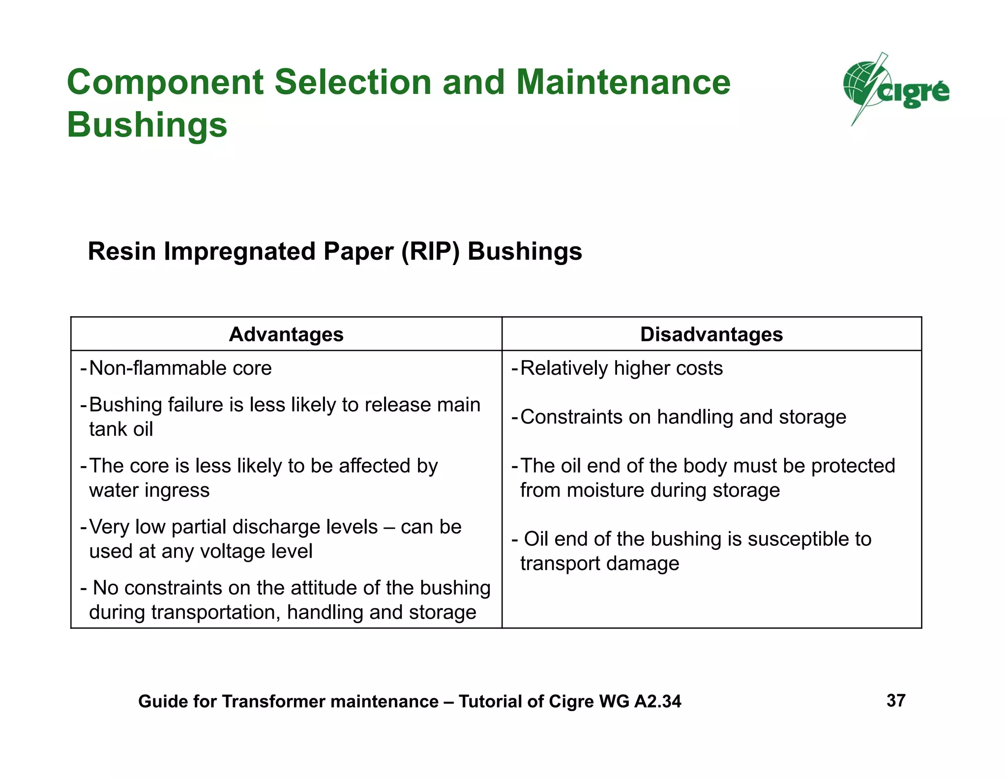
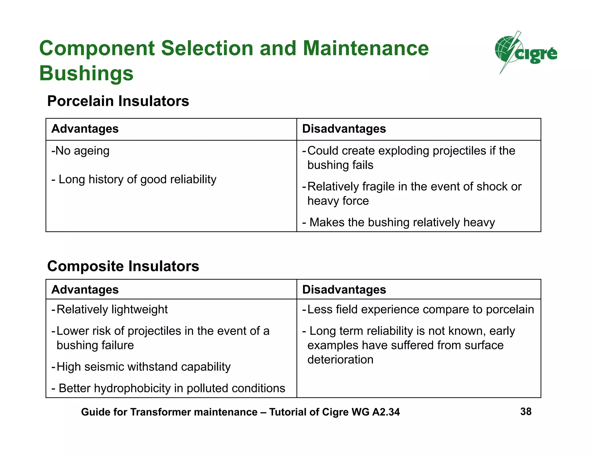


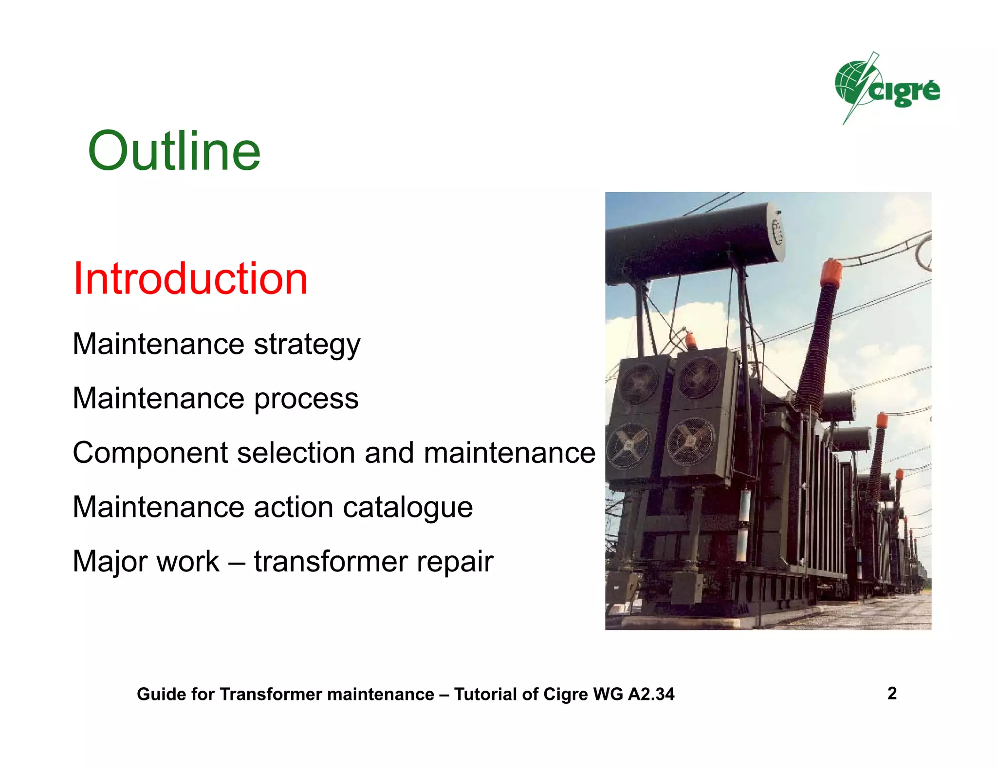
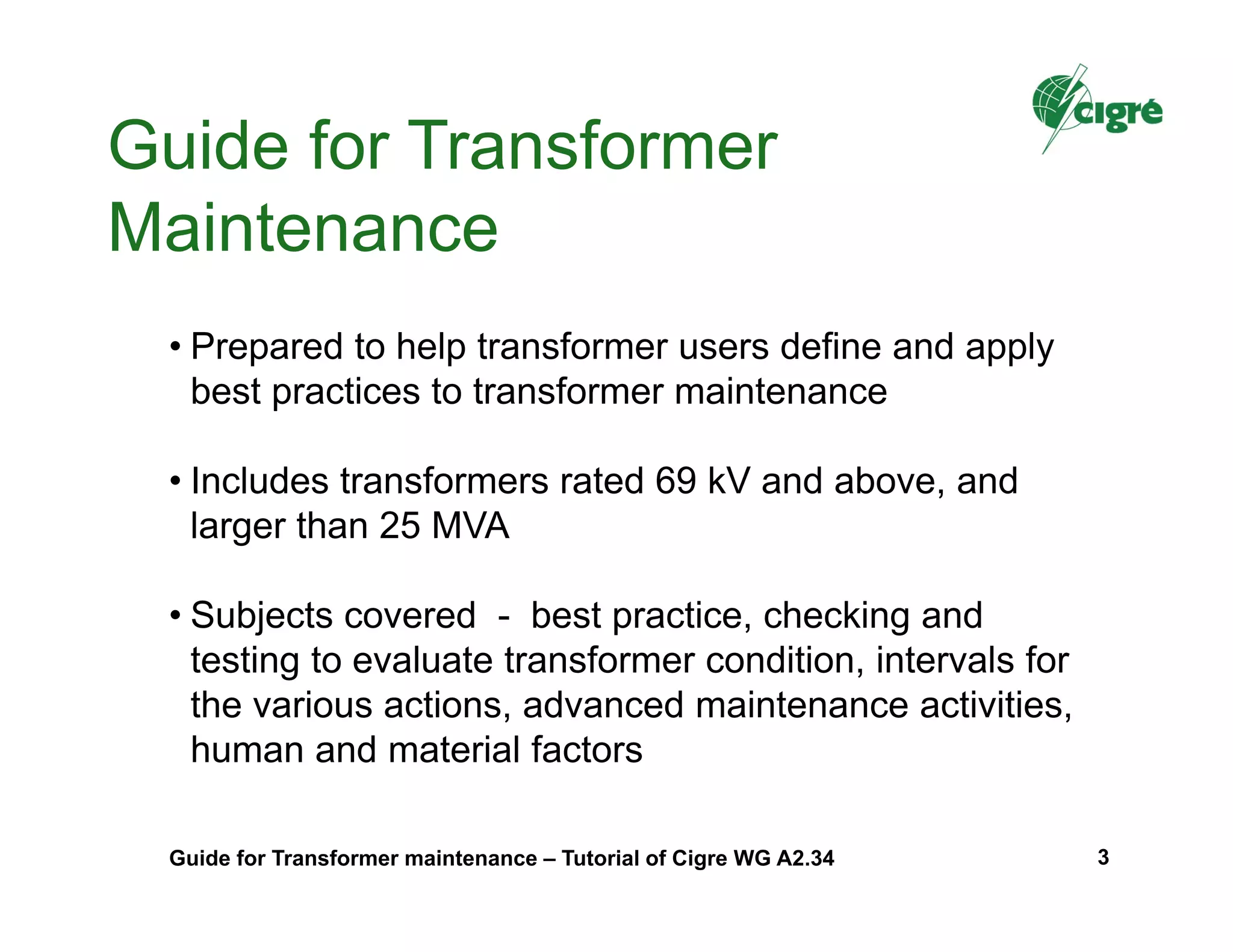
This document provides a tutorial on transformer maintenance best practices. It outlines a maintenance strategy, process, and considerations for component selection and maintenance. The maintenance strategy discusses factors that influence maintenance practices such as transformer characteristics, duty, and environment. It also presents results from a survey on current maintenance practices. The maintenance process covers planning, organization, execution, recording, and optimization. Levels of competence for maintenance tasks and safety aspects are discussed. Component selection impacts maintenance effort, and considerations for various transformer components are provided.


