Downloaded 1,727 times
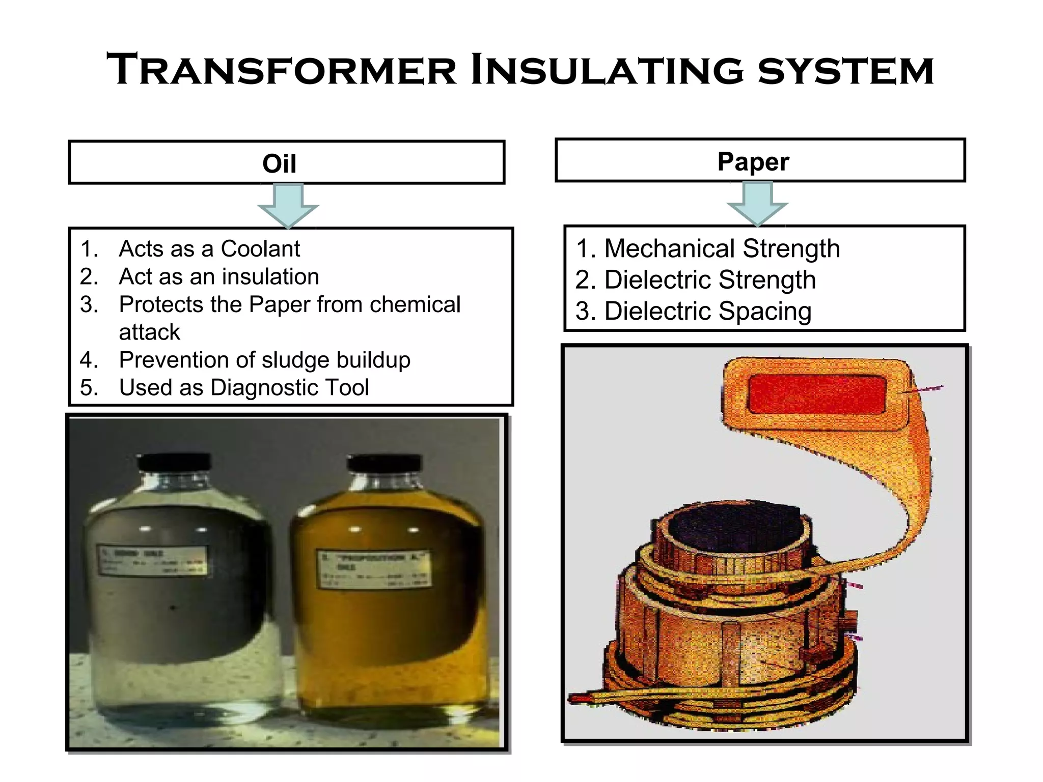
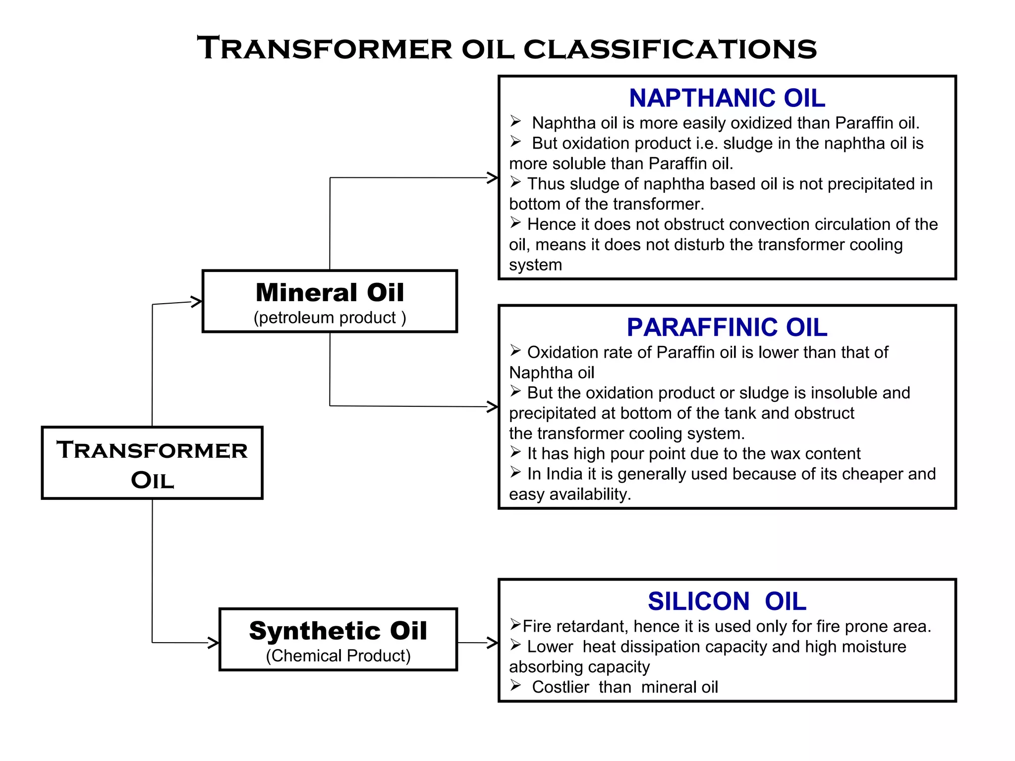
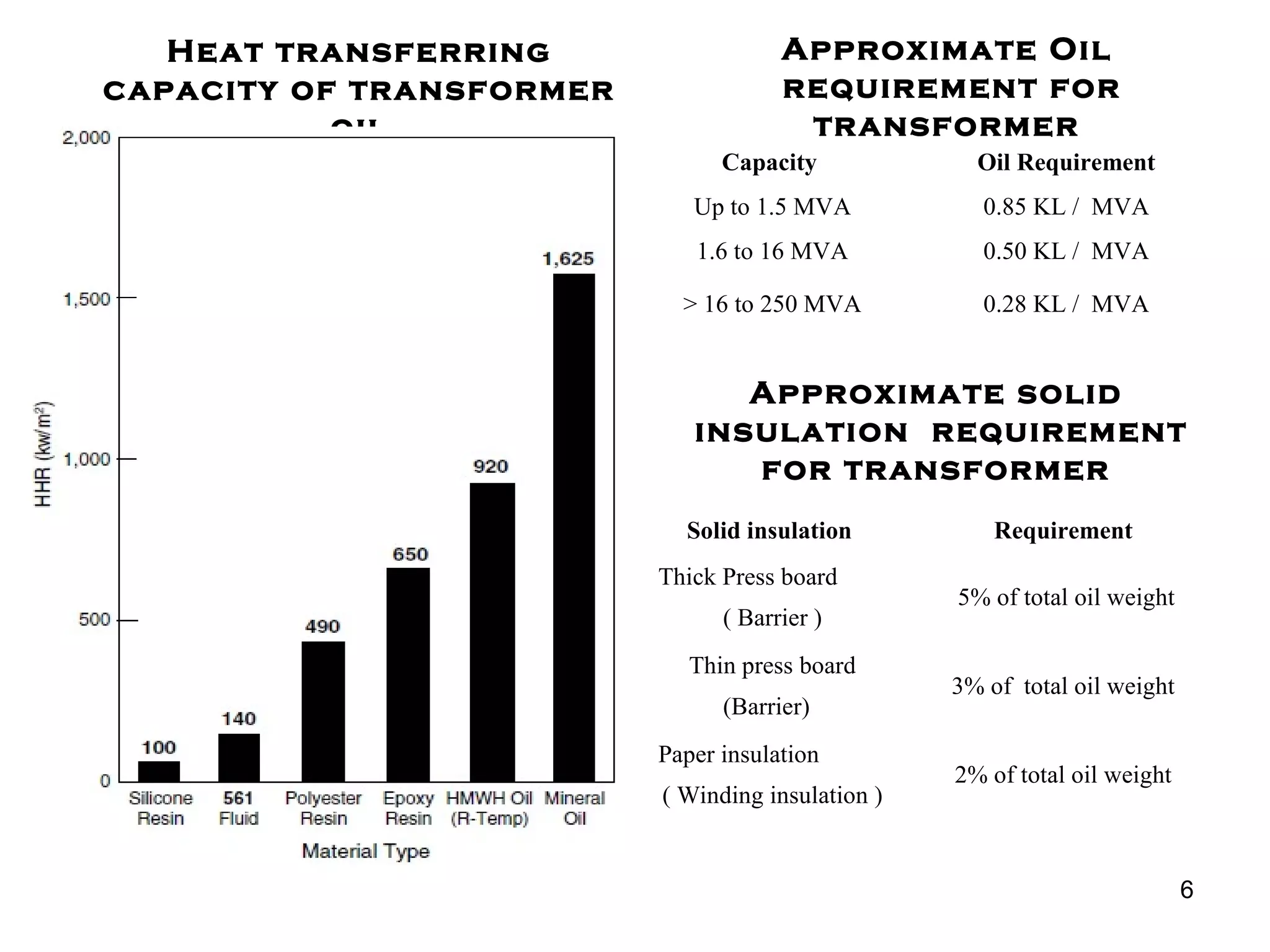
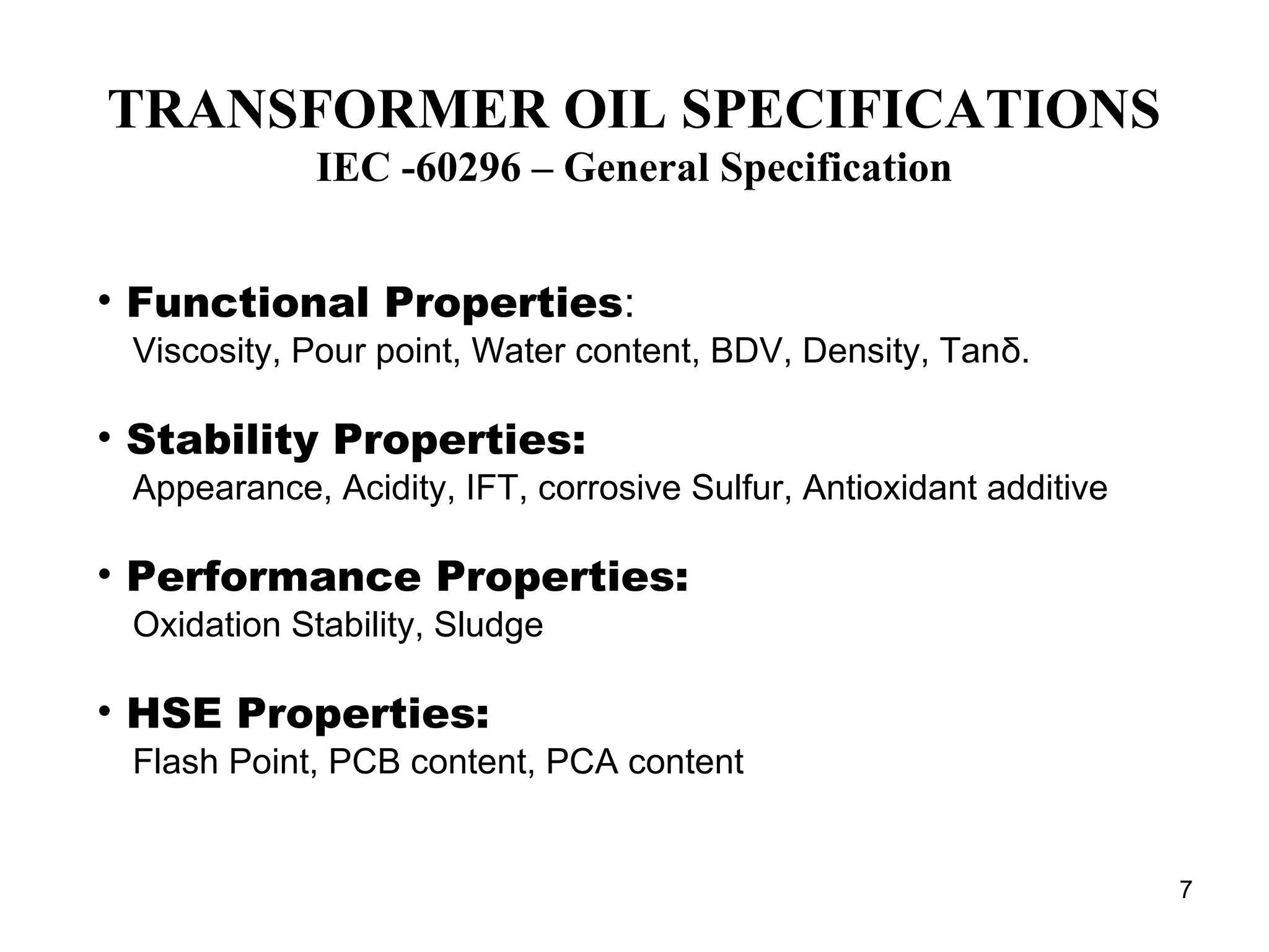
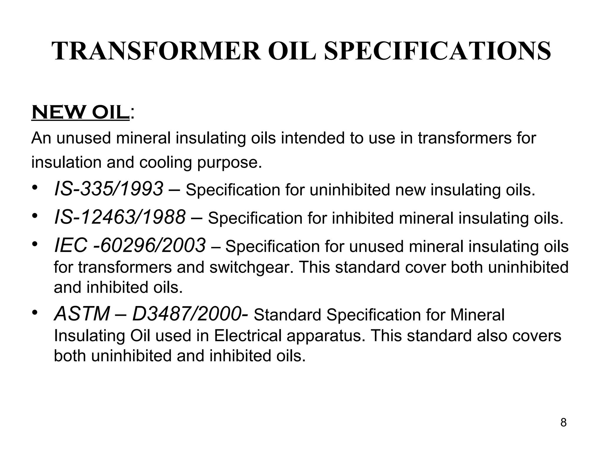
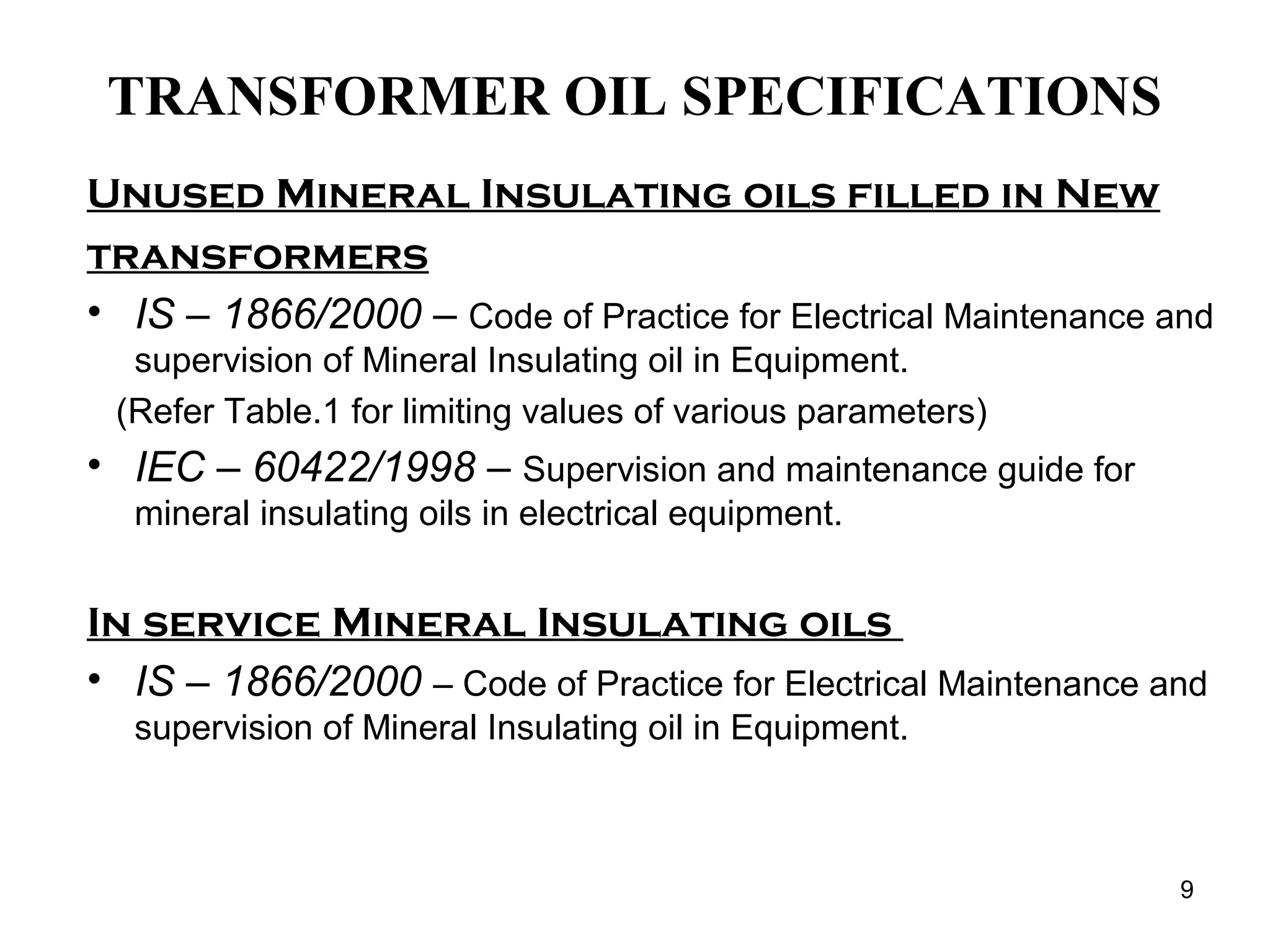
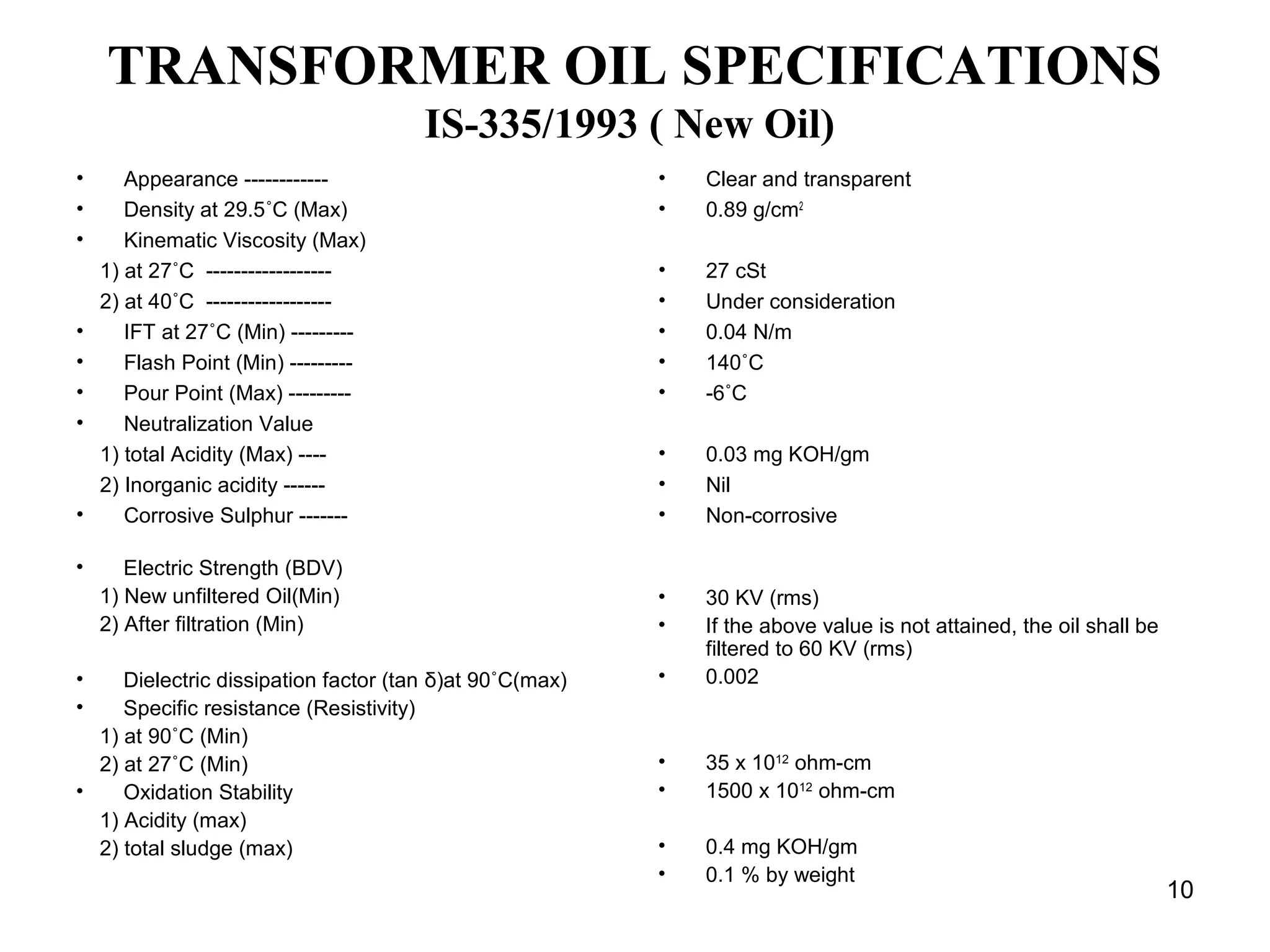
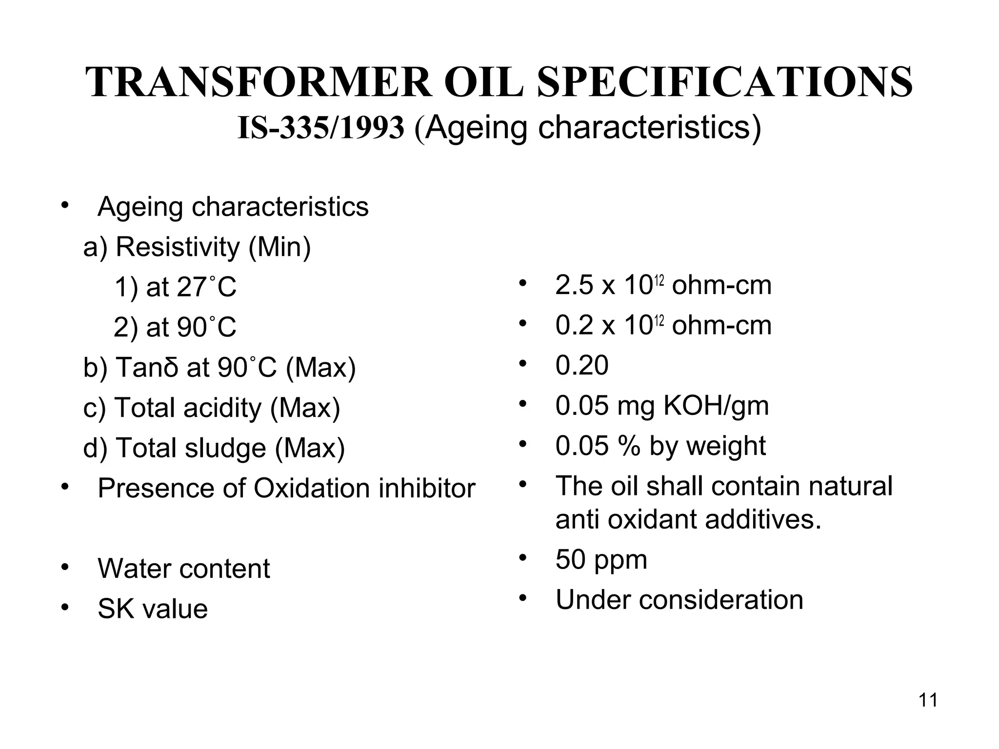
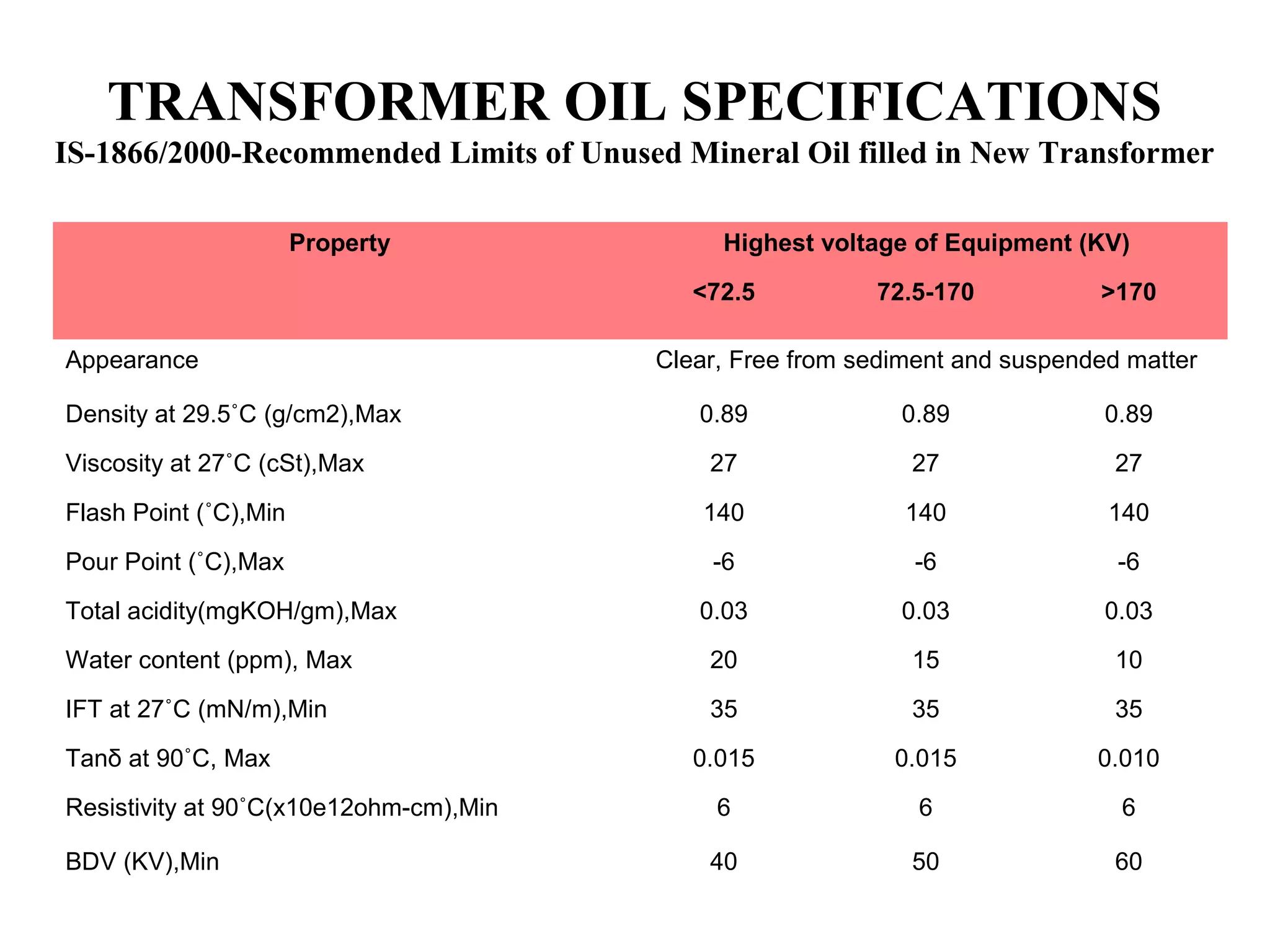
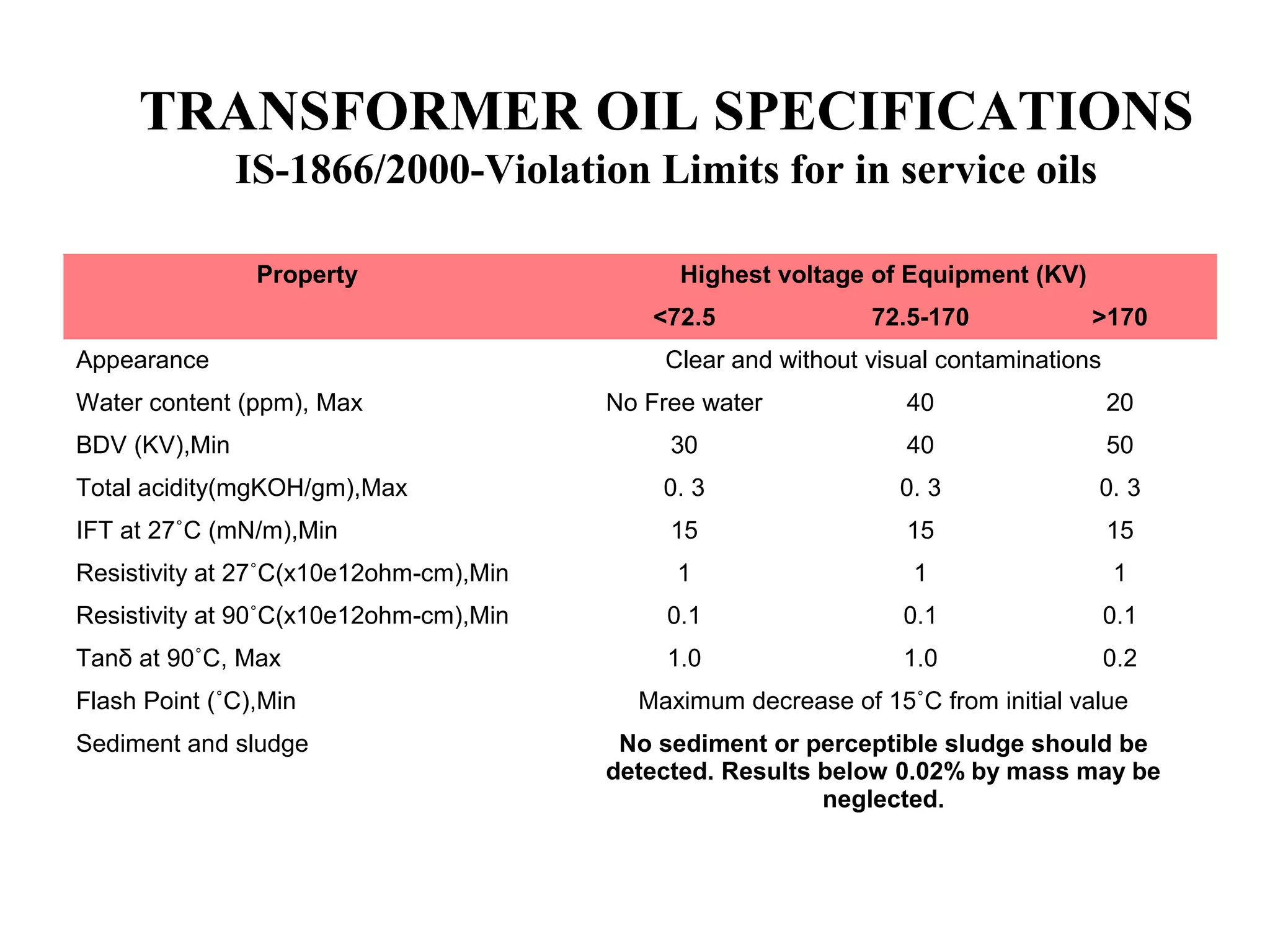
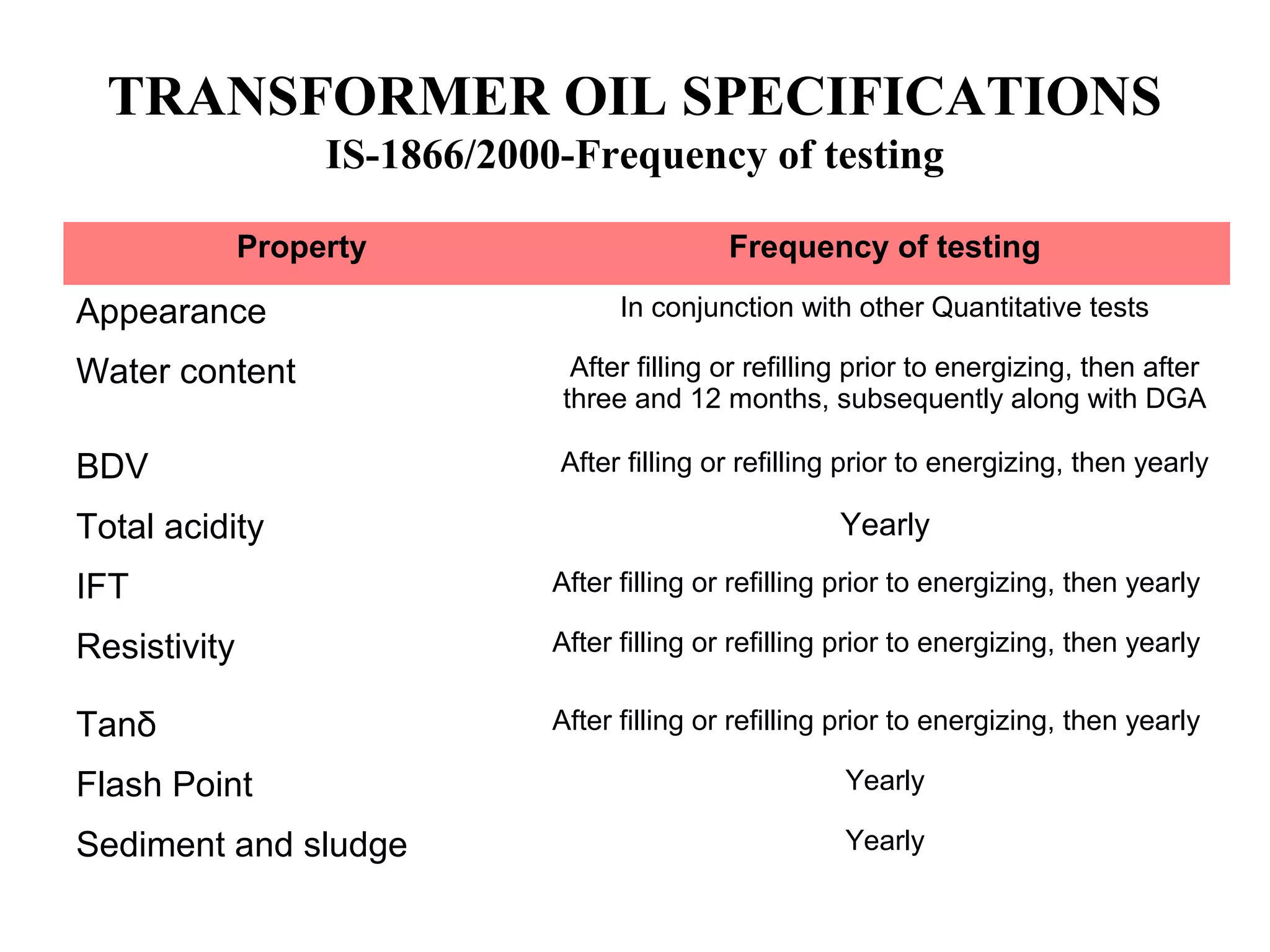
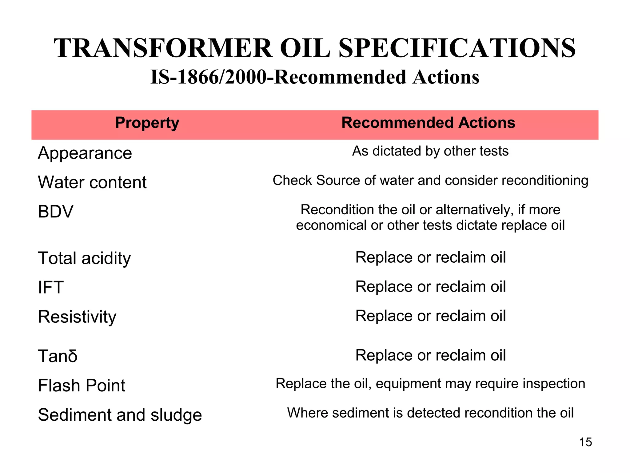
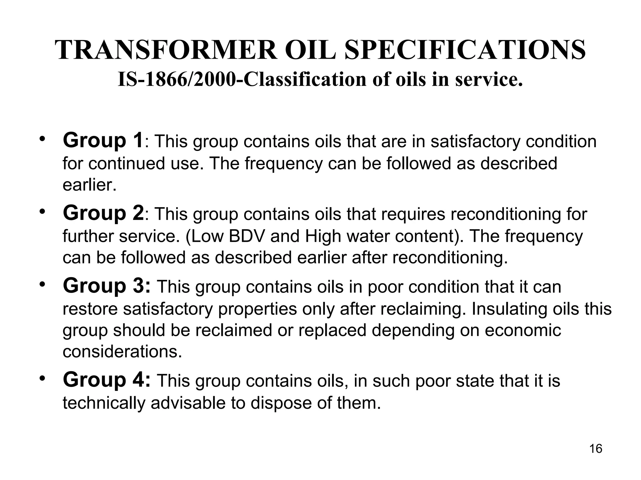
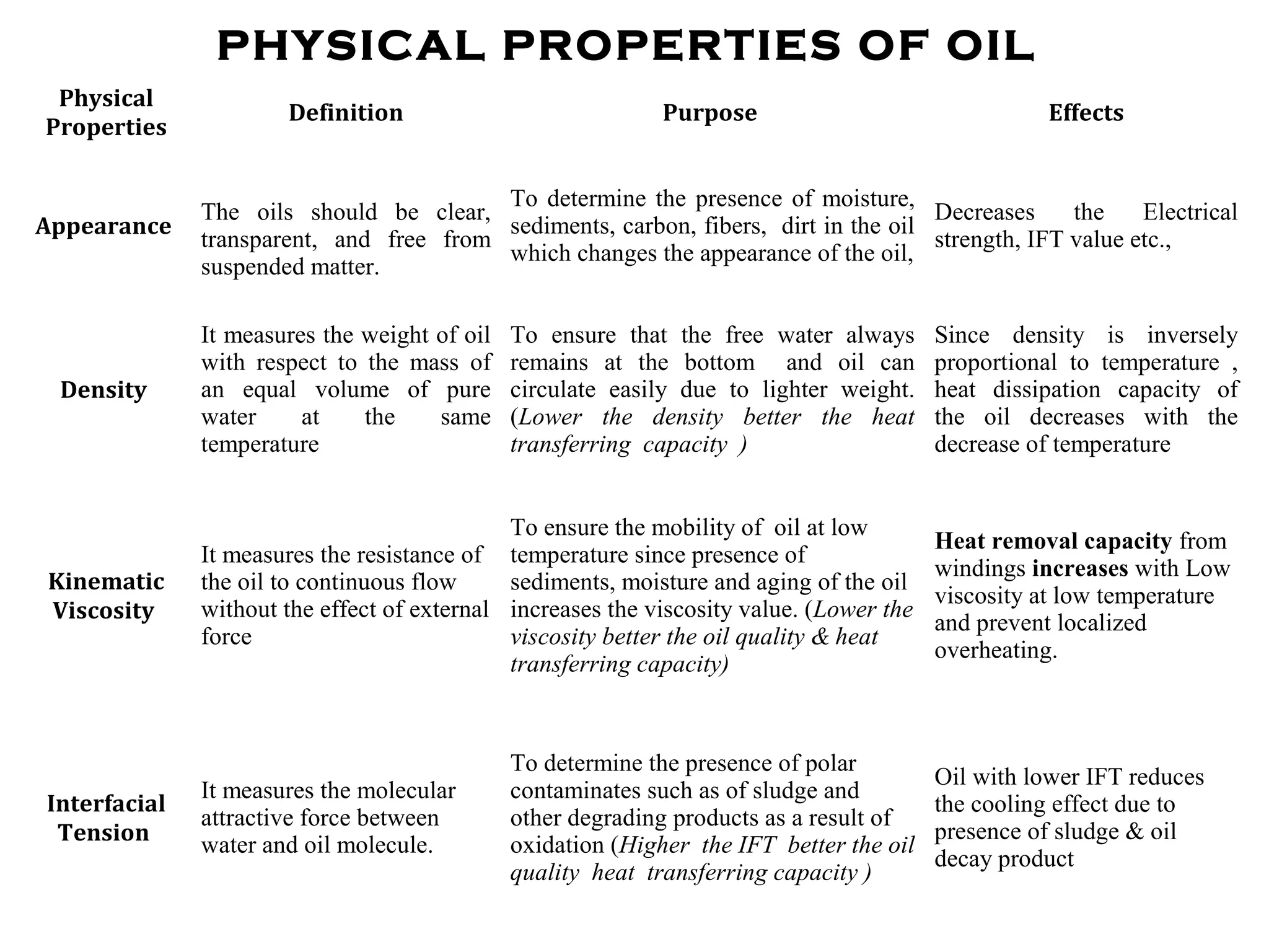
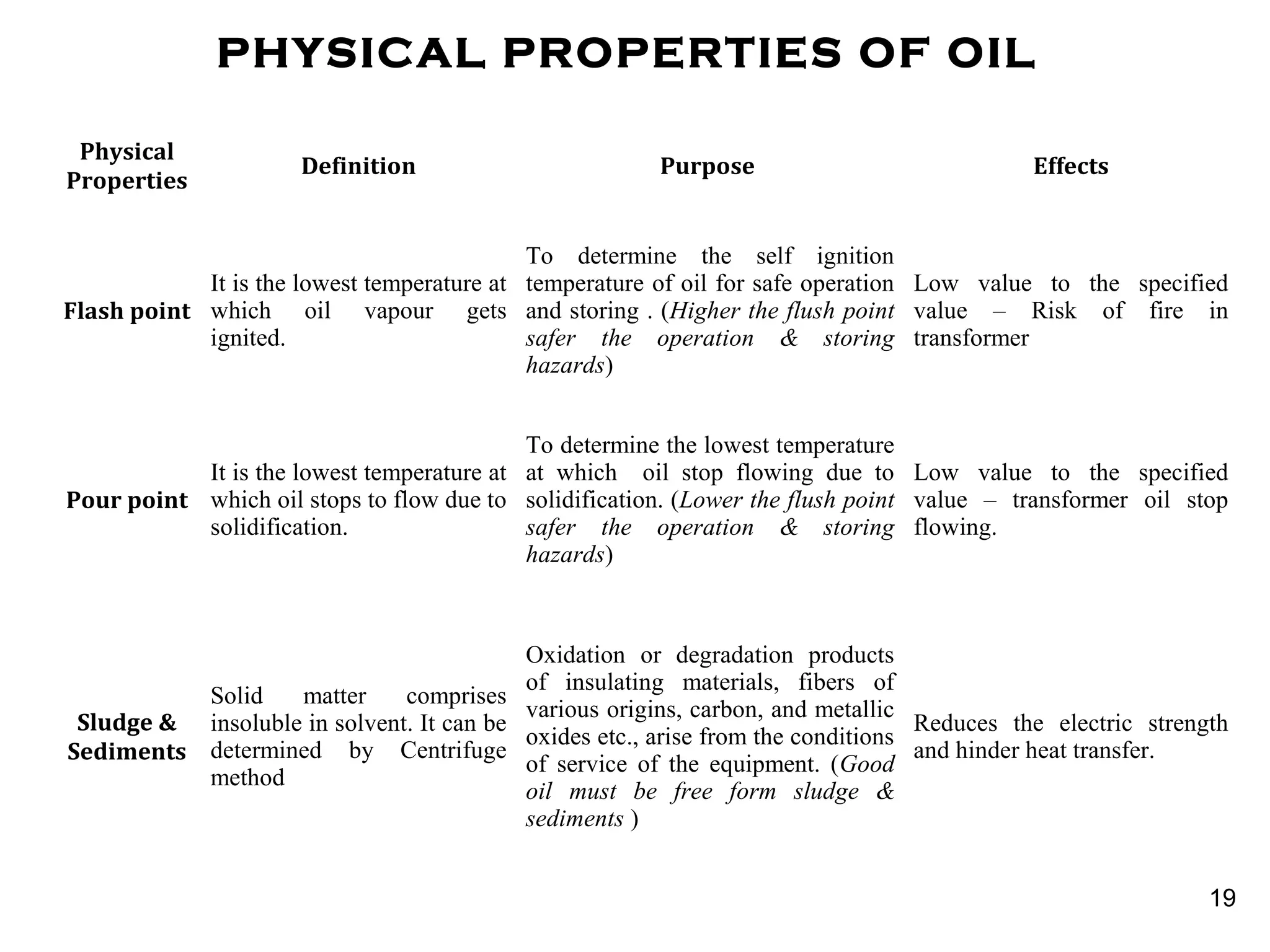
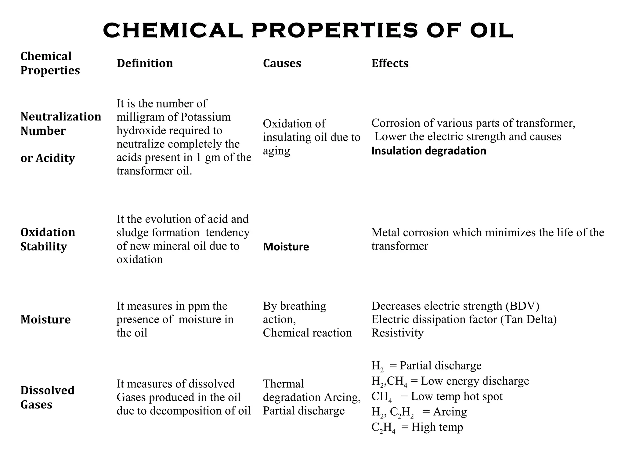
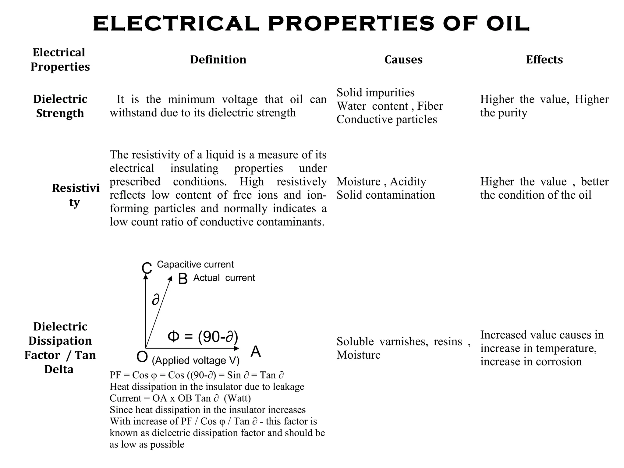
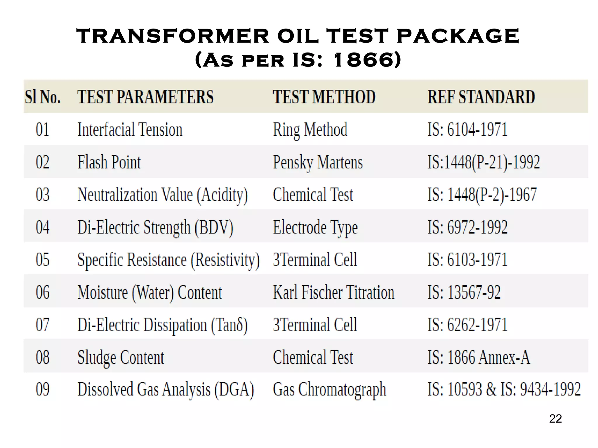
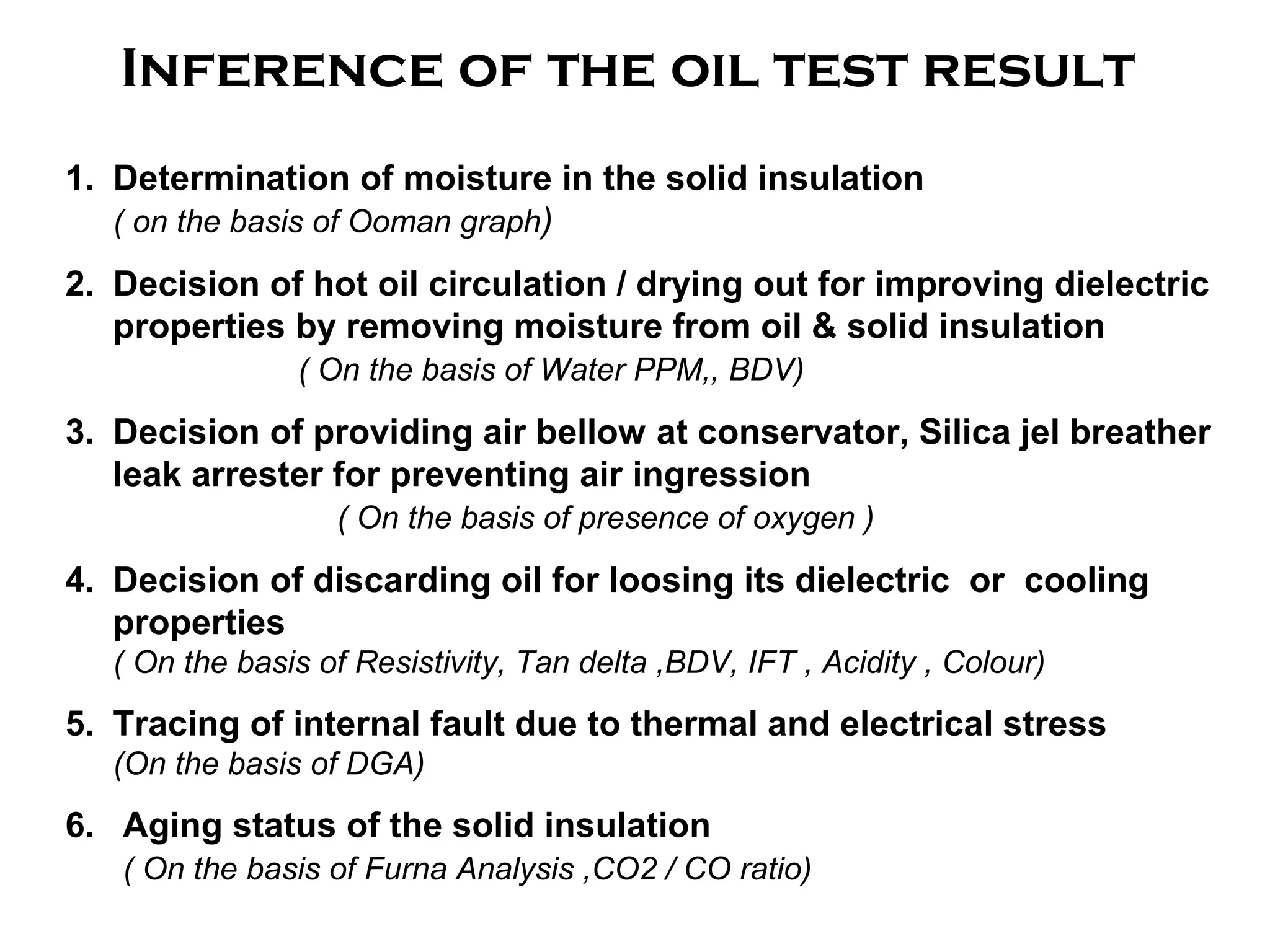
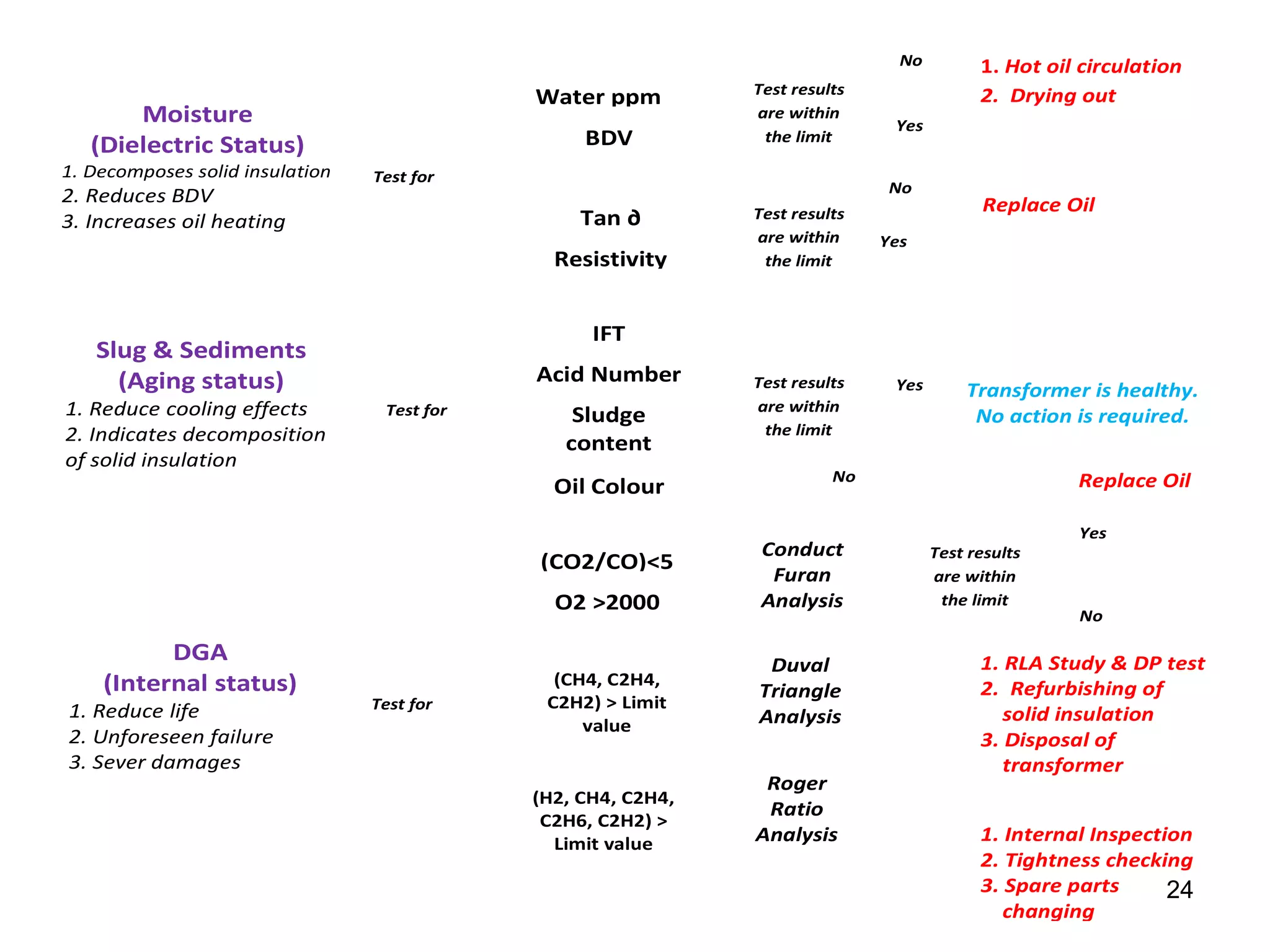
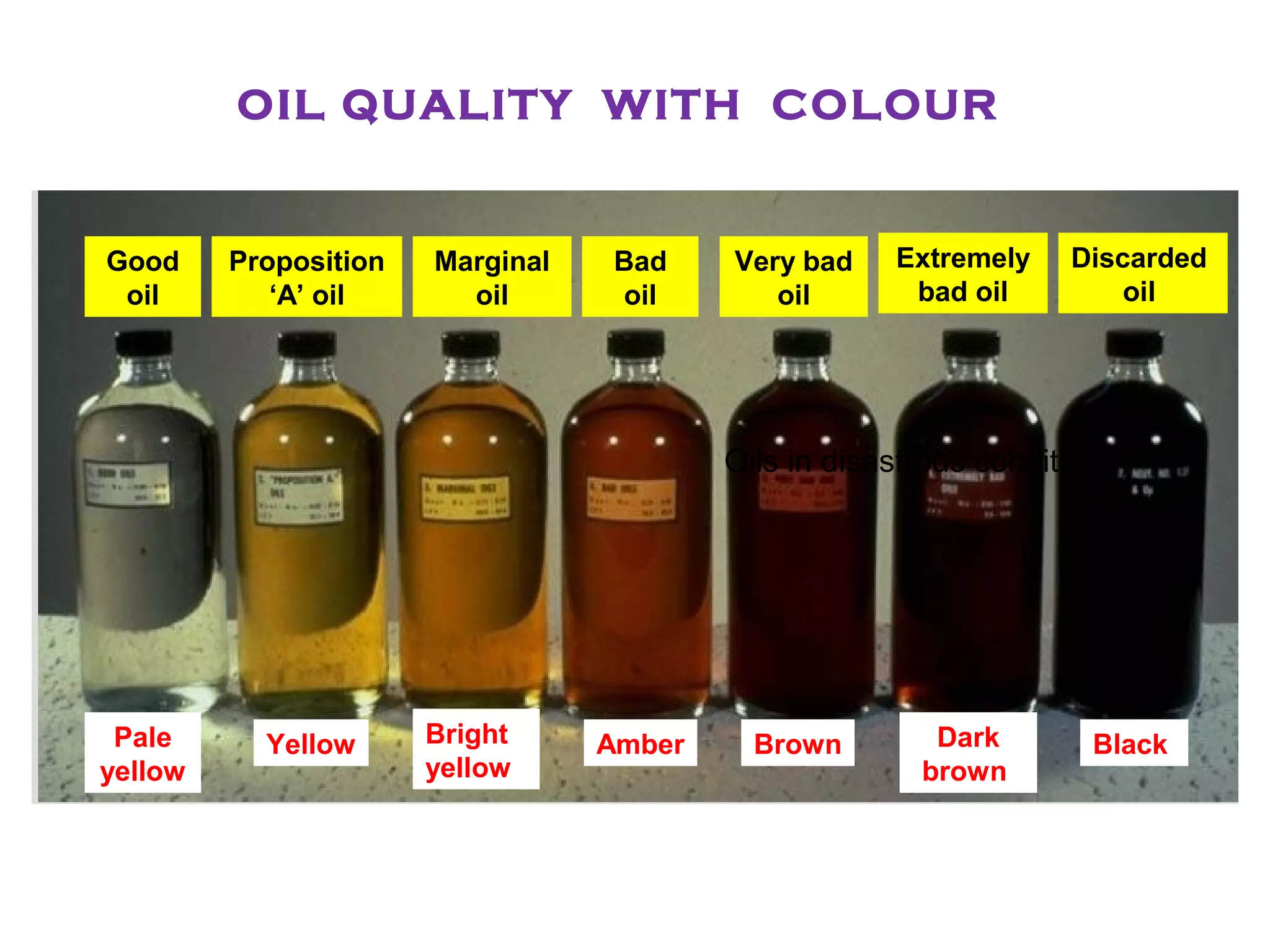


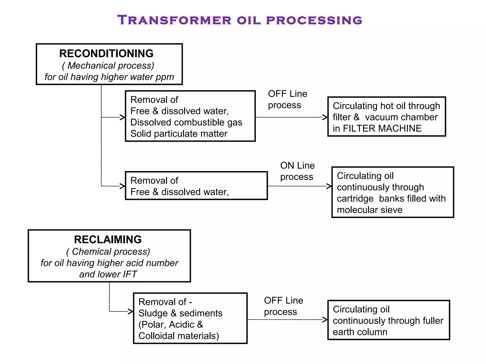
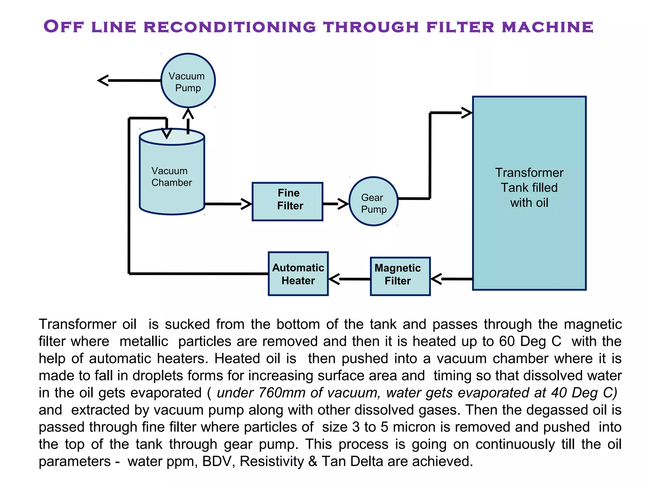
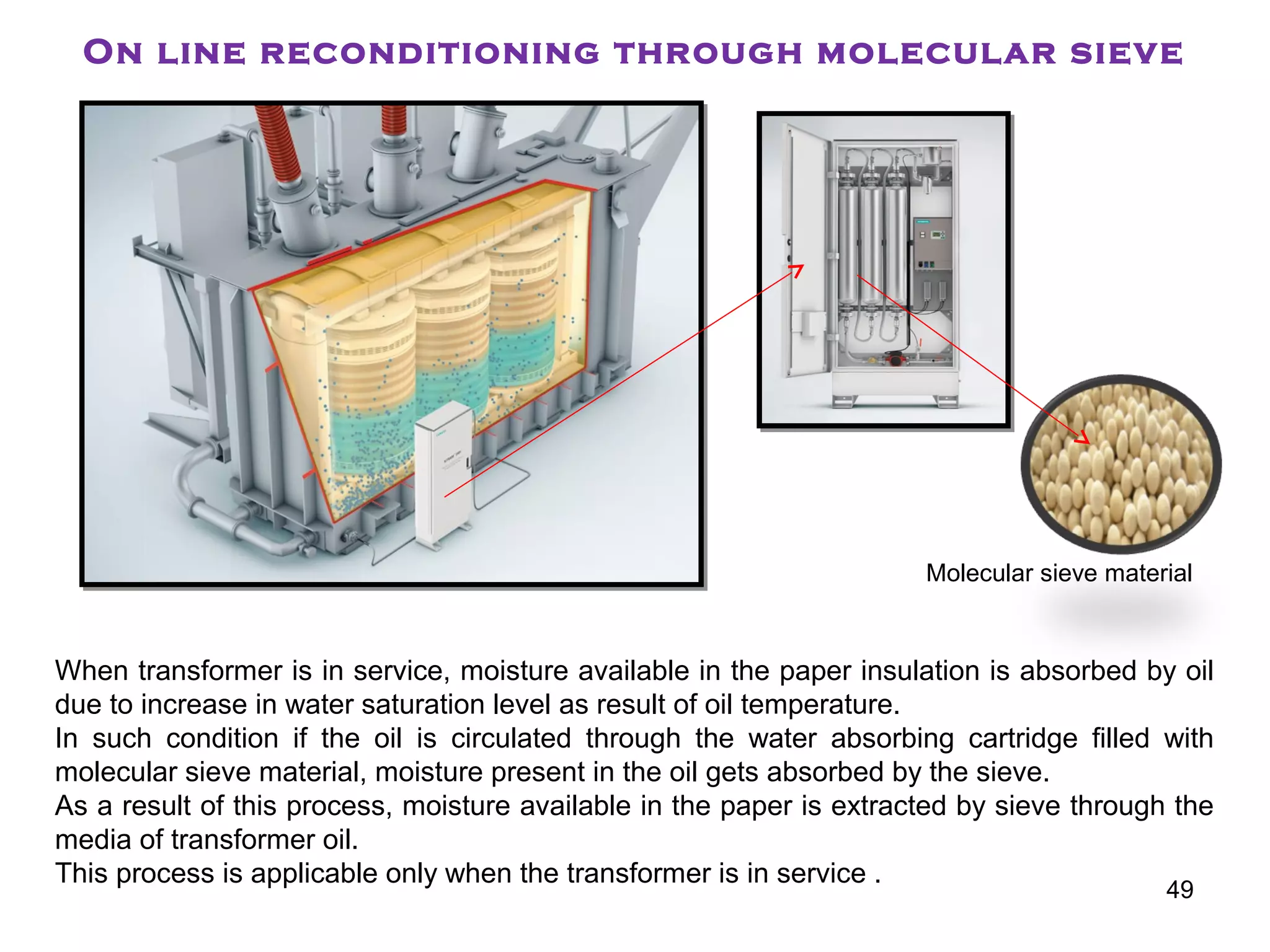
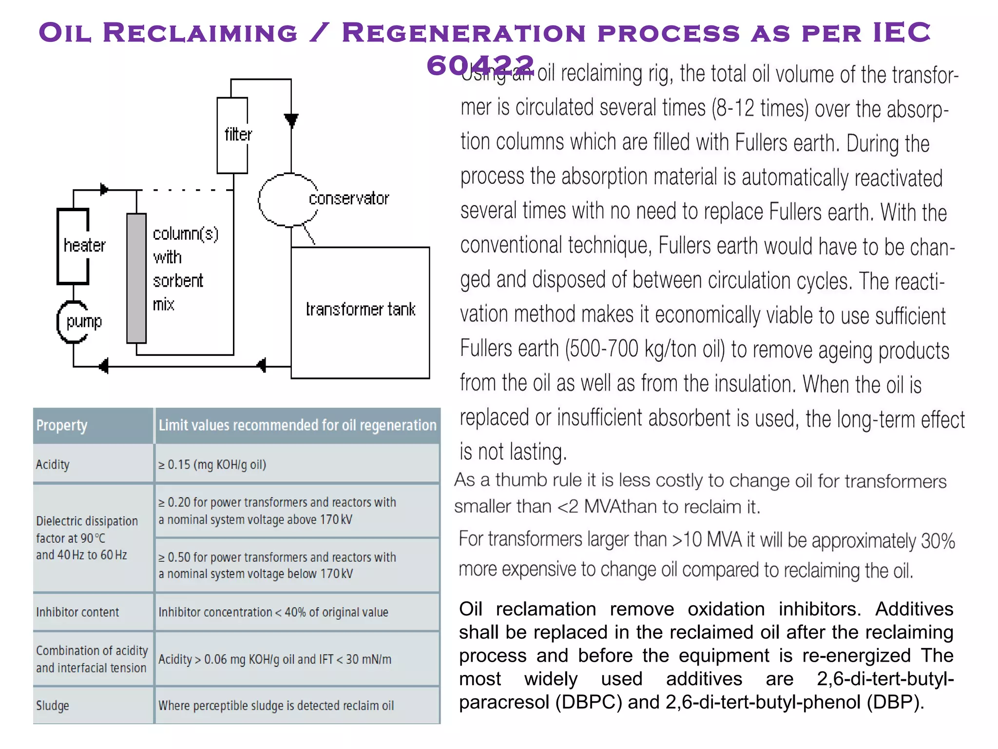
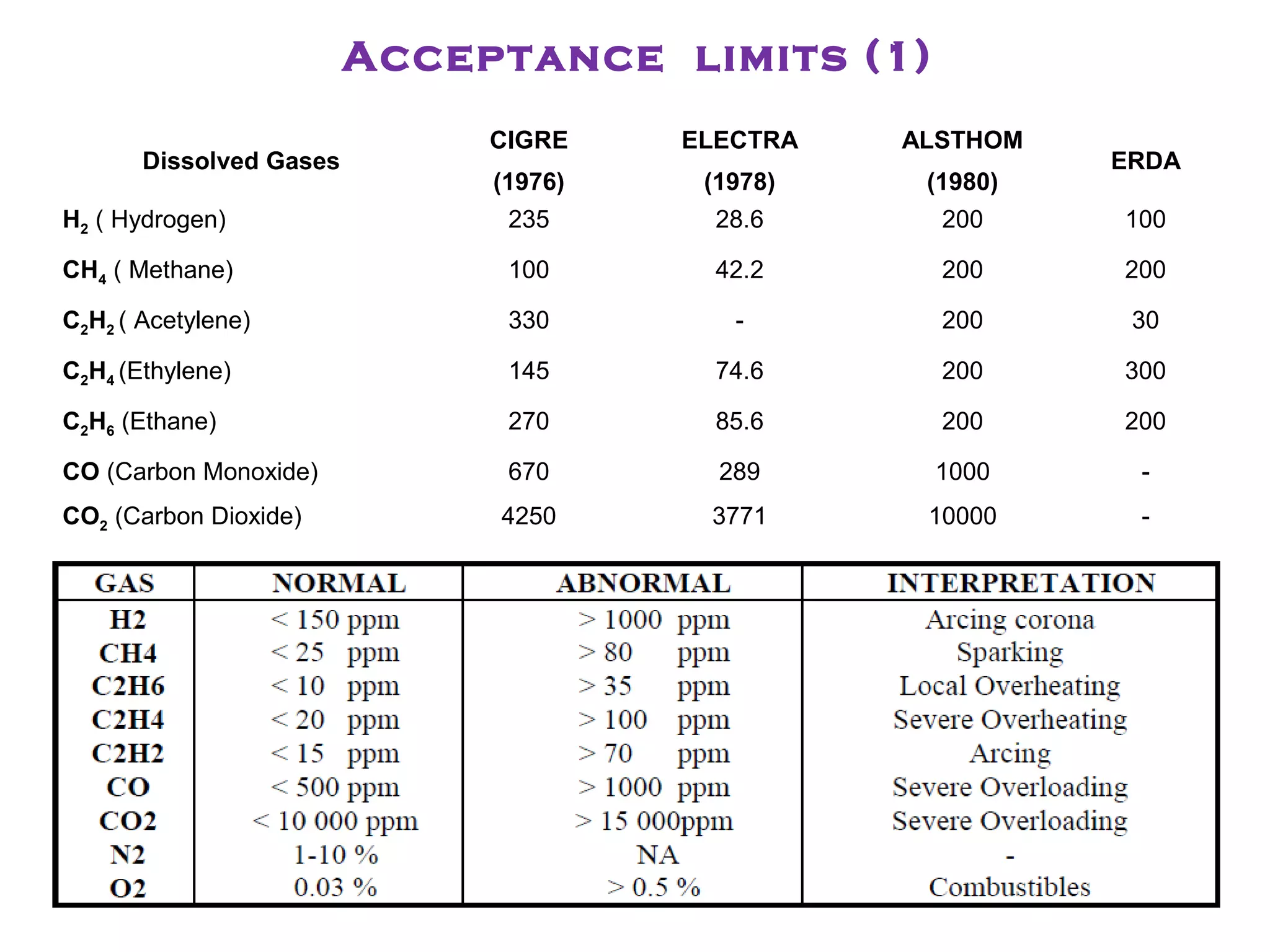


The document discusses transformer oil analysis. It describes the key components of a transformer's insulating system as the oil and paper. Transformer oil classifications include naphthenic oil, paraffinic oil, and silicon oil. The document outlines specifications for new and in-service transformer oils according to various standards. It explains the importance of various oil properties like appearance, acidity, dielectric strength, and oxidation stability and how they impact transformer performance and life.


![Vibe Coding vs. Spec-Driven Development [Free Meetup]](https://cdn.slidesharecdn.com/ss_thumbnails/vibecodingvsspecdrivendevelopment-251209105622-43f455e7-thumbnail.jpg?width=640&height=640&fit=bounds)