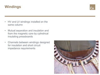
Download as PDF, PPTX
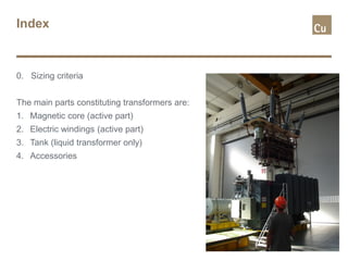
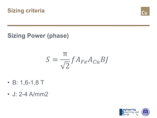


The document provides an overview of power transformer design principles, including: 1. The main components of transformers are the magnetic core, electric windings, tank (for liquid transformers), and accessories. 2. Sizing criteria includes considerations like core induction level, current density, and power rating. 3. Magnetic core design focuses on reducing losses and sound levels through choices of material, induction value, core type (single or three phase), section shape, interwoven methods, and packaging/locking.


![Chapter_3-Transformers[1]-1.pdf](https://cdn.slidesharecdn.com/ss_thumbnails/chapter3-transformers1-1-230622173423-be6efc48-thumbnail.jpg?width=640&height=640&fit=bounds)


