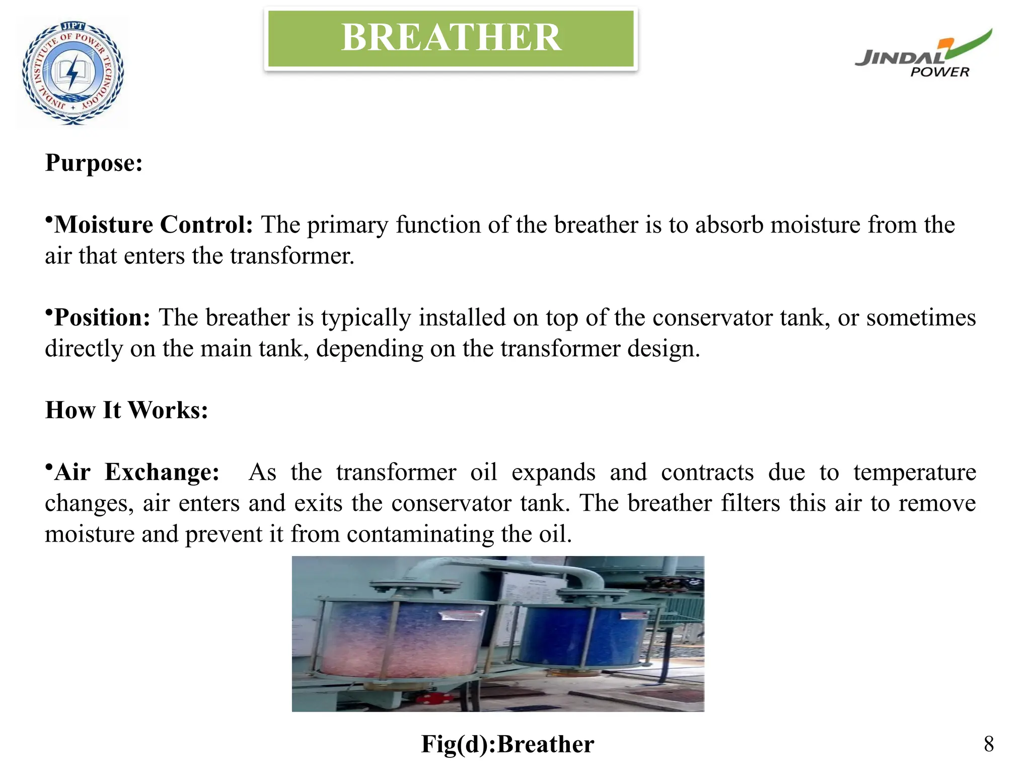
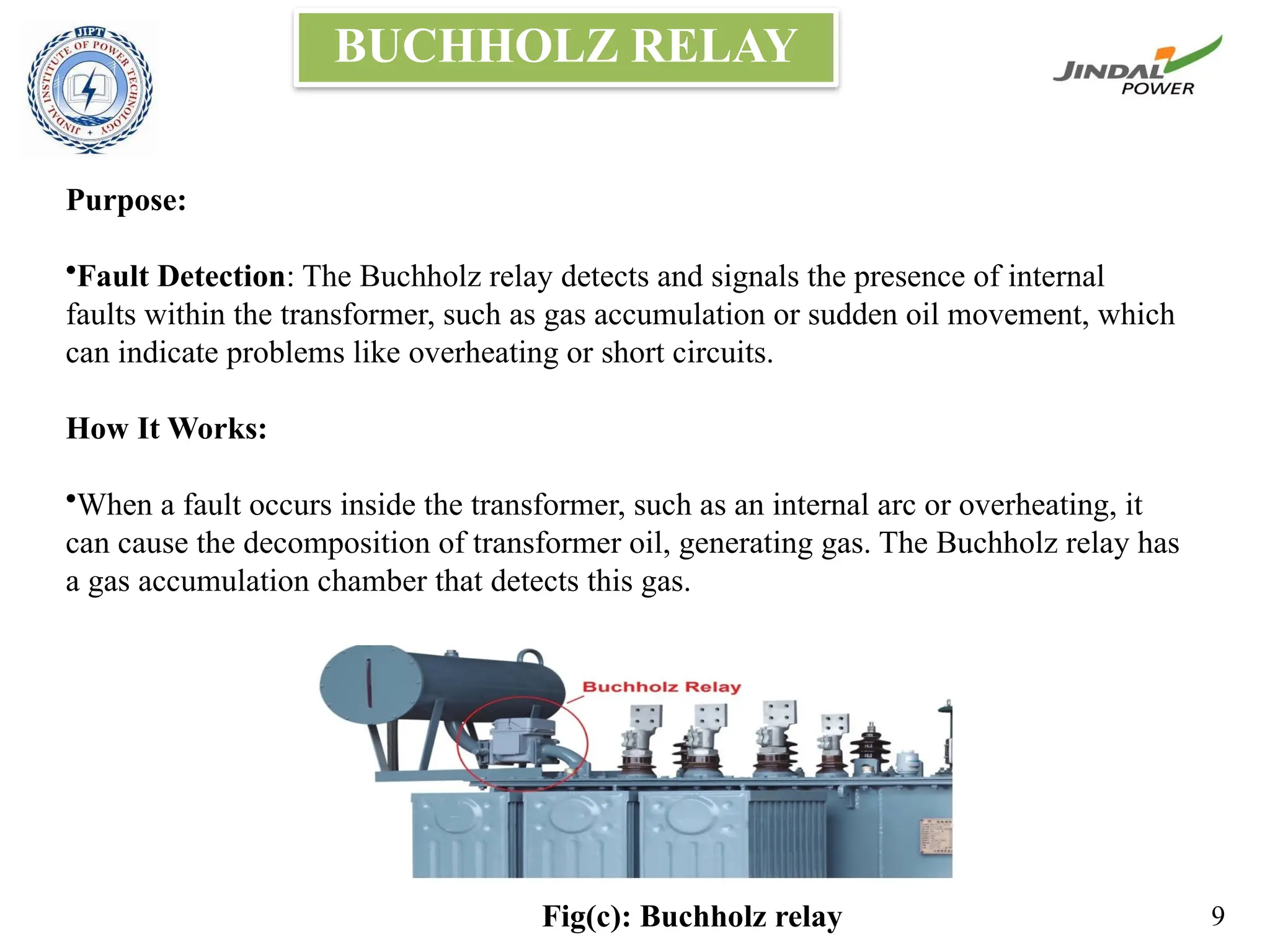
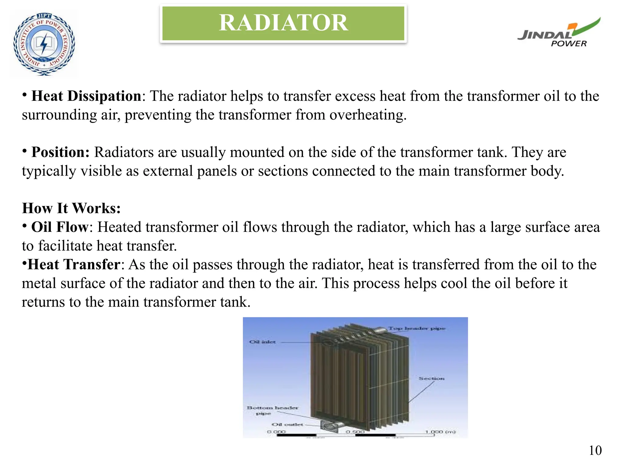
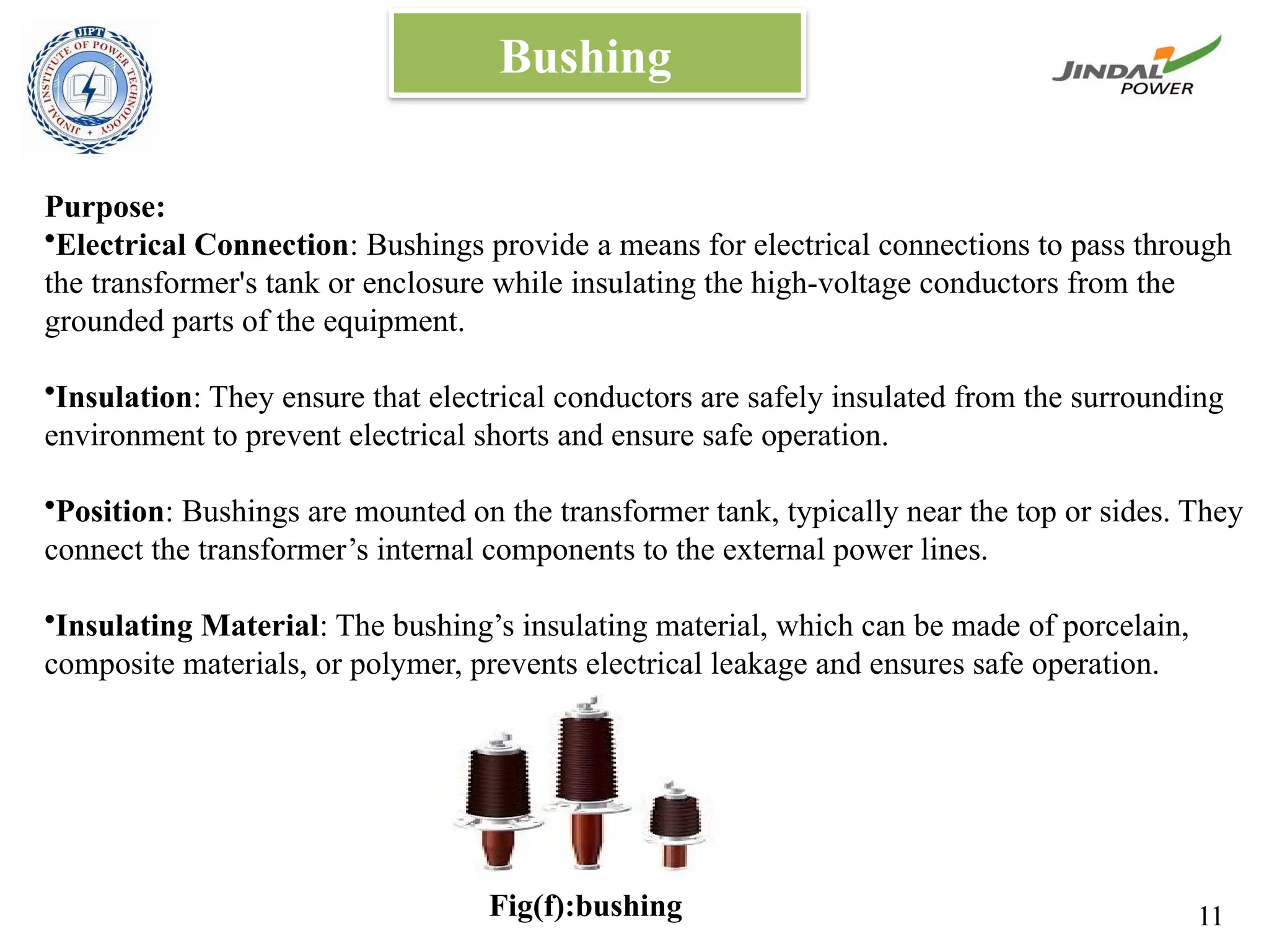
PREPARED BY:
KRISHNA RAJ GAUTAM
VIKAS SINGH KSHATRIYA
PANKAJ GOND
JINDAL INSTITUTE OF POWER
TECHNOLOGY
PRESENTATION ON: TRANSFORMERS
TABLE OF CONTENT
Parts of transformer
Advantages of transformer
Conclusion
1
PARTS OF TRANSFORMER
There are different parts of transformer :
•Laminated core
•Windings
•Insulating materials
•Transformer oil
•Conservator tank
•Buchholz Relay
•Breather
•Radiator
•Bushing
•Explosion vent
2
•Purpose: The core helps to channel the magnetic field created by the transformer’s
windings, which is essential for transferring electrical energy between the primary and
secondary coils.
•Material: The core is generally made up of Cold Rolled Grain Oriented (CRGO) steel
material.
•These are often coated with an insulating layer to prevent electrical currents from
flowing between them
•Lamination: The thin sheets are stacked together to form the core. This stacking
reduces energy losses due to eddy currents unwanted currents that can generate heat
and waste energy.
LAMINATED CORE
3
WINDINGS
• Two sets of winding are made over the transformer core and are insulated from each other.
Winding consists of several turns of copper conductors bundled together and connected in
series. Within the voltage range classification.
• High voltage winding – It is made of copper conductor. The number of turns made shall be
the multiple of the number of turns in the low-voltage winding.
• Low voltage winding – It consists of a fewer number of turns than the high voltage
winding. It is made of thick copper conductors.
Fig: windings 4
INSULATION
•Purpose:
•Electrical Safety: Prevents electrical currents from flowing where they shouldn’t, which
helps avoid short circuits and electrical faults.
•Heat Management: Helps manage and dissipate heat generated during operation to
prevent overheating.
•Types of Insulation:
•Paper Insulation: Often used in older transformers or in combination with oil. It is
impregnated with oil to enhance its insulating properties.
•Oil: In oil-filled transformers, the oil itself acts as an insulator and coolant.
5
TRANSFORMER OIL
Primary Functions:
•Insulation: Provides electrical insulation between the transformer’s internal components,
such as the windings and core, to prevent electrical shorts and ensure safe operation.
•Cooling: Acts as a coolant to dissipate the heat generated by the electrical current flowing
through the windings, helping to maintain optimal operating temperatures.
Characteristics:
•Dielectric Strength: Transformer oil needs to have high dielectric strength, which means
it must effectively insulate against electrical currents to prevent breakdown.
•Thermal Stability: The oil must remain stable and effective at high temperatures to
ensure it continues to provide cooling and insulation.
•Low Viscosity: It should flow easily to transport heat away from the core and windings.
6
CONSERVATOR TANK
Purpose:
•Oil Expansion: The conservator tank helps manage the expansion and contraction of the
transformer oil due to temperature changes. As the transformer operates, the oil heats up and
expands; when it cools down, it contracts.
Structure:
•Design: It is typically a cylindrical tank mounted above the main transformer tank. It is
connected to the main tank via a pipe.
•Location: Positioned above the main transformer tank, often on the top or side, depending
on the design of the transformer.
Fig(b): Conservator tank 7
BREATHER
Purpose:
•Moisture Control: The primary function of the breather is to absorb moisture from the
air that enters the transformer.
•Position: The breather is typically installed on top of the conservator tank, or sometimes
directly on the main tank, depending on the transformer design.
How It Works:
•Air Exchange: As the transformer oil expands and contracts due to temperature
changes, air enters and exits the conservator tank. The breather filters this air to remove
moisture and prevent it from contaminating the oil.
Fig(d):Breather 8
BUCHHOLZ RELAY
Purpose:
•Fault Detection: The Buchholz relay detects and signals the presence of internal
faults within the transformer, such as gas accumulation or sudden oil movement, which
can indicate problems like overheating or short circuits.
How It Works:
•When a fault occurs inside the transformer, such as an internal arc or overheating, it
can cause the decomposition of transformer oil, generating gas. The Buchholz relay has
a gas accumulation chamber that detects this gas.
Fig(c): Buchholz relay 9
RADIATOR
• Heat Dissipation: The radiator helps to transfer excess heat from the transformer oil to the
surrounding air, preventing the transformer from overheating.
• Position: Radiators are usually mounted on the side of the transformer tank. They are
typically visible as external panels or sections connected to the main transformer body.
How It Works:
• Oil Flow: Heated transformer oil flows through the radiator, which has a large surface area
to facilitate heat transfer.
•Heat Transfer: As the oil passes through the radiator, heat is transferred from the oil to the
metal surface of the radiator and then to the air. This process helps cool the oil before it
returns to the main transformer tank.
10
Bushing
Purpose:
•Electrical Connection: Bushings provide a means for electrical connections to pass through
the transformer's tank or enclosure while insulating the high-voltage conductors from the
grounded parts of the equipment.
•Insulation: They ensure that electrical conductors are safely insulated from the surrounding
environment to prevent electrical shorts and ensure safe operation.
•Position: Bushings are mounted on the transformer tank, typically near the top or sides. They
connect the transformer’s internal components to the external power lines.
•Insulating Material: The bushing’s insulating material, which can be made of porcelain,
composite materials, or polymer, prevents electrical leakage and ensures safe operation.
Fig(f):bushing 11
Explosion vent
•Safety Protection: The explosion vent is designed to release pressure and gases that build
up inside the transformer due to an internal fault or explosion.
•This helps prevent the transformer from sustaining serious damage or causing a more
hazardous situation.
Position: Explosion vents are typically installed on the top of the transformer tank or on
the conservator tank.
•They are placed in strategic locations to ensure that pressure is safely directed away from
critical components.
How It Works:
•Pressure Relief: In the event of an internal fault, such as an electrical fault or overheating
that leads to an explosion or rapid gas generation, the explosion vent opens automatically
to relieve excess pressure.
12
ADVANTAGES OF TRANSFORMER
•Voltage Conversion
•Reduces Energy Loss
•Electrical Isolation
•Safety
•Versatility
•Various Applications
•Reliable Operation
•Long Lifespan
•Stable Voltage Supply
•Consistent Power
•Cost-Effective
•Low Operating Costs
13
CONCLUSION
A transformer is a passive electrical device that can change the voltage in an alternating
current (AC) electric circuit.
Transformers are used to increase or decrease the operating voltage levels between circuits.
A transformer works on the principle of electromagnetic induction and mutual induction.
Four basic functions are performed in a transformer:
• Mutual induction is present between the two linked circuits.
• There is a transfer of electrical energy from one circuit to another.
• Electric power gets transferred without showing any change in the frequency.
• Electromagnetic induction transfers electrical power.
14
THANK YOU

ppt tx 3.pptx .TRANSORMERS AND ITS PARTS

  • 1.
    PREPARED BY: KRISHNA RAJGAUTAM VIKAS SINGH KSHATRIYA PANKAJ GOND JINDAL INSTITUTE OF POWER TECHNOLOGY PRESENTATION ON: TRANSFORMERS
  • 2.
    TABLE OF CONTENT Partsof transformer Advantages of transformer Conclusion 1
  • 3.
    PARTS OF TRANSFORMER Thereare different parts of transformer : •Laminated core •Windings •Insulating materials •Transformer oil •Conservator tank •Buchholz Relay •Breather •Radiator •Bushing •Explosion vent 2
  • 4.
    •Purpose: The corehelps to channel the magnetic field created by the transformer’s windings, which is essential for transferring electrical energy between the primary and secondary coils. •Material: The core is generally made up of Cold Rolled Grain Oriented (CRGO) steel material. •These are often coated with an insulating layer to prevent electrical currents from flowing between them •Lamination: The thin sheets are stacked together to form the core. This stacking reduces energy losses due to eddy currents unwanted currents that can generate heat and waste energy. LAMINATED CORE 3
  • 5.
    WINDINGS • Two setsof winding are made over the transformer core and are insulated from each other. Winding consists of several turns of copper conductors bundled together and connected in series. Within the voltage range classification. • High voltage winding – It is made of copper conductor. The number of turns made shall be the multiple of the number of turns in the low-voltage winding. • Low voltage winding – It consists of a fewer number of turns than the high voltage winding. It is made of thick copper conductors. Fig: windings 4
  • 6.
    INSULATION •Purpose: •Electrical Safety: Preventselectrical currents from flowing where they shouldn’t, which helps avoid short circuits and electrical faults. •Heat Management: Helps manage and dissipate heat generated during operation to prevent overheating. •Types of Insulation: •Paper Insulation: Often used in older transformers or in combination with oil. It is impregnated with oil to enhance its insulating properties. •Oil: In oil-filled transformers, the oil itself acts as an insulator and coolant. 5
  • 7.
    TRANSFORMER OIL Primary Functions: •Insulation:Provides electrical insulation between the transformer’s internal components, such as the windings and core, to prevent electrical shorts and ensure safe operation. •Cooling: Acts as a coolant to dissipate the heat generated by the electrical current flowing through the windings, helping to maintain optimal operating temperatures. Characteristics: •Dielectric Strength: Transformer oil needs to have high dielectric strength, which means it must effectively insulate against electrical currents to prevent breakdown. •Thermal Stability: The oil must remain stable and effective at high temperatures to ensure it continues to provide cooling and insulation. •Low Viscosity: It should flow easily to transport heat away from the core and windings. 6
  • 8.
    CONSERVATOR TANK Purpose: •Oil Expansion:The conservator tank helps manage the expansion and contraction of the transformer oil due to temperature changes. As the transformer operates, the oil heats up and expands; when it cools down, it contracts. Structure: •Design: It is typically a cylindrical tank mounted above the main transformer tank. It is connected to the main tank via a pipe. •Location: Positioned above the main transformer tank, often on the top or side, depending on the design of the transformer. Fig(b): Conservator tank 7
  • 9.
    BREATHER Purpose: •Moisture Control: Theprimary function of the breather is to absorb moisture from the air that enters the transformer. •Position: The breather is typically installed on top of the conservator tank, or sometimes directly on the main tank, depending on the transformer design. How It Works: •Air Exchange: As the transformer oil expands and contracts due to temperature changes, air enters and exits the conservator tank. The breather filters this air to remove moisture and prevent it from contaminating the oil. Fig(d):Breather 8
  • 10.
    BUCHHOLZ RELAY Purpose: •Fault Detection:The Buchholz relay detects and signals the presence of internal faults within the transformer, such as gas accumulation or sudden oil movement, which can indicate problems like overheating or short circuits. How It Works: •When a fault occurs inside the transformer, such as an internal arc or overheating, it can cause the decomposition of transformer oil, generating gas. The Buchholz relay has a gas accumulation chamber that detects this gas. Fig(c): Buchholz relay 9
  • 11.
    RADIATOR • Heat Dissipation:The radiator helps to transfer excess heat from the transformer oil to the surrounding air, preventing the transformer from overheating. • Position: Radiators are usually mounted on the side of the transformer tank. They are typically visible as external panels or sections connected to the main transformer body. How It Works: • Oil Flow: Heated transformer oil flows through the radiator, which has a large surface area to facilitate heat transfer. •Heat Transfer: As the oil passes through the radiator, heat is transferred from the oil to the metal surface of the radiator and then to the air. This process helps cool the oil before it returns to the main transformer tank. 10
  • 12.
    Bushing Purpose: •Electrical Connection: Bushingsprovide a means for electrical connections to pass through the transformer's tank or enclosure while insulating the high-voltage conductors from the grounded parts of the equipment. •Insulation: They ensure that electrical conductors are safely insulated from the surrounding environment to prevent electrical shorts and ensure safe operation. •Position: Bushings are mounted on the transformer tank, typically near the top or sides. They connect the transformer’s internal components to the external power lines. •Insulating Material: The bushing’s insulating material, which can be made of porcelain, composite materials, or polymer, prevents electrical leakage and ensures safe operation. Fig(f):bushing 11
  • 13.
    Explosion vent •Safety Protection:The explosion vent is designed to release pressure and gases that build up inside the transformer due to an internal fault or explosion. •This helps prevent the transformer from sustaining serious damage or causing a more hazardous situation. Position: Explosion vents are typically installed on the top of the transformer tank or on the conservator tank. •They are placed in strategic locations to ensure that pressure is safely directed away from critical components. How It Works: •Pressure Relief: In the event of an internal fault, such as an electrical fault or overheating that leads to an explosion or rapid gas generation, the explosion vent opens automatically to relieve excess pressure. 12
  • 14.
    ADVANTAGES OF TRANSFORMER •VoltageConversion •Reduces Energy Loss •Electrical Isolation •Safety •Versatility •Various Applications •Reliable Operation •Long Lifespan •Stable Voltage Supply •Consistent Power •Cost-Effective •Low Operating Costs 13
  • 15.
    CONCLUSION A transformer isa passive electrical device that can change the voltage in an alternating current (AC) electric circuit. Transformers are used to increase or decrease the operating voltage levels between circuits. A transformer works on the principle of electromagnetic induction and mutual induction. Four basic functions are performed in a transformer: • Mutual induction is present between the two linked circuits. • There is a transfer of electrical energy from one circuit to another. • Electric power gets transferred without showing any change in the frequency. • Electromagnetic induction transfers electrical power. 14
  • 16.