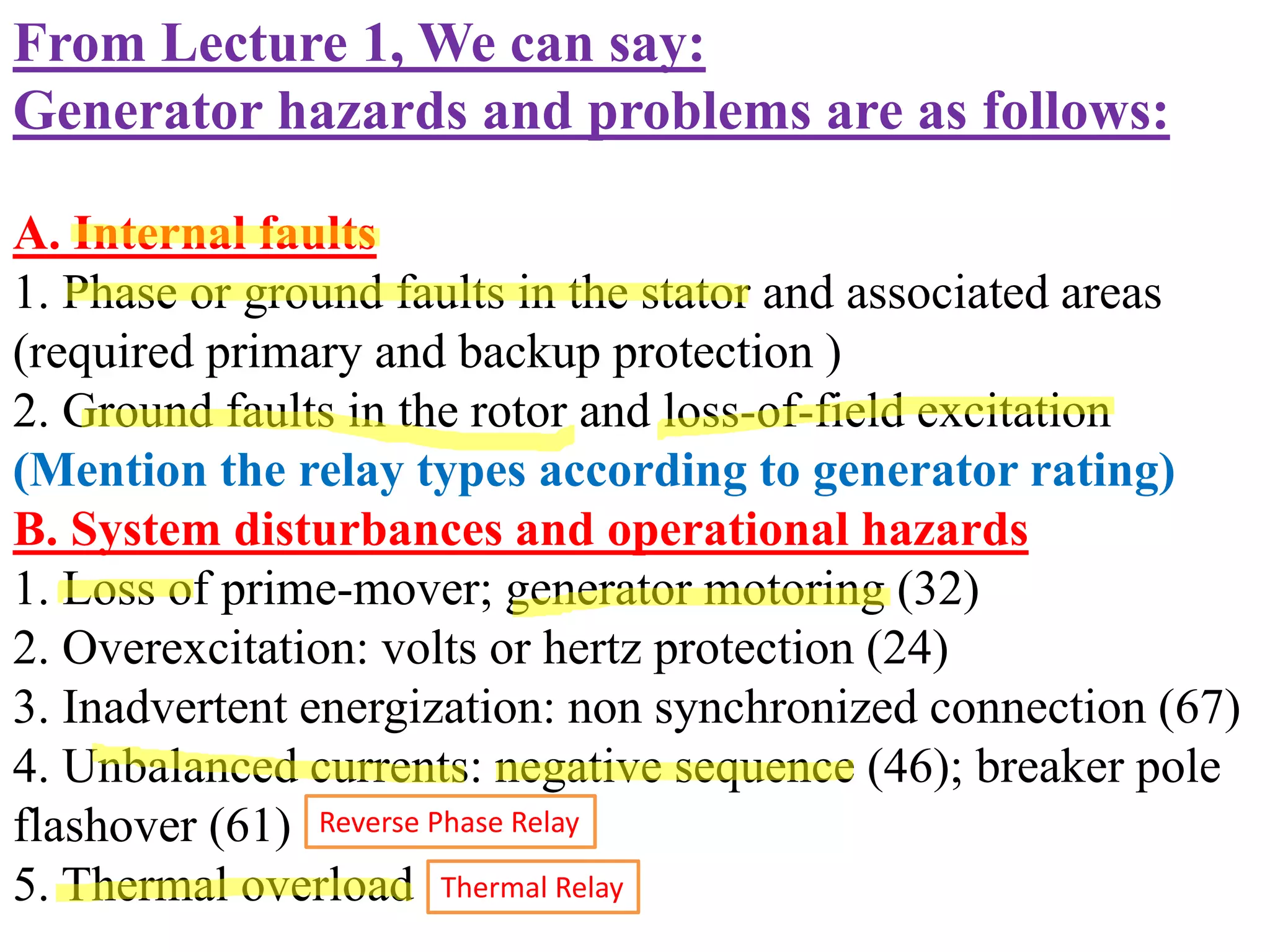
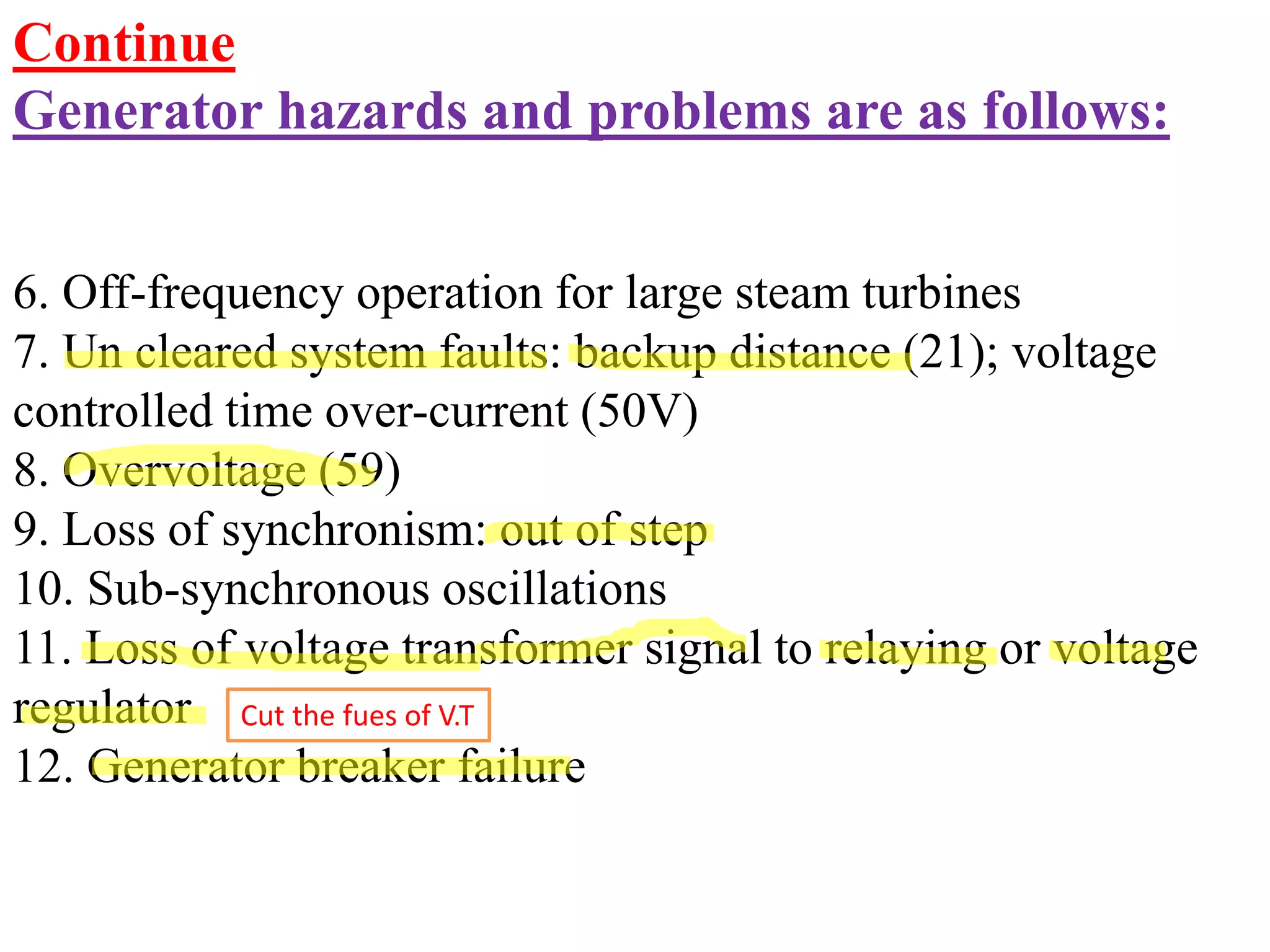
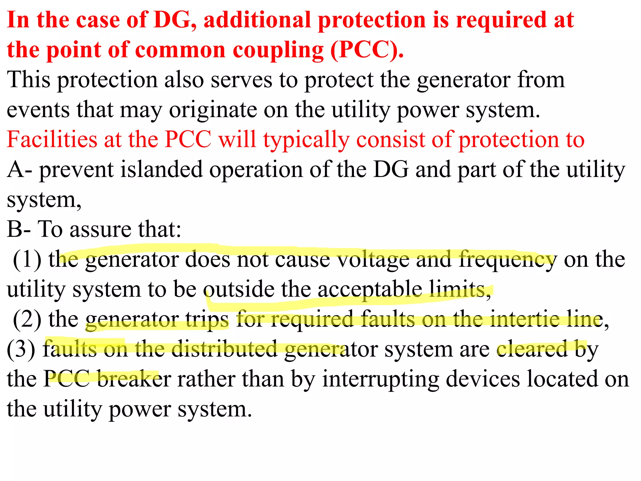
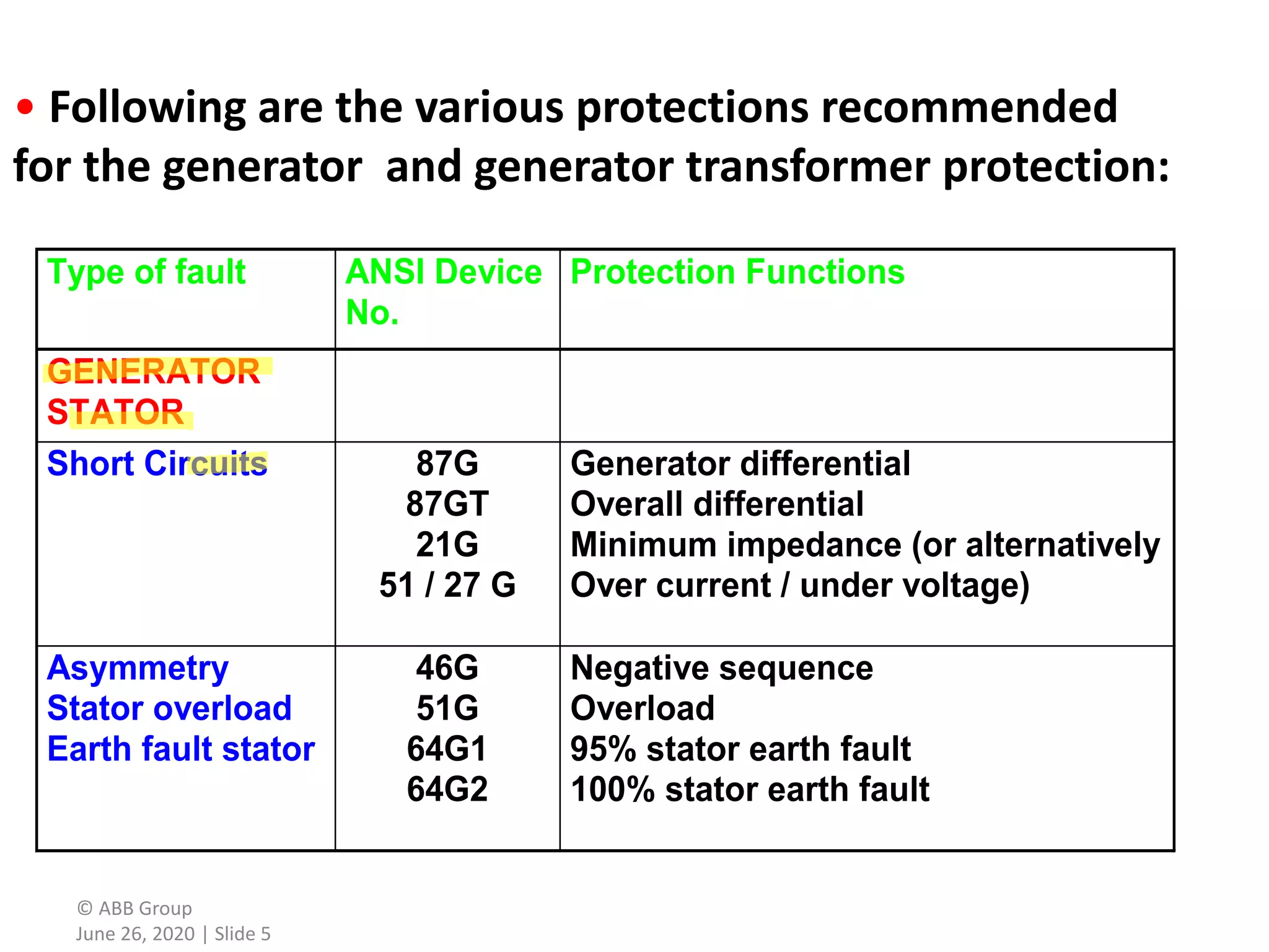
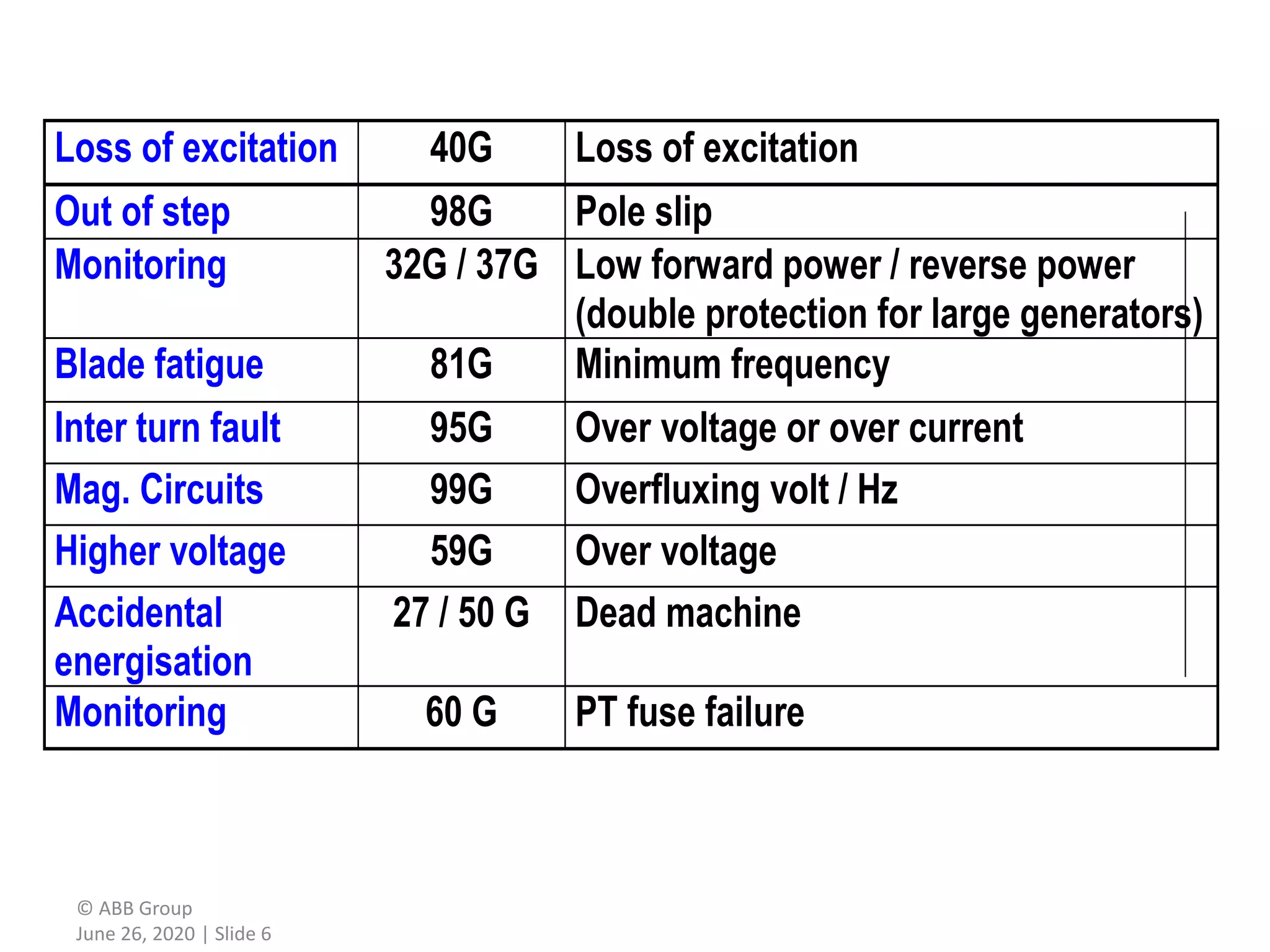
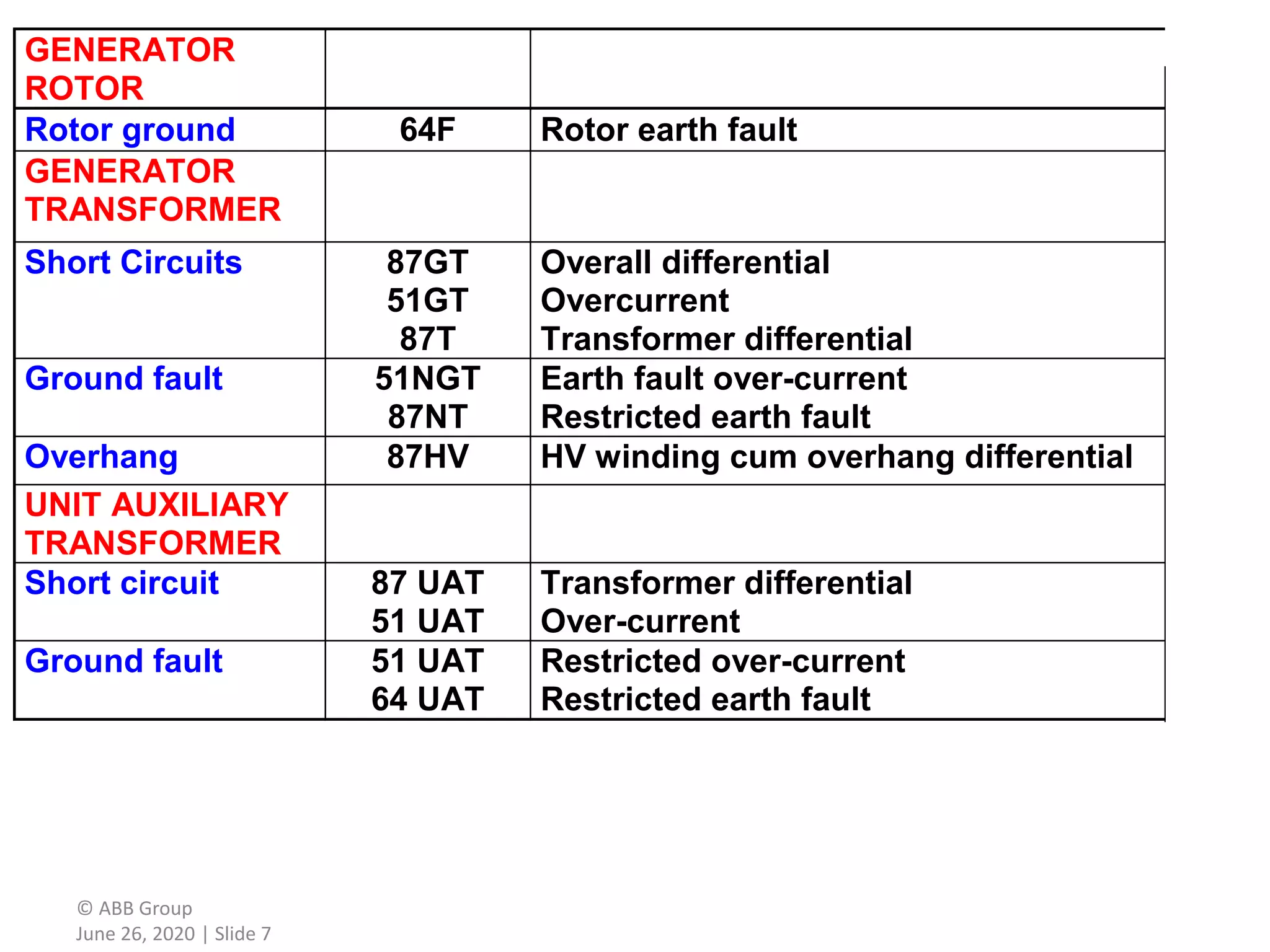
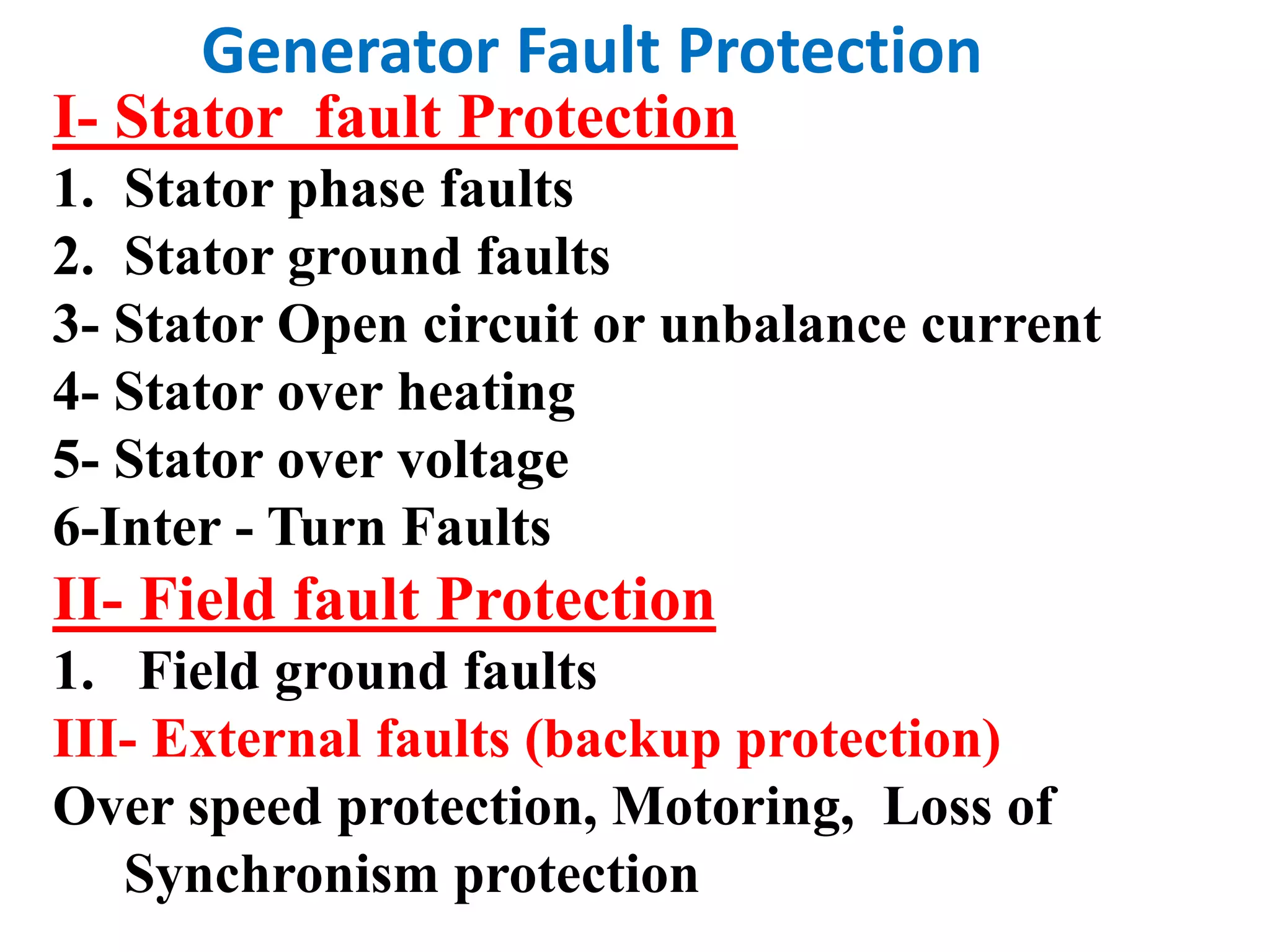
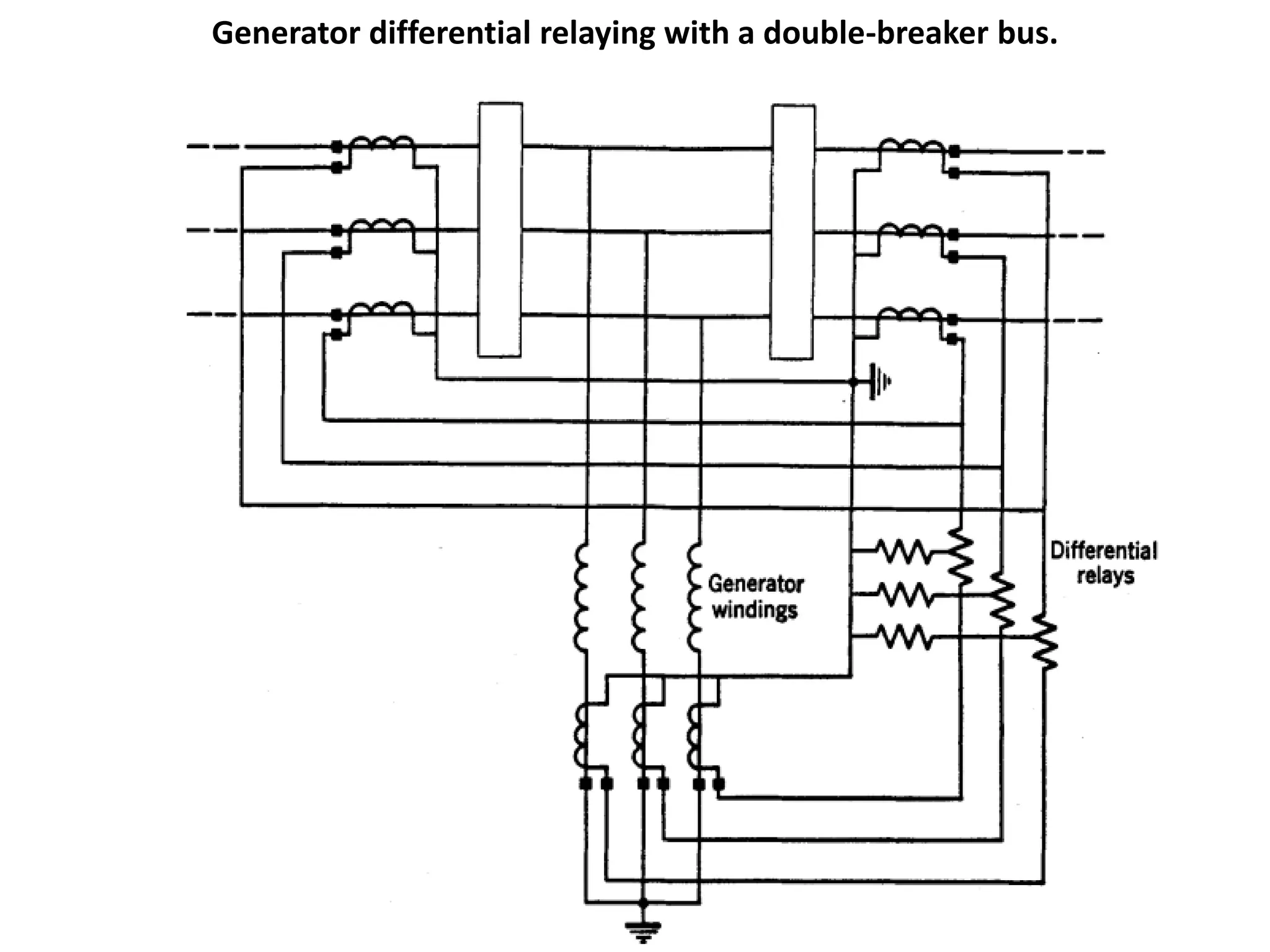
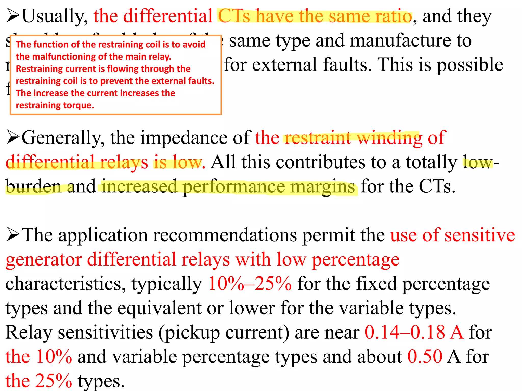
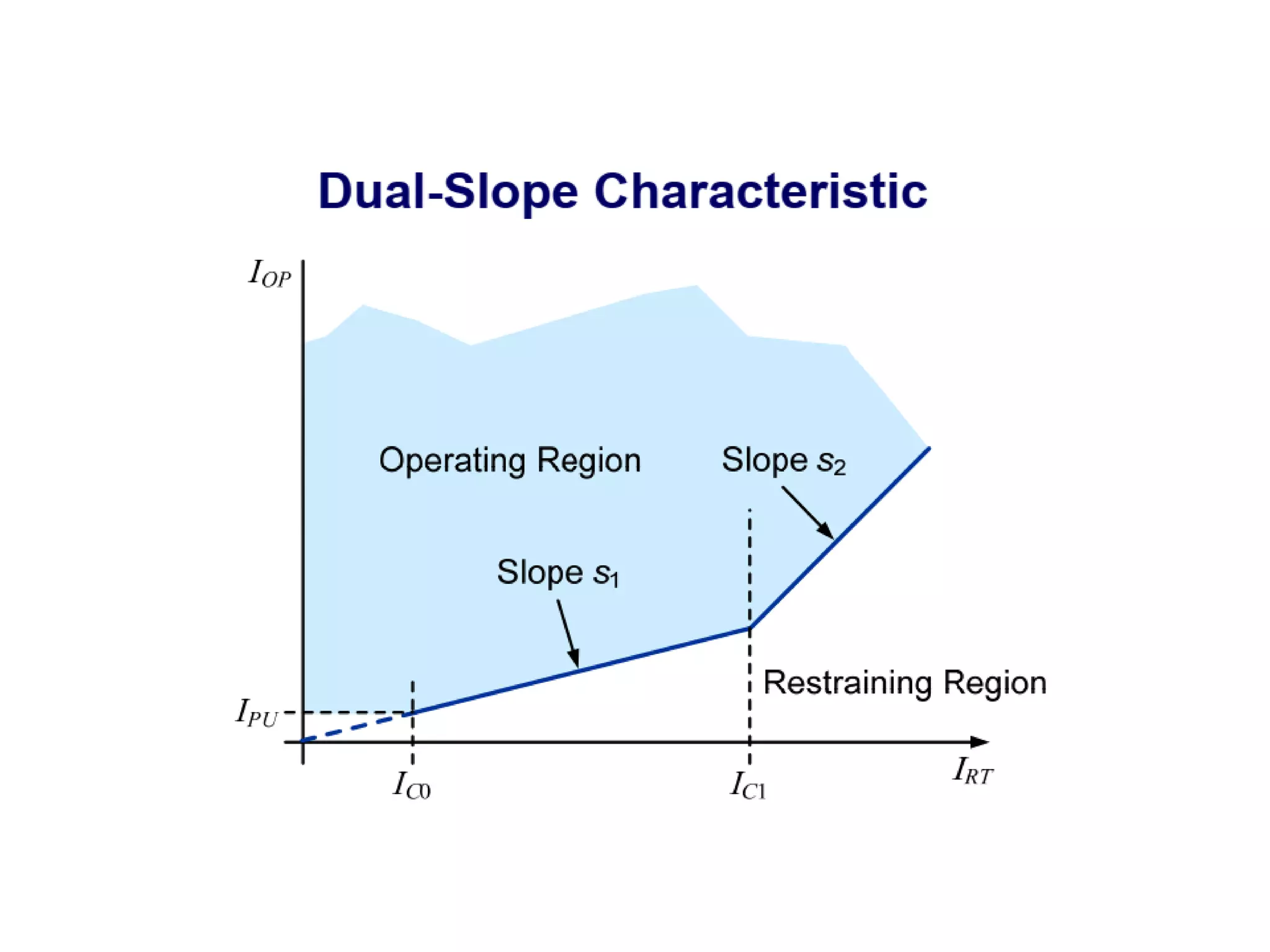
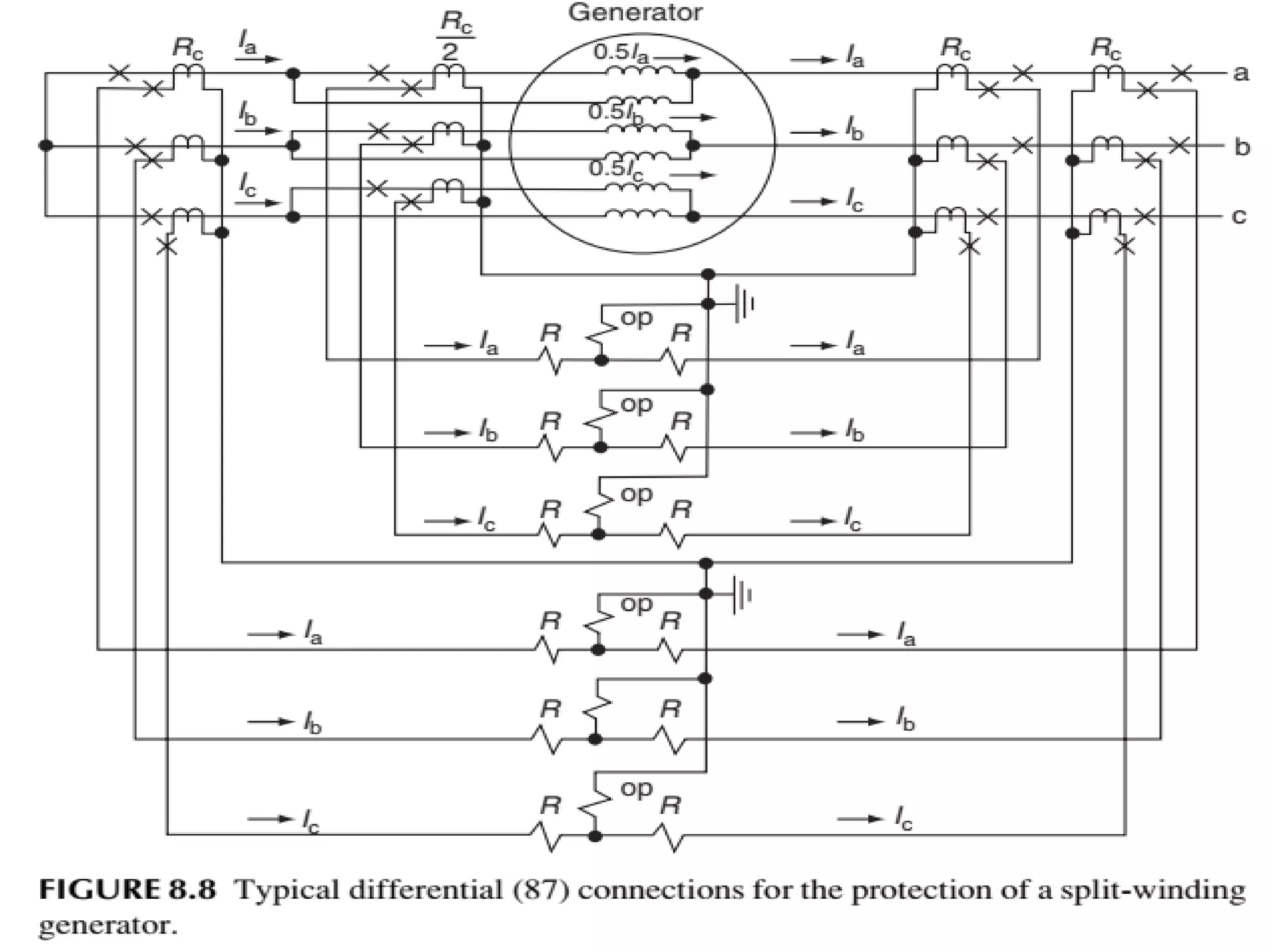
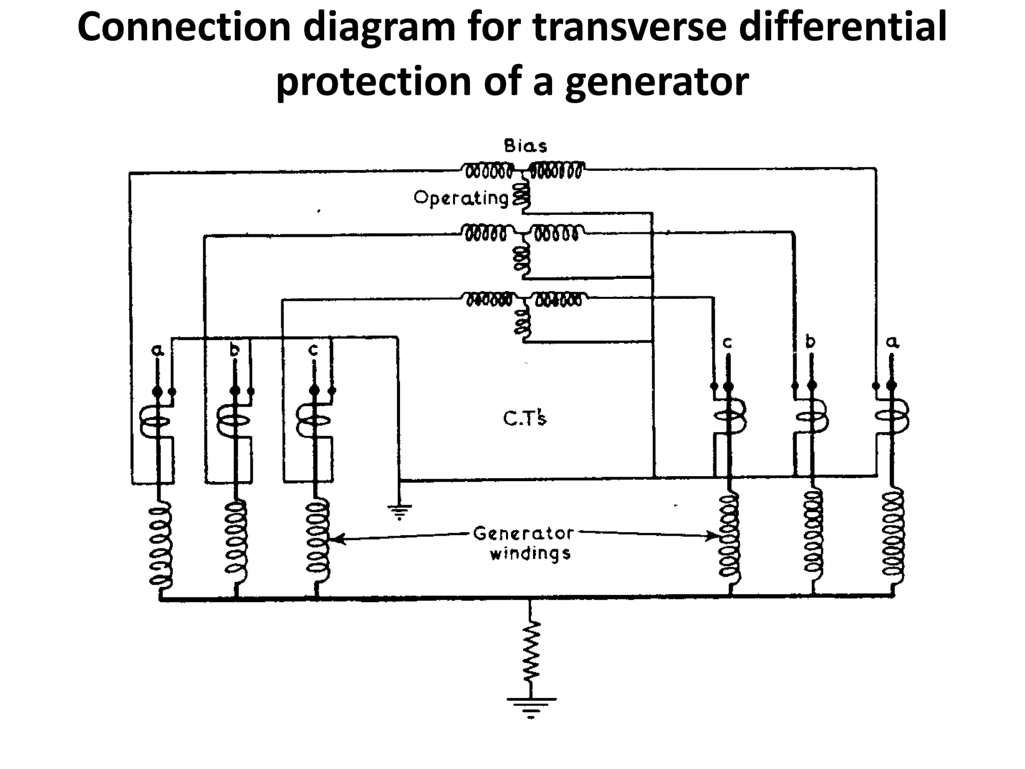
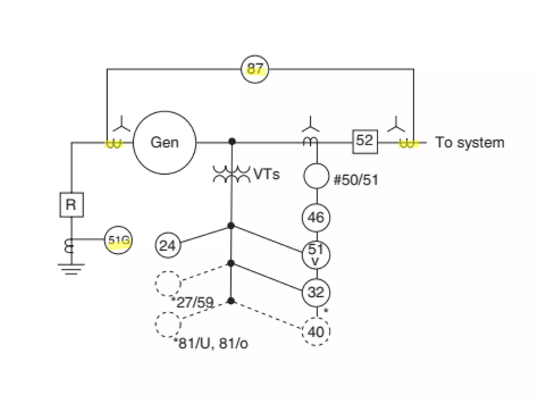
�The sample calculations shown here illustrate steps involved in calculating the relay settings for generator protection.
�Other methodologies and techniques may be applied to calculate relay settings based on specific applications.
The protections of generator are the most complex and elaborate due to the following reasons: Generator is a large machine, connected to bus-bars. It is accompanied by unit transformers, auxiliary transformers and a bus system. ... The protection of generator should be co-ordinate with associated equipment's.
Tutorial on Distance and Over Current ProtectionSARAVANAN A
Contents
• Protection Philosophy of ERPC
• Computation of Distance Relay Setting
• System Study to Understand Distance Relay
Behaviour
• DOC and DEF for EHV system
Practical handbook-for-relay-protection-engineersSARAVANAN A
The ‘Hand Book’ covers the Code of Practice in Protection Circuitry including standard lead and device numbers, mode of connections at terminal strips, colour codes in multicore cables, Dos and Donts in execution. Also, principles of various protective relays and schemes including special protection schemes like differential,
restricted, directional and distance relays are explained with sketches. The norms of protection of generators, transformers, lines & Capacitor Banks are also given.
How is power transformer protected??? This provides a basic understanding of power transformer. Furthermore, the protective relay application on power transformer is included.
Why do Transformers Fail?
�The electrical windings and the magnetic core in a transformer are subject to a number of different forces during operation, for example:
�Expansion and contraction due to thermal cycling
�Vibration
�Local heating due to magnetic flux
�Impact forces due to through-fault current
�Excessive heating due to overloading or inadequate cooling
This Presentation provides information about generator protection. All types of protection system which is used for generator are included in this presentation
Main equipment in the power plant is Generator. It's cost is much higher than any other equipment so we will have to protect the generator from all the possible faults and errors.
Generator and Transformer Protection (PART 1)Dr. Rohit Babu
Part 1. Generator Protection
Protection of generators against stator faults
Rotor faults and abnormal conditions
Restricted earth fault and inter-turn fault protection
Numerical examples
Need for protection
Nature and causes of faults
Types of faults
Fault current calculation using symmetrical components
Zones of protection
Primary and back up protection
Essential qualities of protection
Typical protection schemes.
This Presentation gives information on How Generator in Power Plants are protected with State of art technologies. Also provide information how latest Power System Protection technologies are more reliable operation.
Water scarcity is the lack of fresh water resources to meet the standard water demand. There are two type of water scarcity. One is physical. The other is economic water scarcity.
About
Indigenized remote control interface card suitable for MAFI system CCR equipment. Compatible for IDM8000 CCR. Backplane mounted serial and TCP/Ethernet communication module for CCR remote access. IDM 8000 CCR remote control on serial and TCP protocol.
• Remote control: Parallel or serial interface.
• Compatible with MAFI CCR system.
• Compatible with IDM8000 CCR.
• Compatible with Backplane mount serial communication.
• Compatible with commercial and Defence aviation CCR system.
• Remote control system for accessing CCR and allied system over serial or TCP.
• Indigenized local Support/presence in India.
• Easy in configuration using DIP switches.
Technical Specifications
Indigenized remote control interface card suitable for MAFI system CCR equipment. Compatible for IDM8000 CCR. Backplane mounted serial and TCP/Ethernet communication module for CCR remote access. IDM 8000 CCR remote control on serial and TCP protocol.
Key Features
Indigenized remote control interface card suitable for MAFI system CCR equipment. Compatible for IDM8000 CCR. Backplane mounted serial and TCP/Ethernet communication module for CCR remote access. IDM 8000 CCR remote control on serial and TCP protocol.
• Remote control: Parallel or serial interface
• Compatible with MAFI CCR system
• Copatiable with IDM8000 CCR
• Compatible with Backplane mount serial communication.
• Compatible with commercial and Defence aviation CCR system.
• Remote control system for accessing CCR and allied system over serial or TCP.
• Indigenized local Support/presence in India.
Application
• Remote control: Parallel or serial interface.
• Compatible with MAFI CCR system.
• Compatible with IDM8000 CCR.
• Compatible with Backplane mount serial communication.
• Compatible with commercial and Defence aviation CCR system.
• Remote control system for accessing CCR and allied system over serial or TCP.
• Indigenized local Support/presence in India.
• Easy in configuration using DIP switches.
Final project report on grocery store management system..pdfKamal Acharya
In today’s fast-changing business environment, it’s extremely important to be able to respond to client needs in the most effective and timely manner. If your customers wish to see your business online and have instant access to your products or services.
Online Grocery Store is an e-commerce website, which retails various grocery products. This project allows viewing various products available enables registered users to purchase desired products instantly using Paytm, UPI payment processor (Instant Pay) and also can place order by using Cash on Delivery (Pay Later) option. This project provides an easy access to Administrators and Managers to view orders placed using Pay Later and Instant Pay options.
In order to develop an e-commerce website, a number of Technologies must be studied and understood. These include multi-tiered architecture, server and client-side scripting techniques, implementation technologies, programming language (such as PHP, HTML, CSS, JavaScript) and MySQL relational databases. This is a project with the objective to develop a basic website where a consumer is provided with a shopping cart website and also to know about the technologies used to develop such a website.
This document will discuss each of the underlying technologies to create and implement an e- commerce website.
Saudi Arabia stands as a titan in the global energy landscape, renowned for its abundant oil and gas resources. It's the largest exporter of petroleum and holds some of the world's most significant reserves. Let's delve into the top 10 oil and gas projects shaping Saudi Arabia's energy future in 2024.
Sachpazis:Terzaghi Bearing Capacity Estimation in simple terms with Calculati...Dr.Costas Sachpazis
Terzaghi's soil bearing capacity theory, developed by Karl Terzaghi, is a fundamental principle in geotechnical engineering used to determine the bearing capacity of shallow foundations. This theory provides a method to calculate the ultimate bearing capacity of soil, which is the maximum load per unit area that the soil can support without undergoing shear failure. The Calculation HTML Code included.
Overview of the fundamental roles in Hydropower generation and the components involved in wider Electrical Engineering.
This paper presents the design and construction of hydroelectric dams from the hydrologist’s survey of the valley before construction, all aspects and involved disciplines, fluid dynamics, structural engineering, generation and mains frequency regulation to the very transmission of power through the network in the United Kingdom.
Author: Robbie Edward Sayers
Collaborators and co editors: Charlie Sims and Connor Healey.
(C) 2024 Robbie E. Sayers
2. From Lecture 1, We can say:
Generator hazards and problems are as follows:
A. Internal faults
1. Phase or ground faults in the stator and associated areas
(required primary and backup protection )
2. Ground faults in the rotor and loss-of-field excitation
(Mention the relay types according to generator rating)
B. System disturbances and operational hazards
1. Loss of prime-mover; generator motoring (32)
2. Overexcitation: volts or hertz protection (24)
3. Inadvertent energization: non synchronized connection (67)
4. Unbalanced currents: negative sequence (46); breaker pole
flashover (61)
5. Thermal overload (49)
Reverse Phase Relay
Thermal Relay
3. Continue
Generator hazards and problems are as follows:
6. Off-frequency operation for large steam turbines
7. Un cleared system faults: backup distance (21); voltage
controlled time over-current (50V)
8. Overvoltage (59)
9. Loss of synchronism: out of step
10. Sub-synchronous oscillations
11. Loss of voltage transformer signal to relaying or voltage
regulator
12. Generator breaker failure
Cut the fues of V.T
4. In the case of DG, additional protection is required at
the point of common coupling (PCC).
This protection also serves to protect the generator from
events that may originate on the utility power system.
Facilities at the PCC will typically consist of protection to
A- prevent islanded operation of the DG and part of the utility
system,
B- To assure that:
(1) the generator does not cause voltage and frequency on the
utility system to be outside the acceptable limits,
(2) the generator trips for required faults on the intertie line,
(3) faults on the distributed generator system are cleared by
the PCC breaker rather than by interrupting devices located on
the utility power system.
10. A- Differential protection for small generator units with flux
summation current transformers and an instantaneous over
current (50 relay). (Self-Balancing Differential)
11.
12.
13. ▪The limitation is the ability to pass the two conductors
through the window or opening of the CT. Typical opening
diameters are about 4–8 in. However, where this is possible,
high-sensitivity, high-speed protection is obtained, and CT
performance does not have to be matched, for there is only one
involved per phase.
➢ The flux summation CT ratio (commonly 50:5) is
independent of generator load current.
➢Typical sensitivities in the order of 5 A primary current can
be obtained.
➢This provides protection for both phase- and ground-fault
currents as long as the fault level for faults within the
differential zone is greater than the sensitivity.
14. Be Careful
This scheme does not provide protection to the connections
from the flux summation CT to the generator breaker, unless
the CT is on the bus side of the breaker and the generator
neutral side leads are carried to that point.
This is seldom practical, so other protection must be provided
for this area between the flux summation CT and the breaker.
In general, this scheme is more sensitive as long as the
generator CT ratio is greater than 150:5 to 200:5.
If the flux summation CT is not applicable and differential
protection is desired, the scheme of next Figure can be
used.
15. B- Typical differential (87) connections for the protection of
wye - and delta connected generators
19. ➢Usually, the differential CTs have the same ratio, and they
should preferably be of the same type and manufacture to
minimize mismatch errors for external faults. This is possible
for the unit generators
➢Generally, the impedance of the restraint winding of
differential relays is low. All this contributes to a totally low-
burden and increased performance margins for the CTs.
➢The application recommendations permit the use of sensitive
generator differential relays with low percentage
characteristics, typically 10%–25% for the fixed percentage
types and the equivalent or lower for the variable types.
Relay sensitivities (pickup current) are near 0.14–0.18 A for
the 10% and variable percentage types and about 0.50 A for
the 25% types.
The function of the restraining coil is to avoid
the malfunctioning of the main relay.
Restraining current is flowing through the
restraining coil is to prevent the external faults.
The increase the current increases the
restraining torque.
20. ➢The operating time should be fast to open the breaker(s),
remove the field, and initiate reduction of the prime-mover
input.
➢Unfortunately, the flux in the machine continues to supply
the fault for several seconds (about 8–16 sec), so instantaneous
de-energization of generator faults is not possible.
➢Problems with magnetizing inrush generally are not severe
because the voltage on the machine is developed gradually,
and the generator is carefully synchronized to the power
system.
21.
22. The Minimum Pickup region is used between zero and
approximately 0.5 per unit restraint current. It provides
security against CT remanence and accuracy errors and is
usually set between 0.3 and 0.5pu.
• The Slope 1 region is used between the minimum pickup
region and the slope 2 breakpoint. Slope 1 provides security
against false tripping due to CT accuracy. Class C CT
accuracy is +/‐10%, therefore 20% should be the absolute
minimum setting with greater than 30% preferred.
• The Slope 2 region is used above the slope 2 breakpoint,
which is normally set at 2pu. Slope 2 provides security
against false tripping during through fault events where CT
saturation is likely.
Above 2pu current, a significant DC current component will
be present and therefore saturation is likely. Slope 2 is
normally set at 60‐80%.
23. C- HIGH-IMPEDANCE VOLTAGE DIFFERENTIAL
PROTECTION FOR GENERATORS
The high-impedance voltage type of differential protection scheme can
be applied as an alternative to the current differential type described. The
relays are connected between phase and neutral leads of paralleled CTs.
For external faults, the voltage across the relay will be low, because the
current circulates between the two sets of CTs (see Figure 8.7).
For internal faults, the fault currents must pass through the exciting
branch and high impedance relay of each CT, so that the CTs are
saturated for most faults, producing a high voltage to operate the relay.
This protection scheme is widely used for bus protection and is described
further in Chapter 10. The CT requirements are more or less critical.
They should have identical characteristics, negligible leakage reactance,
and fully distributed secondary windings.
30. Split-winding generators, where the two winding
halves are available with CTs in one of the halves
(Figure 8.8), can be protected with two separate
differentials. By comparing one winding half against
the total, as shown, protection for shorted turns and
open-circuited windings is possible. This is difficult or
impossible for conventional relaying until the fault
develops into the other phases or the ground. Where a
2:1 CT ratio is not available, auxiliary CTs can be
used.
33. PHASE-FAULT BACKUP PROTECTION (51V) OR (21)
Backup protection for the generator and connected system
can be provided by a voltage-controlled or voltage-restraint
time-over current relay (51V) or by phase distance relays
(21). These two types are in wide use, with 51V generally
applied to medium and smaller generators, and 21V for
large-unit generators.
VOLTAGE-CONTROLLED OR VOLTAGE-RESTRAINT
TIME–OVERCURRENT (51V) BACKUP PROTECTION
This is a non directional relay; therefore, it can be connected
to CTs at the ground terminal or at the neutral end as in
Figure generator connection. Voltage is from the generator
voltage transformers (VTs) and is used to prevent the time
over current unit from operating, until a fault decreases the
voltage.
34.
35. PHASE-DISTANCE (21) BACKUP PROTECTION
On large generators, especially the unit types, phase-fault
backup is usually provided by phase-distance units (21). When
connected to CTs on the neutral side, backup is provided for
both the generator and the system. When using a three-phase
type 21 relay, the phase shift of the transformer does not affect
the reach, as it does for single-phase-type units. Voltage is
obtained from the VTs at the generator terminals.
For distance relays, the location of the CTs determines the
directional sensing, whereas distance is measured from the
location of the VTs. Thus, if CTs at the generator leads were
used, backup could be provided only for the system or for the
generator, but not both, depending on the connections. When
it is set such that it looks into the system, a fixed timer
provides the necessary time delay to coordinate with all the
relays its setting overreaches.