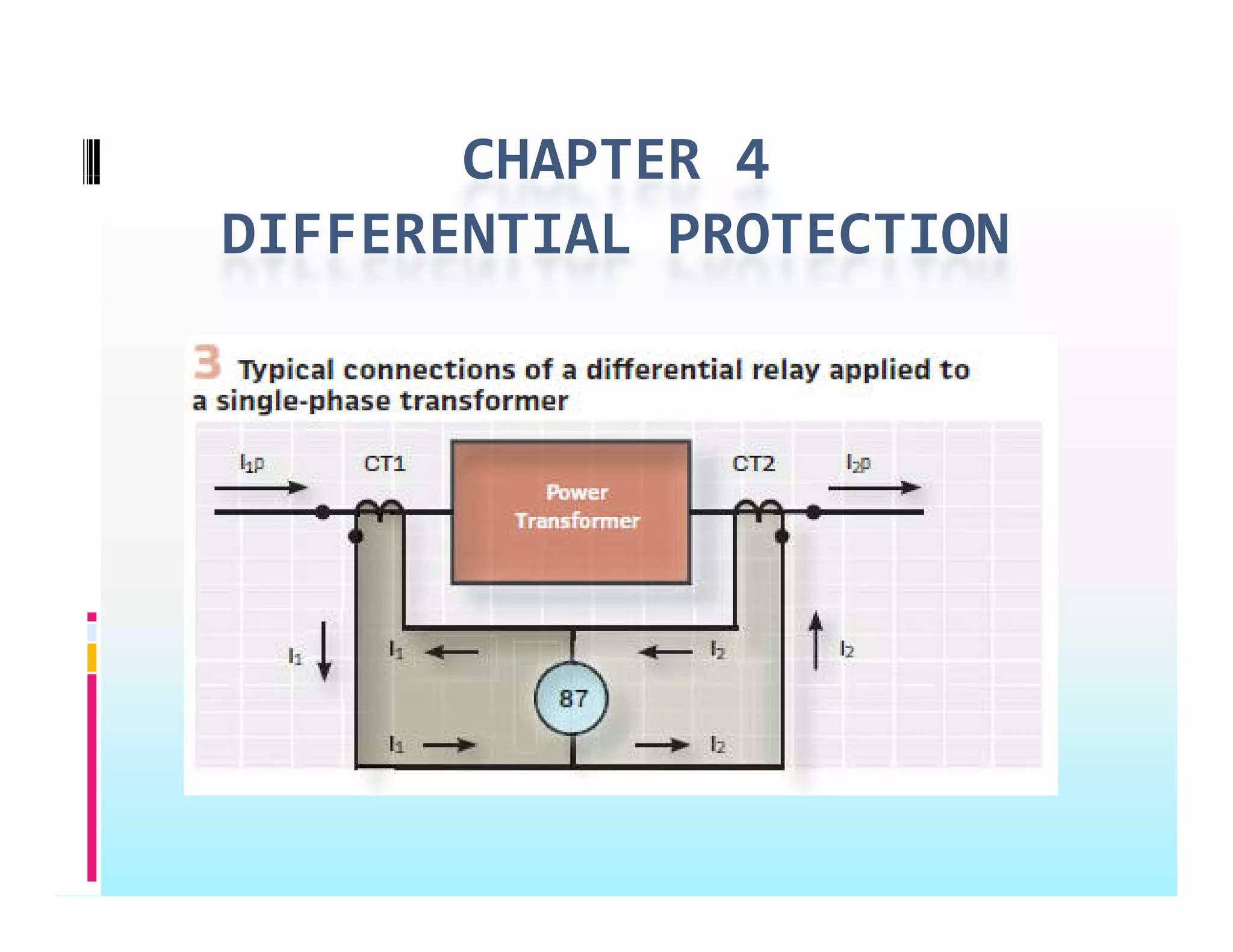
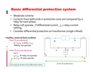
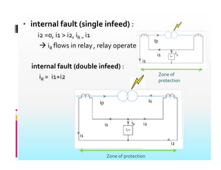
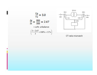
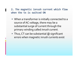
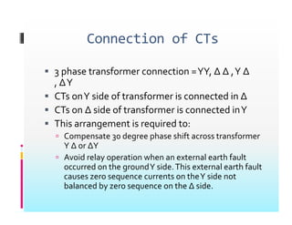
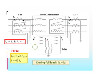
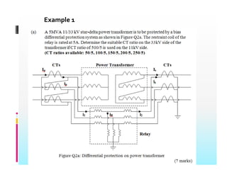
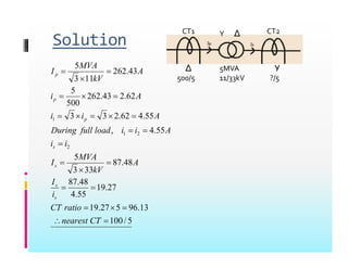
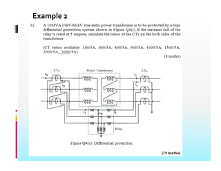
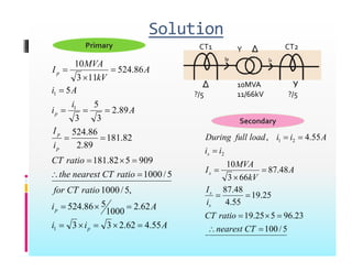
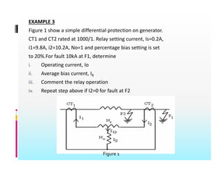
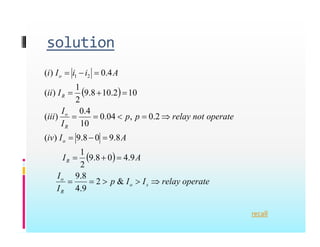
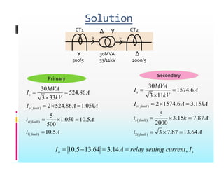
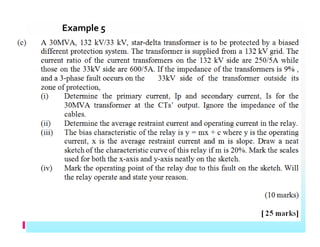
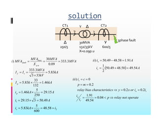
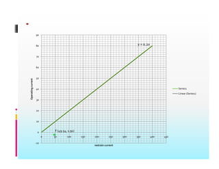
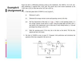
CHAPTER 4
CHAPTER 4
DIFFERENTIAL PROTECTION
Differential protection principle is used in the
following applications.
g pp
1. Protection of generator, protection of generator
transformer unit.
2 Protection of transformer
2. Protection of transformer
3. Protection of feeder (transmission line) by pilot
wire differential protection.
P i f i i li b h
4. Protection of transmission line by phase
comparison carrier current protection.
5. Protection of large motor.
5 g
6. Bus‐zone protection.
Intro.
Intro.
 Differential protection is a unit scheme that
compares the current on the primary side of a
transformer with that on the secondary side.
y
 Where a difference exists, it is assumed that the
transformer has developed a fault and the plant
i i ll di d b i i h
is automatically disconnected by tripping the
relevant circuit breakers.
 The principle of operation is made based of the
fact that large transformers are very efficient
and hence under normal operation power‐in
equals power‐out.
Cont….
 This scheme is used for tx ≥ 5MVA
 Normally used on generators & transformers. Also
d li & b b
used to protect lines & busbars.
 2 CTs used to monitor protection zone
 Signals from both ends of the CTs are compared by
differential relay
 CB will trip if the quantity that has been compared is
p q y p
different from setting value; meaning that a fault
has occurred within protection zone (internal fault)
 External fault should not affect the CB (CB not trip)
 2 schemes of differential protection system:
 Basic differential protection system
p y
 Bias/restrain differential protection system
Basic differential protection system
 Moderate scheme
 Currents from both ends in protection zone are compared by a
relay for each phase
 Relay will operate , if differential current , iR > relay current
setting,
 Consider differential protection on transformer (single infeed):
Consider differential protection on transformer (single infeed):
• healthy / external fault condition
•the CTs are identical: I Is
> >
the CTs are identical:
i1 = i2, iR = 0 and iR < iset
Relay not operate
Ip Is
i i2
i
<
<
>
• the CTs are not identical:
i1≠ i2
iR < iset  relay not operate
iR > iset  relay operate
i1 i2
iR
<
i1
>
i2
>
iR > iset  relay operate
Zone of protection
i2
Cause tripping Lead to bias differential scheme
• internal fault (single infeed) :
i2 =0, i1 > i2, iR = i1
 iR flows in relay, relay operate
Ip
i
>
<
>
internal fault (double infeed) :
i i i Zone of
i1 i1
i1
>
iR = i1+i2 Zone of
protection
>
>
Ip Is
>
>
i1 i2
iR
<
<
>
i1
>
Zone of protection
i2
Problem with basic differential relay
1. CT ratio mismatch
 The two CT must be perfectly matched
 For feeder or generator – the CTs must have same ratio
 For transformer ;
 The CT ratios must be carefully chosen to minimize the
normal differential c rrent
normal differential current
Ideal Case
= 11% unbalance









%
11
%
100
67
.
2
3
CT ratio mismatch




%
%
00
3
2. The magnetic inrush current which flow
Wh f i i i i ll d
when the tx is switced ON
 When a transformer is initially connected to a
source of AC voltage, there may be a
substantial surge of current through the
primary winding called inrush current.
Th CT b b t ti l @ i ifi t
 Thus, CT can be substantial @ significant
errors when magnetic inrush currents exist
BIAS DIFFERENTIAL PROTECTION
SYSTEM
SYSTEM
 2 set of coils
2 set of coils
 Operating coil
 Uses differential current to operate the relay
Uses differential current to operate the relay
 Restraining coil
 2 halves of a bias coil
2 halves of a bias coil
 Uses average fault current to restrain the relay from
operating
Currents flowing in the 2 coils
produce opposing magnetic field
The magnetic fields produce
g p
opposing torques on an induction
disc
When the torque produced by the
operating coil’s magnetic field
exceeds that of the restraining coil
& the spring, the relay will operate
I
I
current
operating
I
I
I
p
I
c
x
m
y
o
set
r
o







2
1
 
I
I
current
g
restrainin
average
I
I
I
current
operating
I
r
o



2
1
2
1
1
 
I
I
setting
bias
p
r
o


2
1
2
current
setting
relay
Iset 
EG 3
d f l
2 conditions for relay’s operation:
 Io> Iset
I
 p
I
I
R
o

Connection of CTs
Connection of CTs
 3 phase transformer connection YY ∆ ∆ Y ∆
 3 phase transformer connection =YY, ∆ ∆ ,Y ∆
, ∆Y
 CTs onY side of transformer is connected in ∆
CTs onY side of transformer is connected in ∆
 CTs on ∆ side of transformer is connected inY
 This arrangement is required to:
This arrangement is required to:
 Compensate 30 degree phase shift across transformer
Y ∆ or ∆Y
A id l ti h t l th f lt
 Avoid relay operation when an external earth fault
occurred on the groundY side.This external earth fault
causes zero sequence currents on theY side not
b l d b h ∆ id
balanced by zero sequence on the ∆ side.
2
1 & i
i
i
i 
 2
1 & i
i
i
i s
p
For ∆ :
load
line
i
i
I
I
3
3
1 
 
For ∆ :
p
i
i 3
1
During full load : i1 = i2
Example 1
Solution
Y Δ
CT1 CT2
43
.
262
11
3
5


 A
kV
MVA
Ip
5MVA
11/33kV
Δ
500/5
Y
?/5
55
4
62
2
3
3
62
.
2
43
.
262
500
5








A
i
i
A
ip
55
.
4
,
55
.
4
62
.
2
3
3
2
2
1
1








i
i
A
i
i
load
full
During
A
i
i
s
p
27
19
48
.
87
48
.
87
33
3
5



I
A
kV
MVA
I
s
s
5
/
100
13
.
96
5
27
.
19
27
.
19
55
.
4
8
.
87





CT
ratio
CT
is
s
5
/
100

 CT
nearest
Example 2
Solution
Primary Y Δ
CT1 CT2
A
kV
MVA
Ip 86
.
524
11
3
10



10MVA
Y Δ
Δ Y
A
i
i
A
i
p 89
.
2
3
5
3
5
1
1




S d
10MVA
11/66kV
Δ
?/5
Y
?/5
i
I
p
p
82
.
181
89
.
2
86
.
524
3
3

 55
.
4
,
2
2
1



i
i
A
i
i
load
full
During
Secondary
i
CT
f
ratio
CT
nearest
the
ratio
CT
5
/
1000
5
/
1000
909
5
82
.
181





48
87
48
.
87
66
3
10
2



I
A
kV
MVA
I
i
i
s
s
A
i
ratio
CT
for
p 62
.
2
1000
5
86
.
524
,
5
/
1000



23
.
96
5
25
.
19
25
.
19
55
.
4
48
.
87





ratio
CT
i
I
s
s
A
i
i p 55
.
4
62
.
2
3
3
1 



 5
/
100

 CT
nearest
EXAMPLE 3
Figure 1 show a simple differential protection on generator
Figure 1 show a simple differential protection on generator.
CT1 and CT2 rated at 1000/1. Relay setting current, Is=0.2A,
i1=9.8A, i2=10.2A, No=1 and percentage bias setting is set
to 20%.For fault 10kA at F1, determine
i. Operating current, Io
ii Average bias current IR
ii. Average bias current, IR
iii. Comment the relay operation
iv. Repeat step above if I2=0 for fault at F2
Figure 1
solution
solution
A
i
i
I
i o 

 4
.
0
)
( 2
1
 
I
I
ii R
o



4
0
10
2
.
10
8
.
9
2
1
)
(
)
( 2
1
A
I
iv
operate
not
relay
p
p
I
I
iii
R
o








8
9
0
8
9
)
(
2
.
0
,
04
.
0
10
4
.
0
)
(
  A
I
A
I
iv
R
o





9
.
4
0
8
.
9
2
1
8
.
9
0
8
.
9
)
(
operate
relay
I
I
p
I
I
s
o
R
o




 &
2
9
.
4
8
.
9
recall
Example 4
Solution
Δ Y
CT1 CT2
30MVA
Δ Y
Y Δ
Secondary
30MVA
33/11kV
Y
500/5
Δ
2000/5
A
kV
MVA
Is 6
.
1574
11
3
30



Primary
Secondary
A
kV
MVA
Is 86
.
524
33
3
30



A
k
i
kA
A
I
f l
fault
s
87
7
15
3
5
15
.
3
6
.
1574
2
)
(
)
(






A
k
i
kA
A
I
kV
fault
s
5
10
05
1
5
05
.
1
86
.
524
2
33
3
)
(







A
i
A
k
i
fault
fault
s
64
.
13
87
.
7
3
87
.
7
15
.
3
2000
)
(
2
)
(




A
i
A
k
i
fault
fault
s
5
.
10
5
.
10
05
.
1
500
)
(
1
)
(




s
o I
current
setting
relay
A
I ,
14
.
3
64
.
13
5
.
10 



Example 5
solution
Y Δ
CT1 CT2
30MVA
132/33kV
X=0.09p.u
Δ
250/5
Y
600/5
3phase fault
.
3
333
3
.
333
09
.
0
30
)
A
MVA
MVA
X
MVA
MVA
i
u
p
base
fault 


  A
i
A
i
ii o
54
49
58
48
49
50
1
91
.
1
58
.
48
49
.
50
)






46
.
1
132
33
83
.
5
83
.
5
33
3
3
.
333
kA
k
I
kA
kV
MVA
I
I
p
s
f







  A
ir 54
.
49
58
.
48
49
.
50
2

c
i
iii s 

2
0
0
)
49
50
3
15
29
15
.
29
250
5
46
.
1
132
A
i
A
kA
ip
p



operate
not
relay
p
i
i
i
i
or
x
y
stics
characteri
bias
relay
m
p
o
r
o









04
.
0
54
49
91
.
1
2
.
0
2
.
0
2
.
0
2
1
58
.
48
600
5
83
.
5
49
.
50
3
15
.
29
i
kA
i
A
i
s 





 ir 54
.
49
y = 0.2x
80
90
60
70
40
50
erating
current
Series1
Linear (Series1)
20
30
Ope
0
10
0 50 100 150 200 250 300 350 400 450
F (49.54, 1.91)
‐10
5 5 5 3 35 4 45
restrain current
Example 6
(Assignment 3)
( g 3)

4_Differential Protection_rar(1).pdf

  • 1.
  • 2.
    Differential protection principleis used in the following applications. g pp 1. Protection of generator, protection of generator transformer unit. 2 Protection of transformer 2. Protection of transformer 3. Protection of feeder (transmission line) by pilot wire differential protection. P i f i i li b h 4. Protection of transmission line by phase comparison carrier current protection. 5. Protection of large motor. 5 g 6. Bus‐zone protection.
  • 3.
    Intro. Intro.  Differential protectionis a unit scheme that  Differential protection is a unit scheme that compares the current on the primary side of a transformer with that on the secondary side. y  Where a difference exists, it is assumed that the transformer has developed a fault and the plant i i ll di d b i i h is automatically disconnected by tripping the relevant circuit breakers.  The principle of operation is made based of the  The principle of operation is made based of the fact that large transformers are very efficient and hence under normal operation power‐in equals power‐out.
  • 4.
    Cont….  This schemeis used for tx ≥ 5MVA  Normally used on generators & transformers. Also d li & b b used to protect lines & busbars.  2 CTs used to monitor protection zone  Signals from both ends of the CTs are compared by  Signals from both ends of the CTs are compared by differential relay  CB will trip if the quantity that has been compared is p q y p different from setting value; meaning that a fault has occurred within protection zone (internal fault)  External fault should not affect the CB (CB not trip)  External fault should not affect the CB (CB not trip)  2 schemes of differential protection system:  Basic differential protection system p y  Bias/restrain differential protection system
  • 5.
    Basic differential protectionsystem  Moderate scheme  Currents from both ends in protection zone are compared by a relay for each phase relay for each phase  Relay will operate , if differential current , iR > relay current setting,  Consider differential protection on transformer (single infeed): Consider differential protection on transformer (single infeed): • healthy / external fault condition •the CTs are identical: I Is > > the CTs are identical: i1 = i2, iR = 0 and iR < iset Relay not operate Ip Is i i2 i < < > • the CTs are not identical: i1≠ i2 iR < iset  relay not operate iR > iset  relay operate i1 i2 iR < i1 > i2 > iR > iset  relay operate Zone of protection i2 Cause tripping Lead to bias differential scheme
  • 6.
    • internal fault(single infeed) : i2 =0, i1 > i2, iR = i1  iR flows in relay, relay operate Ip i > < > internal fault (double infeed) : i i i Zone of i1 i1 i1 > iR = i1+i2 Zone of protection > > Ip Is > > i1 i2 iR < < > i1 > Zone of protection i2
  • 7.
    Problem with basicdifferential relay 1. CT ratio mismatch  The two CT must be perfectly matched  For feeder or generator – the CTs must have same ratio  For transformer ;  The CT ratios must be carefully chosen to minimize the normal differential c rrent normal differential current Ideal Case
  • 8.
  • 9.
    2. The magneticinrush current which flow Wh f i i i i ll d when the tx is switced ON  When a transformer is initially connected to a source of AC voltage, there may be a substantial surge of current through the substantial surge of current through the primary winding called inrush current. Th CT b b t ti l @ i ifi t  Thus, CT can be substantial @ significant errors when magnetic inrush currents exist
  • 10.
    BIAS DIFFERENTIAL PROTECTION SYSTEM SYSTEM 2 set of coils 2 set of coils  Operating coil  Uses differential current to operate the relay Uses differential current to operate the relay  Restraining coil  2 halves of a bias coil 2 halves of a bias coil  Uses average fault current to restrain the relay from operating
  • 11.
    Currents flowing inthe 2 coils produce opposing magnetic field The magnetic fields produce g p opposing torques on an induction disc When the torque produced by the operating coil’s magnetic field exceeds that of the restraining coil exceeds that of the restraining coil & the spring, the relay will operate
  • 12.
  • 13.
    d f l 2conditions for relay’s operation:  Io> Iset I  p I I R o 
  • 14.
    Connection of CTs Connectionof CTs  3 phase transformer connection YY ∆ ∆ Y ∆  3 phase transformer connection =YY, ∆ ∆ ,Y ∆ , ∆Y  CTs onY side of transformer is connected in ∆ CTs onY side of transformer is connected in ∆  CTs on ∆ side of transformer is connected inY  This arrangement is required to: This arrangement is required to:  Compensate 30 degree phase shift across transformer Y ∆ or ∆Y A id l ti h t l th f lt  Avoid relay operation when an external earth fault occurred on the groundY side.This external earth fault causes zero sequence currents on theY side not b l d b h ∆ id balanced by zero sequence on the ∆ side.
  • 15.
    2 1 & i i i i  2 1 & i i i i s p For ∆ : load line i i I I 3 3 1    For ∆ : p i i 3 1 During full load : i1 = i2
  • 16.
  • 17.
    Solution Y Δ CT1 CT2 43 . 262 11 3 5   A kV MVA Ip 5MVA 11/33kV Δ 500/5 Y ?/5 55 4 62 2 3 3 62 . 2 43 . 262 500 5         A i i A ip 55 . 4 , 55 . 4 62 . 2 3 3 2 2 1 1         i i A i i load full During A i i s p 27 19 48 . 87 48 . 87 33 3 5    I A kV MVA I s s 5 / 100 13 . 96 5 27 . 19 27 . 19 55 . 4 8 . 87      CT ratio CT is s 5 / 100   CT nearest
  • 18.
  • 19.
    Solution Primary Y Δ CT1CT2 A kV MVA Ip 86 . 524 11 3 10    10MVA Y Δ Δ Y A i i A i p 89 . 2 3 5 3 5 1 1     S d 10MVA 11/66kV Δ ?/5 Y ?/5 i I p p 82 . 181 89 . 2 86 . 524 3 3   55 . 4 , 2 2 1    i i A i i load full During Secondary i CT f ratio CT nearest the ratio CT 5 / 1000 5 / 1000 909 5 82 . 181      48 87 48 . 87 66 3 10 2    I A kV MVA I i i s s A i ratio CT for p 62 . 2 1000 5 86 . 524 , 5 / 1000    23 . 96 5 25 . 19 25 . 19 55 . 4 48 . 87      ratio CT i I s s A i i p 55 . 4 62 . 2 3 3 1      5 / 100   CT nearest
  • 20.
    EXAMPLE 3 Figure 1show a simple differential protection on generator Figure 1 show a simple differential protection on generator. CT1 and CT2 rated at 1000/1. Relay setting current, Is=0.2A, i1=9.8A, i2=10.2A, No=1 and percentage bias setting is set to 20%.For fault 10kA at F1, determine i. Operating current, Io ii Average bias current IR ii. Average bias current, IR iii. Comment the relay operation iv. Repeat step above if I2=0 for fault at F2 Figure 1
  • 21.
    solution solution A i i I i o   4 . 0 ) ( 2 1   I I ii R o    4 0 10 2 . 10 8 . 9 2 1 ) ( ) ( 2 1 A I iv operate not relay p p I I iii R o         8 9 0 8 9 ) ( 2 . 0 , 04 . 0 10 4 . 0 ) (   A I A I iv R o      9 . 4 0 8 . 9 2 1 8 . 9 0 8 . 9 ) ( operate relay I I p I I s o R o      & 2 9 . 4 8 . 9 recall
  • 22.
  • 23.
    Solution Δ Y CT1 CT2 30MVA ΔY Y Δ Secondary 30MVA 33/11kV Y 500/5 Δ 2000/5 A kV MVA Is 6 . 1574 11 3 30    Primary Secondary A kV MVA Is 86 . 524 33 3 30    A k i kA A I f l fault s 87 7 15 3 5 15 . 3 6 . 1574 2 ) ( ) (       A k i kA A I kV fault s 5 10 05 1 5 05 . 1 86 . 524 2 33 3 ) (        A i A k i fault fault s 64 . 13 87 . 7 3 87 . 7 15 . 3 2000 ) ( 2 ) (     A i A k i fault fault s 5 . 10 5 . 10 05 . 1 500 ) ( 1 ) (     s o I current setting relay A I , 14 . 3 64 . 13 5 . 10    
  • 24.
  • 25.
    solution Y Δ CT1 CT2 30MVA 132/33kV X=0.09p.u Δ 250/5 Y 600/5 3phasefault . 3 333 3 . 333 09 . 0 30 ) A MVA MVA X MVA MVA i u p base fault      A i A i ii o 54 49 58 48 49 50 1 91 . 1 58 . 48 49 . 50 )       46 . 1 132 33 83 . 5 83 . 5 33 3 3 . 333 kA k I kA kV MVA I I p s f          A ir 54 . 49 58 . 48 49 . 50 2  c i iii s   2 0 0 ) 49 50 3 15 29 15 . 29 250 5 46 . 1 132 A i A kA ip p    operate not relay p i i i i or x y stics characteri bias relay m p o r o          04 . 0 54 49 91 . 1 2 . 0 2 . 0 2 . 0 2 1 58 . 48 600 5 83 . 5 49 . 50 3 15 . 29 i kA i A i s        ir 54 . 49
  • 26.
    y = 0.2x 80 90 60 70 40 50 erating current Series1 Linear(Series1) 20 30 Ope 0 10 0 50 100 150 200 250 300 350 400 450 F (49.54, 1.91) ‐10 5 5 5 3 35 4 45 restrain current
  • 27.