Downloaded 154 times
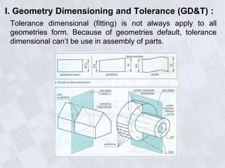
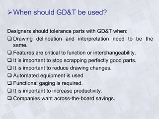

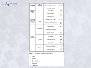
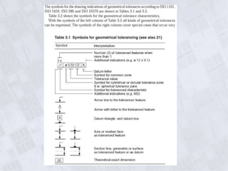
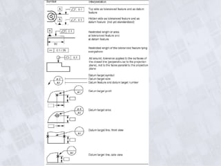
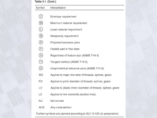
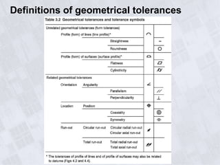
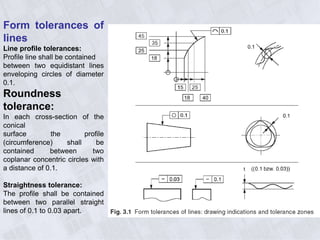
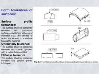


This document provides information on geometry dimensioning and tolerance. It defines dimensional tolerances and discusses their importance in assembly. It then discusses geometric dimensioning and tolerancing (GD&T), including its advantages over traditional tolerancing methods. The document outlines various GD&T symbols and their definitions, including form, orientation, location, runout, and other tolerances. It clarifies the differences between tolerances such as coaxiality and radial runout. Finally, it presents possibilities for geometrically tolerancing different features.


![Ppt Fits Tolerances[1]](https://cdn.slidesharecdn.com/ss_thumbnails/pptfitstolerances1-091107045206-phpapp01-thumbnail.jpg?width=640&height=640&fit=bounds)


