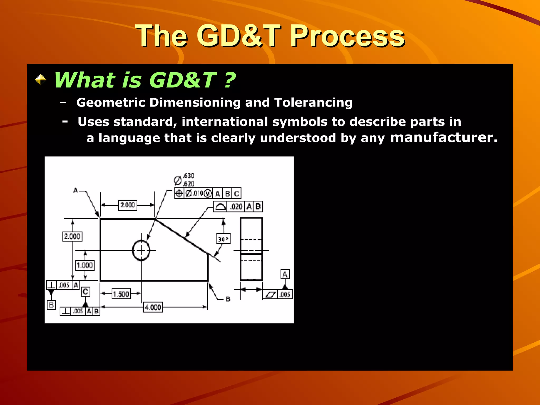
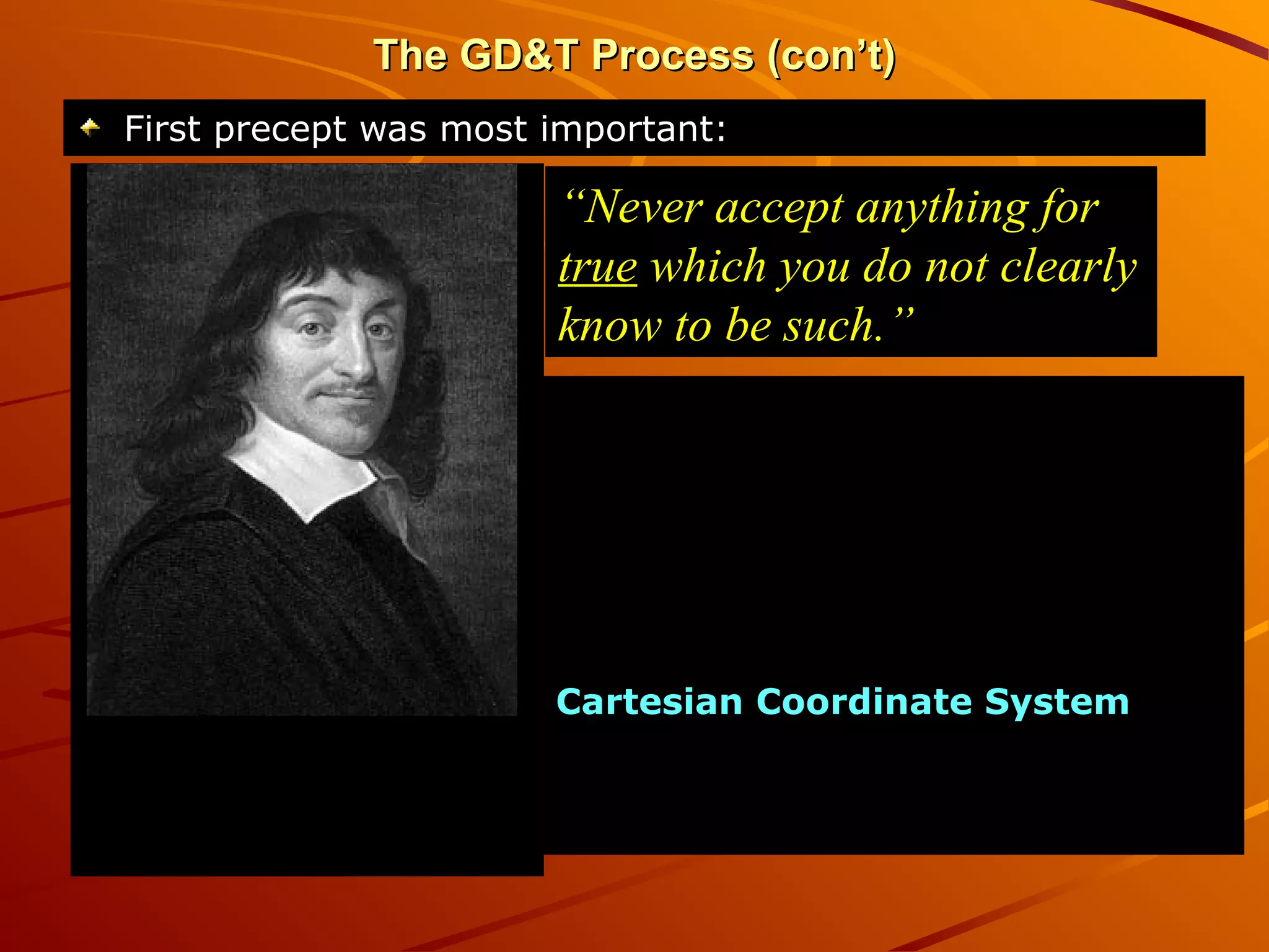
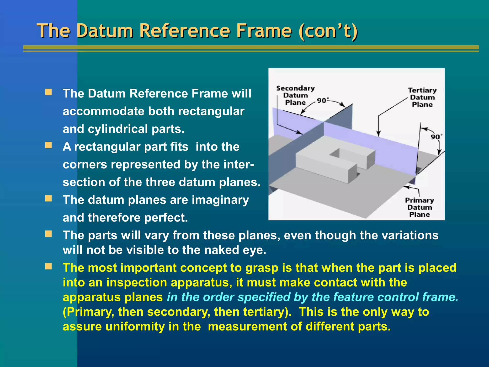
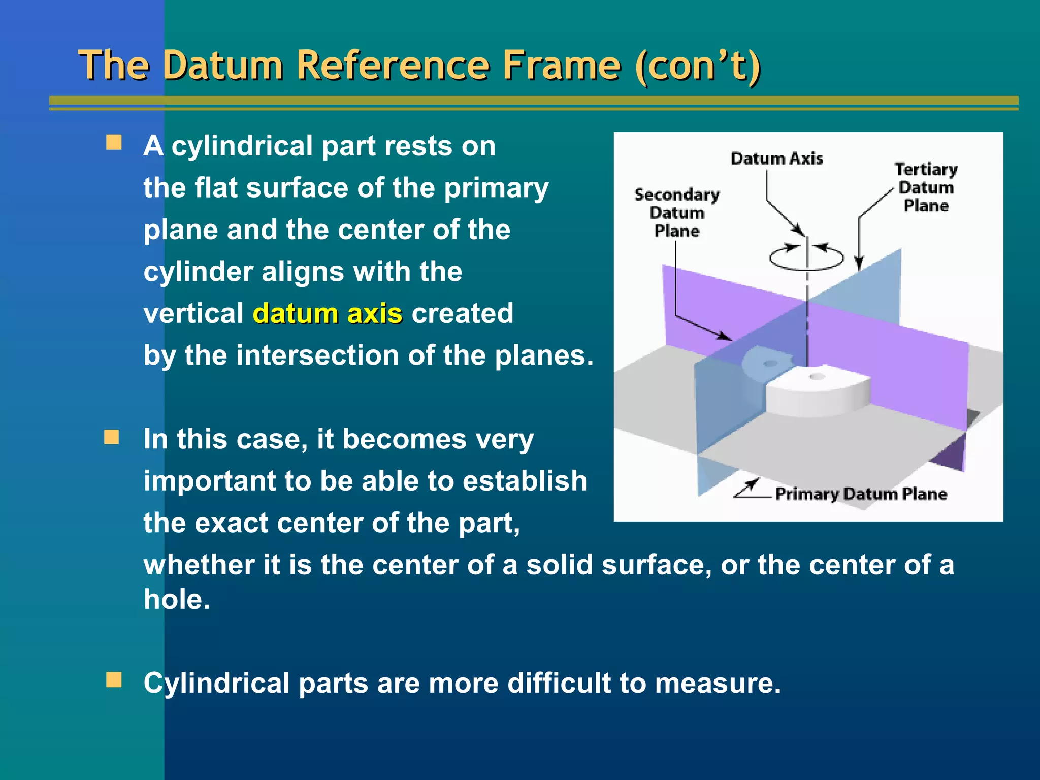
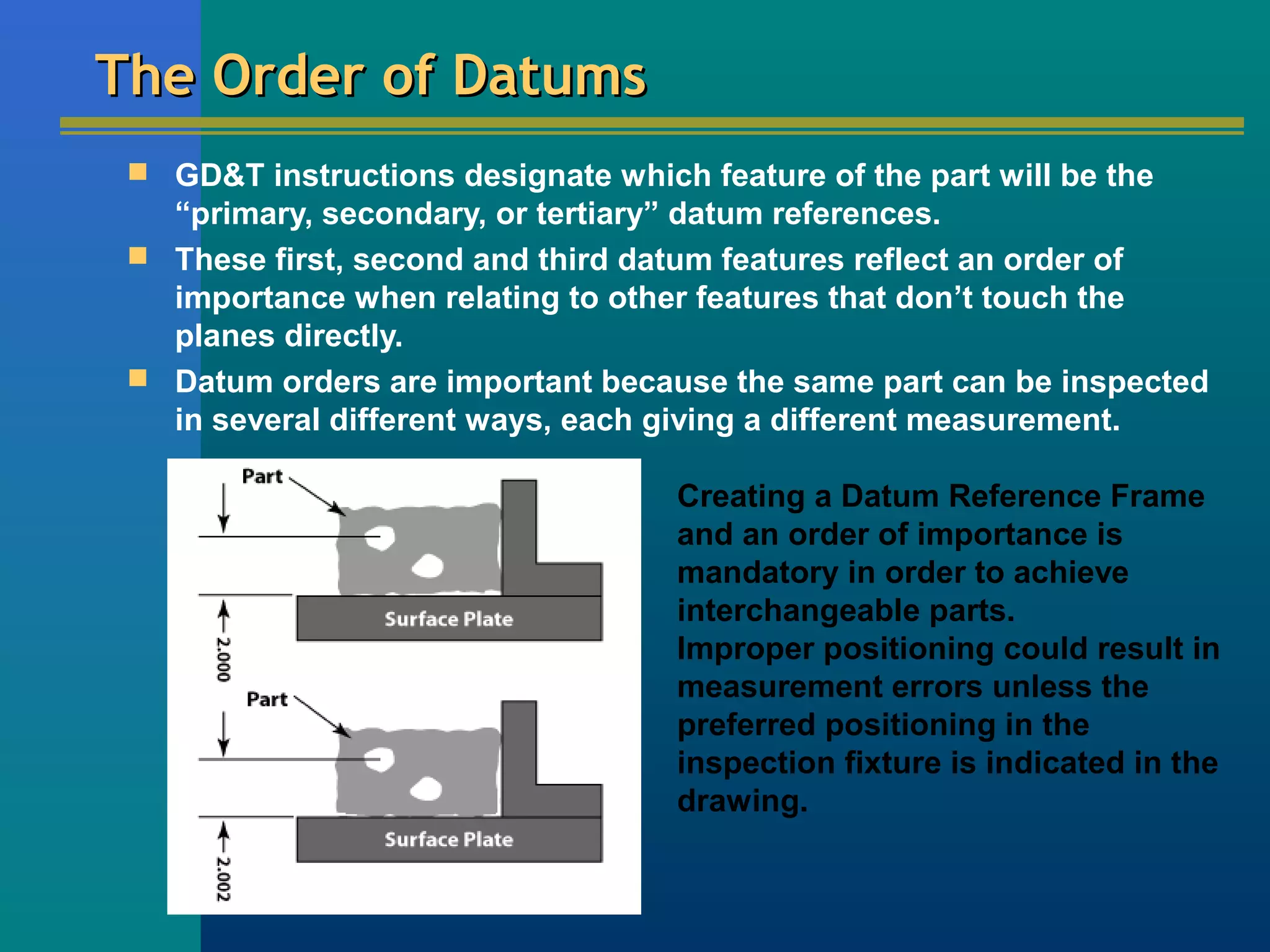
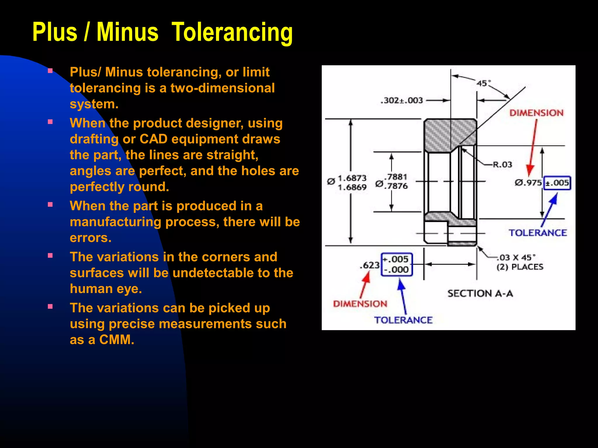
This document provides an overview of geometric dimensioning and tolerancing (GD&T). It defines GD&T as using standard symbols to describe parts in a precise language understood internationally. GD&T is an improvement over traditional dimensioning methods as it describes the form, fit, and function of parts using three zones of tolerance relative to a Cartesian coordinate system. The document outlines key GD&T concepts like datum reference frames, geometric tolerance zones, and feature control frames. It explains that GD&T precisely controls the position and profile of features to ensure interchangeability.
GD&T stands for Geometric Dimensioning and Tolerancing, as defined by ASME Y14.5.Geometric tolerancing, is an exact language that enables designers to “say what they mean” on a drawing, thus improving product designs.
Production uses the language to interpret the design intent, and Inspection looks to the language to determine set up.
GD&T is a method for stating and interpreting mechanical engineering design requirements. GD&T is a very useful & efficient tool to make engineering drawings a better means of communication from design through manufacturing and inspection.
GD&T: An International Language & and an Exact Language that provides Uniformity.
Geometric dimensioning and tolerancing is the new way of describing the dimensions and tolerances. It developed by engineers and used by engineers in engineering drawings or drafting. It plays a very important role in engineering design.
This presentation contains all the basic information about GD&T.
A basic 2 day training on understanding of GDnT,Geometrical Dimensioning & Tolerancing to Technical & Egineering Group as a common language in understanding Drawings.
Trainer & Speaker
Timothy Wooi,
20C,Taman Bahagia,06000,Jitra, Kedah. Malaysia
email: timothywooi2@gmail.com
GD&T is a means of dimensioning & tolerancing a drawing which considers the function of the part and how this part functions with related parts.
GD&T has increased in practice in last 15 years because of ISO 9000.
ISO 9000 requires not only that something be required, but how it is to be controlled. For example, how round does a round feature have to be?
GD&T is a system that uses standard symbols to indicate tolerances that are based on the feature’s geometry.
Sometimes called feature based dimensioning & tolerancing or true position dimensioning & tolerancing
GD&T practices are specified in ANSI Y14.5M-1994.
This PPT discuss the 14 geometric symbols used in GD&T classified under five controls. Only important points are mentioned. Kindly mention, if any other important points are missed out. The sources of the content (including pics) are from various sites which details GD&T. The PPT with modifiers and additional symbols (in detail) will be updated soon.
GD&T for Omega Fabrication, Melaka.4-5th March 2017Timothy Wooi
GD&T Course Objective
Provide Participants with Fundamental concepts of GD&T to express, understand and interpret drawing requirements using GD&T to ASME Y14.5 Standards.
To allow Participants to master techniques of GD&T in the ASME standard to;
integrate smoothly into engineering design applications and modern inspection systems at work.
In it GD&T are explained with a Case study and various types of tolerances are explained with examples. Also in this presentation surface finish is encluded. Finally you will able to understand what is GD&T.
GD&T is an international way of describing a part accurately. It is used widely in all manufacturing sectors for part dimensioning. This ppt contains basic overview of GD&T. The detailed version will be uploaded soon.
System of Limits, Fits, Tolerance and GaugingTushar Makvana
To satisfy the ever-increasing demand for accuracy, the parts have to be produced with a less dimensional variation.
Hence, the labour and machinery required to manufacture a part has become more expensive.
It is essential for the manufacturer to have an in-depth knowledge of the tolerances to manufacture parts economically but, at the same time, adhere to quality and reliability aspects.
Geometric tolerancing is a method which is widely used in industry when the more basic systems of tolerancing component features does not provide the required accuracy.
The system of geometric tolerancing id detailed together with the particular features of the system.
Geometric Dimensioning and Tolerancing Training in BengaluruCMS Computer
Every Mechanical design engineer, machinists and QA engineer needs to understand the modern global language of Engineering Design. Among other modern practices, the knowledge of GD&T is considered to be a must for every mechanical engineer wanting to work in the global engineering platform. Geometric Dimensioning & Tolerancing (GD&T) is the modern standard of design. The GD&T standards for drawing and designing are published by the American Society of Mechanical Engineers (ASME Y14.5) and ISO.
This ppt contains basic points to be remembered while using GD&T. Comment if you have any suggestions. The information has been added based on the ASME GD&T Y 14.5 1994 standards
Dimensioning specifications define the nominal, as-modeled or as-intended geometry.
Tolerancing specifications define the allowable variation for the form and possibly the size of individual features, and the allowable variation in orientation and location between features
There are some fundamental rules that need to be applied
All dimensions must have a tolerance. Every feature on every manufactured part is subject to variation, therefore, the limits of allowable variation must be specified. Plus and minus tolerances may be applied directly to dimensions or applied from a general tolerance block or general note. For basic dimensions, geometric tolerances are indirectly applied in a related Feature Control Frame. The only exceptions are for dimensions marked as minimum, maximum, stock or reference.
Dimensions define the nominal geometry and allowable variation. Measurement and scaling of the drawing is not allowed except in certain cases.
Engineering drawings define the requirements of finished (complete) parts. Every dimension and tolerance required to define the finished part shall be shown on the drawing. If additional dimensions would be helpful, but are not required, they may be marked as reference.
Dimensions should be applied to features and arranged in such a way as to represent the function of the features. Additionally, dimensions should not be subject to more than one interpretation.
Descriptions of manufacturing methods should be avoided. The geometry should be described without explicitly defining the method of manufacture.
If certain sizes are required during manufacturing but are not required in the final geometry (due to shrinkage or other causes) they should be marked as non-mandatory.
All dimensioning and tolerancing should be arranged for maximum readability and should be applied to visible lines in true profiles.
When geometry is normally controlled by gage sizes or by code (e.g. stock materials), the dimension(s) shall be included with the gage or code number in parentheses following or below the dimension.
Angles of 90° are assumed when lines (including center lines) are shown at right angles, but no angular dimension is explicitly shown. (This also applies to other orthogonal angles of 0°, 180°, 270°, etc.)
Dimensions and tolerances are valid at 20 °C / 101.3 kPa unless stated otherwise.
Unless explicitly stated, all dimensions and tolerances are only valid when the item is in a free state.
Dimensions and tolerances apply to the length, width, and depth of a feature including form variation.
Dimensions and tolerances only apply at the level of the drawing where they are specified. It is not mandatory that they apply at other drawing levels, unless the specifications are repeated on the higher level drawing(s).
Geometrical Dimensioning & Tolerancing Course for Silitech.PenangTimothy Wooi
Course Content. Day 1, Morning
Introduction to GD&T
What is GD&T, GD&T Definition & Application of GD&T
Definition of GD&T
What is Dimensioning & Tolerances.
Exercise : Simple definition on Geometry, Dimensioning and Tolerance.
Dimension
Standards for GD&T.
ASME , ISO & Din Standards
Direct Tolerencing Methodology
Application examples on sizes and dimension with lecture with some simple illustration
Exercises
Sample Lead frame example.
Application using lead frame sample
Two days GD&T Course for Virtue Technology Sdn Bhd.Day2Timothy Wooi
Day-2, Morning
Simultaneous Requirements for Combined parts
Profile Controls
Profile tolerancing - Computation of holes in relation to leading hole in various materials condition.
Composite Position Tolerance
- Application of the condition to achieve better machine settings.
Exercise
Computation and interpretation
Two Single Segment Feature Control Frame
Interpretation and understanding
Exercises and examples - Assessment test:
Using GD&T on various component, interpret fabrication of parts successfully considering business factors.
Day-2, Noon
Inspection for proper Tolerances & Dimensioning
- Appropriate and correct approach of during inspection.
Correct position and method of measurement of parts based on the technical drawings.
Datum & relevant Selection
Definition of datum reference frame –
Definition of datum reference points
Decision Diagrams
Study of Sample Drawings
Exercise and Workshop: Interpretation of sample mechanical drawings.
Convert from +/- to true position tolerancing
Conclusion and Q & A session
End of day 2
GD&T stands for Geometric Dimensioning and Tolerancing, as defined by ASME Y14.5.Geometric tolerancing, is an exact language that enables designers to “say what they mean” on a drawing, thus improving product designs.
Production uses the language to interpret the design intent, and Inspection looks to the language to determine set up.
GD&T is a method for stating and interpreting mechanical engineering design requirements. GD&T is a very useful & efficient tool to make engineering drawings a better means of communication from design through manufacturing and inspection.
GD&T: An International Language & and an Exact Language that provides Uniformity.
Understanding the devices technology roadmap and lifecycle support is only a part of an effective management tool. our company needs to process these alerts faster than the many EC occupying sustaining engineers inbox.
DMSMS managers and component engineers need to understand device manufacturers technology roadmap, lifecycle support, and diversified customer base when making topology choices. Additionally rapid CM change management outside a normal EC process will serve an organization well.
Advanced Part Obsolescence Forecasting-- as an Enabler for Strategic Management of DMSMS Problems. SiliconExpert & CALCE have partnered together to create an algorithm to assess component risk in the electronics industry.
Water scarcity is the lack of fresh water resources to meet the standard water demand. There are two type of water scarcity. One is physical. The other is economic water scarcity.
Cosmetic shop management system project report.pdfKamal Acharya
Buying new cosmetic products is difficult. It can even be scary for those who have sensitive skin and are prone to skin trouble. The information needed to alleviate this problem is on the back of each product, but it's thought to interpret those ingredient lists unless you have a background in chemistry.
Instead of buying and hoping for the best, we can use data science to help us predict which products may be good fits for us. It includes various function programs to do the above mentioned tasks.
Data file handling has been effectively used in the program.
The automated cosmetic shop management system should deal with the automation of general workflow and administration process of the shop. The main processes of the system focus on customer's request where the system is able to search the most appropriate products and deliver it to the customers. It should help the employees to quickly identify the list of cosmetic product that have reached the minimum quantity and also keep a track of expired date for each cosmetic product. It should help the employees to find the rack number in which the product is placed.It is also Faster and more efficient way.
Hierarchical Digital Twin of a Naval Power SystemKerry Sado
A hierarchical digital twin of a Naval DC power system has been developed and experimentally verified. Similar to other state-of-the-art digital twins, this technology creates a digital replica of the physical system executed in real-time or faster, which can modify hardware controls. However, its advantage stems from distributing computational efforts by utilizing a hierarchical structure composed of lower-level digital twin blocks and a higher-level system digital twin. Each digital twin block is associated with a physical subsystem of the hardware and communicates with a singular system digital twin, which creates a system-level response. By extracting information from each level of the hierarchy, power system controls of the hardware were reconfigured autonomously. This hierarchical digital twin development offers several advantages over other digital twins, particularly in the field of naval power systems. The hierarchical structure allows for greater computational efficiency and scalability while the ability to autonomously reconfigure hardware controls offers increased flexibility and responsiveness. The hierarchical decomposition and models utilized were well aligned with the physical twin, as indicated by the maximum deviations between the developed digital twin hierarchy and the hardware.
Sachpazis:Terzaghi Bearing Capacity Estimation in simple terms with Calculati...Dr.Costas Sachpazis
Terzaghi's soil bearing capacity theory, developed by Karl Terzaghi, is a fundamental principle in geotechnical engineering used to determine the bearing capacity of shallow foundations. This theory provides a method to calculate the ultimate bearing capacity of soil, which is the maximum load per unit area that the soil can support without undergoing shear failure. The Calculation HTML Code included.
Final project report on grocery store management system..pdfKamal Acharya
In today’s fast-changing business environment, it’s extremely important to be able to respond to client needs in the most effective and timely manner. If your customers wish to see your business online and have instant access to your products or services.
Online Grocery Store is an e-commerce website, which retails various grocery products. This project allows viewing various products available enables registered users to purchase desired products instantly using Paytm, UPI payment processor (Instant Pay) and also can place order by using Cash on Delivery (Pay Later) option. This project provides an easy access to Administrators and Managers to view orders placed using Pay Later and Instant Pay options.
In order to develop an e-commerce website, a number of Technologies must be studied and understood. These include multi-tiered architecture, server and client-side scripting techniques, implementation technologies, programming language (such as PHP, HTML, CSS, JavaScript) and MySQL relational databases. This is a project with the objective to develop a basic website where a consumer is provided with a shopping cart website and also to know about the technologies used to develop such a website.
This document will discuss each of the underlying technologies to create and implement an e- commerce website.
Saudi Arabia stands as a titan in the global energy landscape, renowned for its abundant oil and gas resources. It's the largest exporter of petroleum and holds some of the world's most significant reserves. Let's delve into the top 10 oil and gas projects shaping Saudi Arabia's energy future in 2024.
Student information management system project report ii.pdfKamal Acharya
Our project explains about the student management. This project mainly explains the various actions related to student details. This project shows some ease in adding, editing and deleting the student details. It also provides a less time consuming process for viewing, adding, editing and deleting the marks of the students.
Explore the innovative world of trenchless pipe repair with our comprehensive guide, "The Benefits and Techniques of Trenchless Pipe Repair." This document delves into the modern methods of repairing underground pipes without the need for extensive excavation, highlighting the numerous advantages and the latest techniques used in the industry.
Learn about the cost savings, reduced environmental impact, and minimal disruption associated with trenchless technology. Discover detailed explanations of popular techniques such as pipe bursting, cured-in-place pipe (CIPP) lining, and directional drilling. Understand how these methods can be applied to various types of infrastructure, from residential plumbing to large-scale municipal systems.
Ideal for homeowners, contractors, engineers, and anyone interested in modern plumbing solutions, this guide provides valuable insights into why trenchless pipe repair is becoming the preferred choice for pipe rehabilitation. Stay informed about the latest advancements and best practices in the field.
2. OverviewOverview
Definition and BackgroundDefinition and Background
Features and DatumsFeatures and Datums
Datum Reference FrameDatum Reference Frame
How the GD&T System WorksHow the GD&T System Works
Material Conditions ModifiersMaterial Conditions Modifiers
Bonus ToleranceBonus Tolerance
Feature Control FrameFeature Control Frame
Major Categories of TolerancesMajor Categories of Tolerances
14 Tolerance Measurements14 Tolerance Measurements
General Rules of GD&TGeneral Rules of GD&T
+ /- Tolerancing vs. Geometric Tolerancing+ /- Tolerancing vs. Geometric Tolerancing
3. The GD&T ProcessThe GD&T Process
What is GD&T ?What is GD&T ?
– Geometric Dimensioning and TolerancingGeometric Dimensioning and Tolerancing
-- Uses standard, international symbols to describe parts inUses standard, international symbols to describe parts in
a language that is clearly understood by anya language that is clearly understood by any manufacturer.manufacturer.
This simple drawing shows
many of the symbols that
define the characteristics of
a workpiece and eliminates
the need for traditional
handwritten notes.
4. A significant improvement over traditional dimensioningA significant improvement over traditional dimensioning
methods in describing form, fit and function of parts.methods in describing form, fit and function of parts.
Considered a mathematical language that is very precise.Considered a mathematical language that is very precise.
Describes each workpiece in three “zones of tolerance”Describes each workpiece in three “zones of tolerance”
relative to therelative to the Cartesian Coordinate SystemCartesian Coordinate System..
A little history:A little history:
– Developed by Rene Descartes (pronounced day-kart), aDeveloped by Rene Descartes (pronounced day-kart), a
French mathematician, philosopher and scientist.French mathematician, philosopher and scientist.
– Descartes (Renatus Cartesius -Descartes (Renatus Cartesius - LatinLatin) born in 1596 in) born in 1596 in
France and died in 1650.France and died in 1650.
– Formed much of the thought about the order of things inFormed much of the thought about the order of things in
the world.the world.
– Established three precepts about the method by whichEstablished three precepts about the method by which
we should examine all things.we should examine all things.
The GD&T Process (con’t)The GD&T Process (con’t)
5. The GD&T Process (con’t)The GD&T Process (con’t)
First precept was most important:First precept was most important:
“Never accept anything for
true which you do not clearly
know to be such.”
This idea may have been the
starting point for the
development of modern science.
That idea of examining
everything in relation to what
should be “exact and perfect” led
to Descartes’ development of the
Cartesian Coordinate SystemCartesian Coordinate System – a
coordinate plane to make it
easier to describe the position of
objects.
6. The GD&T Process (con’t)The GD&T Process (con’t)
GDGD&&T has developed as a method to question and measureT has developed as a method to question and measure
the “truth” about thethe “truth” about the form, orientation, and locationform, orientation, and location ofof
manufactured parts.manufactured parts.
Like other languages, GD&T uses special punctuation andLike other languages, GD&T uses special punctuation and
grammar rules.grammar rules.
Must be used properly in order to prevent misinterpretation.Must be used properly in order to prevent misinterpretation.
Comparable to learning a new language.Comparable to learning a new language.
7. The GD&T Process (con’t)The GD&T Process (con’t)
Background:Background:
– Standards come from two organizations:Standards come from two organizations:
* ASME (American Society of Mechanical Engineering)* ASME (American Society of Mechanical Engineering)
* ISO (International Organization for Standardization)* ISO (International Organization for Standardization)
- ASME Y14.5 and ISO 1101 are the written standards.- ASME Y14.5 and ISO 1101 are the written standards.
- Gives inspectors a clear understanding of what the- Gives inspectors a clear understanding of what the
designer intended.designer intended.
8. The GD&T Process (con’t)The GD&T Process (con’t)
When Should GD&T be Used :When Should GD&T be Used :
– When part features are critical to function or interchangeability.When part features are critical to function or interchangeability.
– When functional gauging techniques are desirable.When functional gauging techniques are desirable.
– When datum references are desirable.When datum references are desirable.
– When computerization techniques are desirable.When computerization techniques are desirable.
– When standard interpretation or tolerance is not already implied.When standard interpretation or tolerance is not already implied.
Why Should GD&T be Used:Why Should GD&T be Used:
– It saves money.It saves money.
– Provides for maximum producibility of parts.Provides for maximum producibility of parts.
– Insures that design tolerance requirements are specifically statedInsures that design tolerance requirements are specifically stated
and carried out.and carried out.
– Adapts to, and assists, computerization techniques.Adapts to, and assists, computerization techniques.
– Ensure interchangeability of mating parts at assembly.Ensure interchangeability of mating parts at assembly.
– Provides uniformity and convenience in drawing.Provides uniformity and convenience in drawing.
9. The GD&T Process (con’t)The GD&T Process (con’t)
Advantages of GD&T:Advantages of GD&T:
– Significant improvement over traditional methods.Significant improvement over traditional methods.
– Compact language, understood by anyone who learns theCompact language, understood by anyone who learns the
symbols.symbols.
– Replaces numerous notes.Replaces numerous notes.
– Offers greater design clarity, improved fit, betterOffers greater design clarity, improved fit, better
inspection methods, and more realistic tolerances.inspection methods, and more realistic tolerances.
– Ensure that:Ensure that:
Good parts pass inspection.Good parts pass inspection.
Bad parts are caught and rejected.Bad parts are caught and rejected.
GOOD
11. Understanding the Terms
Radius – Two types of radii can be applied. The radius (R) distinguishes
general applications. The controlled radius (CR) defines radius shapes that
require further restrictions.
Statistical Tolerancing Symbol - Tolerances are sometimes calculated using
simple arithmetic. If a part is designated as being statistically toleranced, it
must be produced using statistical process controls.
With Size – A feature said to be “with size” is associated with a size
dimension. It can be cylindrical or spherical or possibly a set of two opposing
parallel surfaces.
Without Size – A plane surface where no size dimensions are indicated.
Feature Control Frames – Probably the most significant symbol in any
geometric tolerancing system. Provides the instructions and requirements for
its related feature.
Material Condition Modifiers – Often necessary to refer to a feature in its
largest or smallest condition or regardless of its feature size.
– MMC (Maximum Material Condition)
– LMC (Least Material Condition)
– RFS (Regardless of Feature Size)
12. Datums and FeaturesDatums and Features
All manufactured parts exist in two states:
- The imaginary, geometrically perfect design
- The actualactual, physical, imperfectimperfect part.
DATUMS:DATUMS:
A part design consists of many datums (each is a
geometrically perfect form).
Datums can be :
- straight lines
- circles
- flat planes
- spheres
- cylinders
- cones
- a single point
13. Datums and Features (con’t)
Datums are “imaginary”. They are assumed to be
“exact” for the purpose of computation or reference.
Utilizing datums for reference, the tolerances take on
new meaning.
Now, features can have a tolerance relationship to each
other both in terms of form and also location.
14. Datums and Features (con’t)
Features:Features:
– Real, geometric shapes that make up
the physical characteristics of a part.
– May include one or more surfaces:
Holes
Screw threads
Profiles
Faces
Slots
– Can be individual or may be
interrelated.
– Any feature can have many
imperfections and variations.
15. Datums and Features (con’t)
Tolerances in a design tell the inspector how much variance or
imperfection is allowable before the part must be considered unfit
for use.
Tolerance is the difference between the maximum and minimum
limits on the dimensions of the part.
Since parts are never perfect, a datum feature is used during
inspection, to substitute for the perfect datum of the drawing.
Datum features are simply referred to as datums.
We cannot make aWe cannot make a
“perfect” part.“perfect” part.
16. positionposition andand profileprofile
The Datum Reference FrameThe Datum Reference Frame
GD&T positions every part within a “Datum Reference Frame”.
The DRF is by far the most important concept in the geometric
tolerancing system.
The skeleton, or frame of reference to which all requirements
are connected.
Understanding the DRF is critical in order to grasp the
concepts of
17. The Datum Reference Frame (con’t)The Datum Reference Frame (con’t)
Engineering, manufacturing, and inspection all share a
common “three plane” concept.
These three planes are:
– Mutually perpendicular
– Perfect in dimension and orientation
– Positioned exactly 900
to each other.
This concept is called the Datum Reference FrameDatum Reference Frame.
18. The Datum Reference Frame (con’t)The Datum Reference Frame (con’t)
The three main features of the DRF are the planes, axesplanes, axes, and
pointspoints.
The DRF consists of three imaginary planes, similar to the X,
Y, & Z axes of the traditional coordinate measuring system.
The planes exist only in theory and make up a perfect,
imaginary structure that is mathematically perfect.
All measurements originate from the simulated datum planes.
This flat, granite surface plate and
the angle block sitting on it , can
represent two of the three datum
planes.
19. The Datum Reference Frame (con’t)The Datum Reference Frame (con’t)
The Datum Reference Frame will
accommodate both rectangular
and cylindrical parts.
A rectangular part fits into the
corners represented by the inter-
section of the three datum planes.
The datum planes are imaginary
and therefore perfect.
The parts will vary from these planes, even though the variations
will not be visible to the naked eye.
The most important concept to grasp is that when the part is placed
into an inspection apparatus, it must make contact with the
apparatus planes in the order specified by the feature control frame.
(Primary, then secondary, then tertiary). This is the only way to
assure uniformity in the measurement of different parts.
20. The Datum Reference Frame (con’t)The Datum Reference Frame (con’t)
A cylindrical part rests on
the flat surface of the primary
plane and the center of the
cylinder aligns with the
vertical datum axisdatum axis created
by the intersection of the planes.
In this case, it becomes very
important to be able to establish
the exact center of the part,
whether it is the center of a solid surface, or the center of a
hole.
Cylindrical parts are more difficult to measure.
21. Implied Datums
The order of precedence in the selection and establishment of
datums is very important.
The picture below shows a part with four holes, located from
the edges with basic dimensions.
The datums are not called out in the feature control frame, but
they are “implied”“implied” by the dimensions and by the edges from
which those dimensions originate. Thus, we imply that these
edges are the datums.
22. Implied Datums (con’t)
Problems with implied datums:Problems with implied datums:
– We do not know the order in which they are
used.
– We know the parts are not perfect.
– None of the edges are perfectly square.
– The 90o
corners will not be perpendicular.
In theory, even if the corners were out of perpendicularity by
only .0001, the part would still “rock” back and forth in the
“theoretically perfect” datum reference frame.
23. The Order of DatumsThe Order of Datums
GD&T instructions designate which feature of the part will be the
“primary, secondary, or tertiary” datum references.
These first, second and third datum features reflect an order of
importance when relating to other features that don’t touch the
planes directly.
Datum orders are important because the same part can be inspected
in several different ways, each giving a different measurement.
Creating a Datum Reference Frame
and an order of importance is
mandatory in order to achieve
interchangeable parts.
Improper positioning could result in
measurement errors unless the
preferred positioning in the
inspection fixture is indicated in the
drawing.
24. The Order of Datums (con’t)The Order of Datums (con’t)
The primary datum feature must have at least three points of contact
with the part and contacts the fixture first.
The secondary has two points of contact and the tertiary has three
points of contact with the part.
This process correctly mirrors the datum reference frame and
positions the part the way it will be fitted and used.
25. SECTION 2SECTION 2 - HOW THE GEOMETRIC SYSTEM WORKS
This section introduces the geometric system and explains
the major factors that control and/or modify its use.
Those important factors are:
Plus/Minus Tolerancing
Geometric Tolerance Zones
The difference between geometric and limit tolerancing.
Material Condition Modifiers
Bonus Tolerance
The Feature Control Frame
26. Plus / Minus Tolerancing
Plus/ Minus tolerancing, or limit
tolerancing is a two-dimensional
system.
When the product designer, using
drafting or CAD equipment draws
the part, the lines are straight,
angles are perfect, and the holes are
perfectly round.
When the part is produced in a
manufacturing process, there will be
errors.
The variations in the corners and
surfaces will be undetectable to the
human eye.
The variations can be picked up
using precise measurements such
as a CMM.
27. Plus / Minus Tolerancing (con’t)
In a plus/minus tolerancing system, the datums are implied
and therefore, are open to varying interpretations.
Plus/minus tolerancing works well when you are considering
individual features. However, when you are looking at the
relationship between individual features, plus/minus
tolerancing is extremely limited.
With the dawn of CAD systems and CMMs, it has become
increasingly important to describe parts in three dimensional
terms, and plus/minus tolerancing is simply not precise
enough.
28. Geometric Tolerance Zones
A geometric tolerancing system establishes a coordinate
system on the part and uses limit tolerancing to define the
form and size of each feature.
Dimensions are theoretically exact and are used to define the
part in relation to the coordinate system.
The two most common geometric characteristics used to
define a feature are position and profile of the surface.
29. Geometric Tolerance Zones (con’t)
Referring to the angle block below, position tolerance is located in the first
block of the feature control frame. It specifies the tolerance for the location of
the hole on the angle block. The “boxed dimensions” define what the exact
location of the center of the hole should be. 1.000 x 1.500. The position
tolerance block states that the center of the hole can vary no more than .010
inches from that perfect position, under Maximum Material Condition. The
position tolerance zone determines the ability of the equipment used to
produce the part within limits. The tighter the position tolerance is, the more
capable the equipment. Position tolerance is merely a more concise manner
in which to communicate production requirements.
30. Geometric Tolerance Zones (con’t)
Profile tolerance (half-circle symbol) is specified in the second block of the feature
control frame. It is used to define a three dimensional uniform boundary that the surface
must lie within. The tightness of the profile tolerance indicates the manufacturing and
verification process. Unimportant surfaces may have a wide tolerance range, while
important surfaces will have a very tight profile tolerance range.
Form tolerance refers to the flatness of the part while orientation tolerance refers to the
perpendicularity of the part specified on the datums. These two tolerances are chosen
by the designer of the part in order to match the functional requirements of the part.
Form and orientation tolerances control the instability of the part.
31. Geometric vs. Bilateral, Unilateral & Limit Tolerancing
The difference between “geometrically toleranced” parts and “limit
toleranced” parts is quite simple. Geometric tolerances are more
precise and clearly convey the intent of the designer, using specified
datums. It uses basic dimensions which are theoretically exact and
have zero tolerance.
Limit tolerancing produces a part that uses implied datums and
larger, less exact tolerances that fall into three basic categories:
Bilateral tolerances specify the acceptable
measurements in two opposite directions
from a specified dimension.
Unilateral tolerances define the acceptable
range of measurements in only one direction
from a given dimension.
Limit dimensions give the acceptable
measurements within two absolute
dimensions.
32. Material Condition Modifiers
Used in geometric tolerancing.
Have tremendous impact on stated tolerance or datum reference.
Can only be applied to features and datums that specify size. (holes,
slots, pins, tabs). If applied to features that are without size, they
have no impact.
If no modifier is specified in the feature control frame, the default
modifier is “RFS” – regardless of feature size.
There are three material condition modifiers:
Maximum Material Condition – (MMC) – This modifier gives room for
additional position tolerance of up to .020 as the feature departs from the
maximum material condition. This is a condition of a part feature
wherein, it contains the maximum amount of material, or the minimum
hole-size and maximum shaft-size.
.255
.250 + .005
.245
.250 + .005
Emphasis is on
the word “Material”.
33. Material Condition Modifiers (con’t)
Least Material Condition – (LMC) – This is the opposite of the
MMC concept. This is a part feature which contains the least
amount of material, or the largest hole-size and smallest shaft-
size.
.245
.250 + .005
.255
.250 + .005
Regardless of Feature Size – (RFS) – This is a term used to
indicate that a geometric tolerance or datum reference applies at
any increment of size of the feature within its size tolerance.
RFS is stricter and greatly affects the part’s function, but is
necessary for parts that require increased precision.
34. Bonus Tolerance
Hole drilled at MMC
Hole drilled at LMC
Bonus Tolerance
This hole has a
certain position
tolerance, but at
MMC, the hole is
smaller, tighter, and
exhibits a perfect
cylindrical form.
As more material is
removed from
around the hole, the
space is larger and
provides a looser fit
for the shaft.
Therefore, the
position tolerance
for the hole can be
increased, and both
the shaft and the
hole will still fit. This
increased tolerance
is called the bonus
tolerance of the hole
and changes as the
size of the hole
increases.
Material condition modifiers give inspectors a powerful method of checking
shafts and holes that fit together.
Both MMC and LMC modifiers allow for bonus tolerance.
35. The Feature Control Frame
GD&T instructions contain a large amount of information.
Each feature is given a feature control frame.
Frame reads from left to right, like a basic sentence.
Instructions are organized into a series of symbols that fit
into standardized compartments.
36. The Feature Control Frame (con’t)
The first compartment defines the geometric characteristic of the feature, using
one of the 14 standard geometric tolerance symbols ( means “position”). A
second feature control frame is used if a second geometric tolerance is needed.
The second compartment contains the entire tolerance for the feature, with an
additional diameter symbol to indicate a cylindrical or circular tolerance zone.
No additional symbol is needed for parallel lines or planes. If needed, material
condition modifiers would also appear in the second compartment.
37. The Feature Control Frame (con’t)
The third compartment indicates
the primary datum which locates
the part within the datum
reference frame. Every related
tolerance requires a primary
datum but independent
tolerances, such as form
tolerances, do not.
The fourth and fifth
compartments contain the
secondary and tertiary datums.
Depending on the geometric
tolerance and the function of the
part, secondary and tertiary
datums may not be necessary.
38. Straight & Cylindrical
Tolerances
• Types of Tolerances – 5 major groups.
- Form Tolerances (flatness, circularity, cylindricity
& straightness.
- Profile Tolerances (profile of surface, profile of
line).
Powerful tolerances that control several aspects.
- Orientation Tolerances (perpendicularity, parallelism,
and angularity).
- Location Tolerances (concentricity, symmetry, and
position).
- Runout Tolerances (circular and total). Used only on
cylindrical parts.
39. Straight & Cylindrical Tolerances
(con’t)
An individual tolerance
is not related to a
datum. A related
tolerance must be
compared to one or
more datums.
40. Straightness and Flatness
• Two types of form tolerances.
Both define a feature independently.
- Straightness is a two-dimensional tolerance.
Edge must remain within two imaginary
parallel lines to meet straightness tolerance.
Distance between lines is determined by size
of specified tolerance.
- Most rectangular parts have a straightness
tolerance.
- Edge or center axis of a cylinder may have a
straightness tolerance.
Greatly exaggerated
41. Straightness and Flatness (con’t)
• Flatness is a three-dimensional
version of straightness tolerance.
- Requires a surface to be within
two imaginary, perfectly flat,
perfectly parallel planes.
- Only the surface of the part, not
the entire thickness, is
referenced to the planes.
- Most often used on rectangular
or square parts.
- If used as a primary datum,
flatness must be specified in the
drawing.
42. Circularity and
Cylindricity
• Circularity (often called
roundness).
- Two-dimensional tolerance.
- Most often used on cylinders.
- Also applies to cones and spheres.
- Demands that any two-
dimensional cross-section of a
round feature must stay within the
tolerance zone created by two
concentric circles.
- Most inspectors check multiple
cross-sections.
- Each section must meet the
tolerance on its own.
43. Circularity and Cylindricity
(con’t)
• Cylindricity specifies the
roundness of a cylinder along its
entire length.
- All cross-sections of the cylinder
must be measured together, so
cylindricity tolerance is only
applied to cylinders.
• Circularity and cylindricity cannot
be checked by measuring various
diameters with a micrometer.
• Part must be rotated in a high-
precision spindle. Best method
would be to use a Coordinate
Measuring Machine (CMM).
The thickness of the wall of a pipe represents the
cylindricity tolerance zone.
44. Profile of a Line and Surface
• The two versions of profile
tolerance.
• Both can be used to control
features such as cones, curves, flat
or irregular surfaces, or cylinders.
• A profile is an outline of the part
feature in one of the datum planes.
• They control orientation, location,
size and form.
• The profile of a line is a two-
dimensional tolerance.
- It requires the profile of a feature
to fall within two imaginary parallel
lines that follow the profile of the
feature.
45. Profile of a Line and Surface (con’t)
• Profile of a Surface is three-
dimensional version of the line
profile.
- Often applied to complex and
curved contour surfaces such
as aircraft and automobile
exterior parts.
- The tolerance specifies that
the surface must remain within
two three-dimensional shapes.
46. Orientation and Location TolerancesOrientation and Location Tolerances
Angularity, Perpendicularity, and ParallelismAngularity, Perpendicularity, and Parallelism
-- These tolerances define the angle andThese tolerances define the angle and
orientation of features as they relate to otherorientation of features as they relate to other
features.features.
- They specify how one or more datums- They specify how one or more datums
relate to the primary toleranced feature.relate to the primary toleranced feature.
(Relational Tolerances)(Relational Tolerances)
AngularityAngularity -- A three-dimensional tolerance.A three-dimensional tolerance.
* Shape of the tolerance zone depends on* Shape of the tolerance zone depends on
shape of the feature.shape of the feature.
* If applied to flat surface, tolerance zone* If applied to flat surface, tolerance zone
becomes two imaginary planes,becomes two imaginary planes,
parallelparallel to ideal angle.to ideal angle.
* If applied to a hole, it is referenced to an* If applied to a hole, it is referenced to an
imaginary cylinder existing aroundimaginary cylinder existing around
thethe ideal angle and center of the holeideal angle and center of the hole
mustmust stay within that cylinder.stay within that cylinder.
47. Orientation and Location Tolerances (con’t)Orientation and Location Tolerances (con’t)
Perpendicularity and Parallelism :Perpendicularity and Parallelism : Three-dimensionalThree-dimensional
tolerances that use the same tolerance zones astolerances that use the same tolerance zones as
angularity.angularity.
Difference is that parallelism defines two features thatDifference is that parallelism defines two features that
must remain parallel to each other, whilemust remain parallel to each other, while
perpendicularity specifies a 90-degree angle betweenperpendicularity specifies a 90-degree angle between
features.features.
Parallelism Perpendicularity
48. Orientation and Location Tolerances (con’t)Orientation and Location Tolerances (con’t)
Parallelism and Flatness are often confused.Parallelism and Flatness are often confused.
- Flatness is not related to another datum plane.- Flatness is not related to another datum plane.
When an orientation tolerance is applied to a flatWhen an orientation tolerance is applied to a flat
surface, it indirectly defines the flatness of thesurface, it indirectly defines the flatness of the
feature.feature.
49. PositionPosition is one of most common location tolerances.is one of most common location tolerances.
- A three-dimensional, related tolerance.- A three-dimensional, related tolerance.
- Ideal, exact location of feature is called- Ideal, exact location of feature is called
true position.true position.
- Actual location of a feature is compared to the ideal- Actual location of a feature is compared to the ideal
true position.true position.
- Usually involves more than one datum to determine- Usually involves more than one datum to determine
where true position should be.where true position should be.
- Has nothing to do with size, shape, or angle, but- Has nothing to do with size, shape, or angle, but
rather “where it is”.rather “where it is”.
Orientation and Location Tolerances (con’t)Orientation and Location Tolerances (con’t)
50. Orientation and Location Tolerances (con’t)Orientation and Location Tolerances (con’t)
In the case of holes, the toleranceIn the case of holes, the tolerance
involves the center axis of the holeinvolves the center axis of the hole
and must be within the imaginaryand must be within the imaginary
cylinder around the intended truecylinder around the intended true
position of the hole.position of the hole.
If toleranced feature is rectangular,If toleranced feature is rectangular,
the zone involves two imaginarythe zone involves two imaginary
planes at a specified distance fromplanes at a specified distance from
the ideal true position.the ideal true position.
Position tolerance is easy to inspectPosition tolerance is easy to inspect
and is often done with just aand is often done with just a
functional gage (go / no-go gage).functional gage (go / no-go gage).
51. Orientation and Location Tolerances (con’t)Orientation and Location Tolerances (con’t)
ConcentricityConcentricity andand SymmetrySymmetry areare
both three-dimensional tolerances.both three-dimensional tolerances.
ConcentricityConcentricity is not commonlyis not commonly
measured.measured.
- It relates a feature to one or more- It relates a feature to one or more
other datum features.other datum features.
- This shaft is measured in multiple- This shaft is measured in multiple
diameters to ensure that they sharediameters to ensure that they share
a common center-axis.a common center-axis.
52. Orientation and Location Tolerances (con’t)Orientation and Location Tolerances (con’t)
-- SymmetrySymmetry is much likeis much like
concentricity.concentricity.
* Difference is that it controls* Difference is that it controls
rectangular features and involvesrectangular features and involves
two imaginary flat planes, much liketwo imaginary flat planes, much like
parallelism.parallelism.
* Both symmetry and* Both symmetry and
concentricity are difficult to measureconcentricity are difficult to measure
and increase costs of inspection.and increase costs of inspection.
* When a certain characteristic,* When a certain characteristic,
such as balance, is important, thesesuch as balance, is important, these
tolerances are very effective.tolerances are very effective.
53. Orientation and Location Tolerances (con’t)Orientation and Location Tolerances (con’t)
CircularCircular andand Total RunoutTotal Runout are three-are three-
dimensional and apply only todimensional and apply only to
cylindrical parts.cylindrical parts.
Both tolerances reference aBoth tolerances reference a
cylindrical feature to a center datum-cylindrical feature to a center datum-
axis, and simultaneously control theaxis, and simultaneously control the
location, form and orientation of thelocation, form and orientation of the
feature.feature.
Circular runoutCircular runout can only be inspectedcan only be inspected
when a part is rotated.when a part is rotated.
- Calibrated instrument is placed- Calibrated instrument is placed
against the surface of the rotatingagainst the surface of the rotating
part to detect the highest and lowestpart to detect the highest and lowest
points.points.
- The surface must remain within two- The surface must remain within two
imaginary circles, having their centersimaginary circles, having their centers
located on the center axis.located on the center axis.
54. Orientation and Location Tolerances (con’t)Orientation and Location Tolerances (con’t)
Total RunoutTotal Runout is similar to circularis similar to circular
runout except that it involvesrunout except that it involves
tolerance control along the entiretolerance control along the entire
length of, and between, twolength of, and between, two
imaginary cylinders, not just at crossimaginary cylinders, not just at cross
sections.sections.
- By default, parts that meet total- By default, parts that meet total
runout tolerance automaticallyrunout tolerance automatically
satisfy all of the circular runoutsatisfy all of the circular runout
tolerances.tolerances.
- Runout tolerances, especially total- Runout tolerances, especially total
runout, are very demanding andrunout, are very demanding and
present costly barriers topresent costly barriers to
manufacturing and inspection.manufacturing and inspection.
55. GENERAL RULES OF GD&T
Geometric dimensioning and tolerancing is based
on certain fundamental rules. Some of these follow
from standard interpretation of the various
characteristics, some govern specification, and
some are General Rules applying across the entire
system.
Rule #1 is the Taylor Principle, attributed to William Taylor who in 1905
obtained a patent on the full form “go-gage”. It is referred to as Rule #1 or
“Limits of Size” in the Y14.5M, 1994 standard. The Taylor Principle is a very
important concept that defines the size and form limits for an individual
feature of size. In the international community the Taylor Principle is often
called the “envelope principle”.
56. GENERAL RULES OF GD&T (con’t)
Variations in size are possible
while still keeping within the
perfect boundaries. The
limits of size define the “size”
(outside measurements) as
well as the “form” (shape) of
a feature. The feature may
vary within the limits. That is,
it may be bent, tapered, or
out of round, but if it is
produced at its maximum
material condition, the form
must be perfect. (or, as close as
possible)
57. GENERAL RULES OF GD&T (con’t)
Individual Feature of Size:
– When only a tolerance of size is specified, the
limits of size of an individual feature prescribe
the extent to which variations in its geometric
form as well as size are allowed.
Variation of Size:
– The actual size of an individual feature at any
cross section shall be within the specified
tolerance size.
58. GENERAL RULES OF GD&T (con’t)
Variation of Form:
The form of an individual feature is controlled by its
limits of size to the extent prescribed in the following
paragraph and illustration.
– The surface or surfaces of a feature shall not extend beyond a
boundary (envelope) of perfect form at Maximum Material
Condition (MMC). This boundary is the true geometric form
represented by the drawing. No variation is permitted if the
feature is produced at its MMC limit of size. (Plain English- If the
part is produced at Maximum Material Condition, it shall not be bigger
than the perfect form of the drawing.)
– Where the actual size of a feature has departed from MMC
toward LMC, a variation in form is allowed equal to the amount
of such departure.
– There is no requirement for a boundary of perfect form at LMC.
Thus, a feature produced at LMC limit of size is permitted to
vary from true form to the maximum variation allowed by the
boundary of perfect form at MMC.
59. GENERAL RULES OF GD&T (con’t)
Rule #2 – Applicability of MMC, LMC, & RFS :
In the current ASME Y14.5M-1994, Rule # 2 governs the
applicability of modifiers in the Feature Control Frame. The
rule states that “Where no modifying symbol is specified with
respect to the individual tolerance, datum reference, or both,
then RFS (Regardless of Feature Size) automatically applies
and is assumed. Since RFS is implied, it is not necessary to
include the symbol. Therefore, the symbol S has been
eliminated from the current standard.
MMC and LMC must be specified where required.
Rule #3 – Eliminated:
Rule #4 & #5 - Eliminated:
60. GENERAL RULES OF GD&T (con’t)
What is Virtual Condition ?
Depending upon its intended purpose, a feature may be
controlled by tolerances such as form, size, orientation
and location. The collective (total) effects of these factors
determine the clearances between mating parts and they
establish gage feature sizes. The collective effect of these
factors is called “virtual condition”.
Virtual condition is a constant boundary created by the
total effects of a “size” feature based on its MMC or LMC
condition and the geometric tolerance for that material
condition.
61. GENERAL RULES OF GD&T (con’t)
The size tolerance for the pin
(.250 + .002) and the location and
perpendicularity tolerances listed
in the Feature Control Frame
combine to create two possible
virtual sizes. First, regardless of
its position or angle, the pin must
still lie within the .002 boundary
specified for its width. However,
the tolerance for perpendicularity
allows a margin of .005. So, if the
part were produced at MMC to .
252 and it deviates from
perpendicularity by the .005
allowed, the total virtual size of
the pin can be considered to be .
257 in relation to datum A.
62. GENERAL RULES OF GD&T (con’t)
Second, the position tolerance of .
010 combined with the size
tolerance of .002 would produce a
virtual size of .262 in relation to
datums A, B and C.
This means that an inspection
gage would have to have a hole of
.262 to allow for the combined
tolerances, even though the pin
can be no more than .252
diameter. Therefore, three
inspections would be necessary in
order to check for size,
perpendicularity, and location.
63. GENERAL RULES OF GD&T (con’t)
Virtual size of a hole
– When calculating the virtual size of a hole, you must
remember the rule concerning Maximum Material Condition
(MMC) and Least Material Condition (LMC) of holes. Recall
that when machining a hole, MMC means the “most
material that can remain in the hole”. Therefore, a hole
machined at MMC will be smaller and a hole machined at
LMC will be larger. It is important to read the Feature
Control Frame information carefully to make sure you
understand which feature is specified and what material
conditions are required.
64. GENERAL RULES OF GD&T (con’t)
Calculate the virtual sizes for the indicated features.
. .192
.186
.387
.379
65. Limit (+/-) Tolerancing vs. Geometric TolerancingLimit (+/-) Tolerancing vs. Geometric Tolerancing
• Limit Tolerancing (+/-) is
restricted when inspecting
all features of a part and
their relationships.
– (+/-) is basically a two-
dimensional tolerancing
system (a caliper/
micrometer type
measurement.
– Works well for individual
features.
– Does not control the
relationship between
individual features.
66. Limit (+/-) Tolerancing vs. Geometric TolerancingLimit (+/-) Tolerancing vs. Geometric Tolerancing
• Visually, the block will look straight and
square. The variations will be so small that
they are undetectable with the human eye.
However, when the parts are inspected
using precision measuring equipment such
as a CMM, the angle block starts to look like
the bottom drawing (greatly exaggerated).
• The block is not square in either view. The
surfaces are warped and not flat. The hole
is not square to any surface and it is not
round. It is at this point that the limit
system of tolerance breaks down.
Plus/minus tolerances are two dimensional;
the actual parts are three dimensional.
Limit tolerances usually do not have an
origin or any location or orientation relative
to datums. The datums are usually implied.
Most of our modern engineering,
manufacturing and quality systems all work
square or relative to a coordinate system.
Parts must be described in a three
dimensional mathematical language to
ensure clear and concise communication of
information relating to product definition.
That is why we need geometric tolerancing.
67. Limit (+/-) Tolerancing vs. Geometric TolerancingLimit (+/-) Tolerancing vs. Geometric Tolerancing
• The same angle block
is now done with
geometrics.
– Notice that datums A, B
and C have been
applied to features on
the part establishing a
X, Y and Z Cartesian
coordinate system.
– Geometrics provides a
very clear, concise
three dimensional
mathematical language
for product definition.
68. Limit (+/-) Tolerancing vs. Geometric TolerancingLimit (+/-) Tolerancing vs. Geometric Tolerancing
• A close-up look at the angle block shows how the features are controlled.
For example, the hole location is controlled by the feature control frame
shown below.
.010 M ABC
.630
.620
.010 Tolerance Zone
1.000
1.500
Hole Location Tolerance Zone
The MMC condition dictates a smaller position tolerance. If the hole is made to the Least Material Condition
(LMC), resulting in a larger hole, then the hole location can be farther off and still align with the mating pin.
.010 when hole size is .620 (MMC)
.020 when hole size is .630 (LMC)
69. Limit (+/-) Tolerancing vs. Geometric TolerancingLimit (+/-) Tolerancing vs. Geometric Tolerancing
• Geometric Tolerancing Applied to an Angle Block – 2D View
The above drawing depicts the part as the
designer intended it to be. In reality, no
part can ever be made perfect. It will
always be off by a few millionths of an
inch. With that in mind, the drawing on
the right illustrates how the GD&T
instructions control the features of the
part. The drawing is greatly exaggerated
to show what would be undetectable by
the naked eye.
70. Limit (+/-) Tolerancing vs. Geometric TolerancingLimit (+/-) Tolerancing vs. Geometric Tolerancing
• Geometric Tolerancing –vs- Limit Tolerancing – What’s The Difference?
– This drawing is produced using limit tolerancing. There is no feature control
frame, so the design relies on the limits established by the + dimensions, and
the datums are all “implied”.
71. Limit (+/-) Tolerancing vs. Geometric TolerancingLimit (+/-) Tolerancing vs. Geometric Tolerancing
• Notice that the position of the hole is implied as being oriented from the
lower left hand corner. Because we are forced to use the plus/minus
.0035 limit tolerance, the hole tolerance zone ends up looking like a
square. A close look at the part reveals that the axis of the hole can be
off farther in a diagonal direction than across the flat sides.
1.000 + .0035
1.500 + .0035
72. Limit (+/-) Tolerancing vs. Geometric TolerancingLimit (+/-) Tolerancing vs. Geometric Tolerancing
• Regardless of Feature Size – RFS
– Modifier rule # 2 states that unless otherwise specified, all geometric
tolerances are by default implied to be RFS – Regardless of Feature Size. Since
all unspecified tolerances apply at RFS, there is no need for a RFS symbol. The
drawing below illustrates how RFS affects the location tolerance of a feature.
What this means to the
machinist is that no matter if
the holes are machined at
the upper limit of .268 or the
lower limit of .260, their
location is still restricted to
the .005 position tolerance
zone.
73. Summary
• GD&T (geometric dimensioning and
tolerancing) is an international design
standard.
• Uses consistent approach and compact
symbols to define and control the features of
manufactured parts.
• Is derived from the two separate standards of
ASME Y14.5M and ISO 1101.
• Technically, GD&T is a drafting standard.
74. Summary
• Helps inspectors improve their methods by
emphasizing fit, form and function.
• Compares the physical, imperfect features
of a part to its perfect, imaginary form
specified in the design drawing.
• Controls flatness, straightness, circularity,
cylindricity, and four form tolerances that
independently control a feature.
• Other tolerances, such as location, runout,
and orientation must be referenced to
another datum.
75. Summary
• The profile tolerances can define a feature
independently.
• A related datum can further define the
orientation and location.
• A series of internationally recognized symbols
are organized into a feature control frame.
• The control frame specifies the type of
geometric tolerance, the material condition
modifier, and any datums that relate to the
feature.