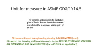
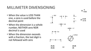
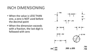
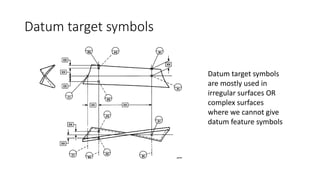
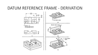
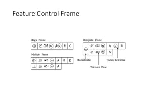
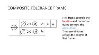
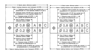
IMPORTANT POINTS IN GD&T
Sreelakshmy V.U
Unit for measure in ASME GD&T Y14.5
SI Linear unit used in engineering drawing is MILLI METER (mm).
{However, the drawing shall contain a note stating UNLESS OTHERWISE SPECIFIED,
ALL DIMENSIONS ARE IN MILLIMETERS (or in INCHES, as applicable)}
MILLIMETER DIMENSIONING
• When the value is LESS THAN
one, a zero is used before the
decimal point
• When the dimension is a whole
number, NEITHER zero NOR
decimal is used
• When the dimension exceeds
with a fraction, the last digit is
not followed with zero
INCH DIMENSIONING
• When the value is LESS THAN
one, a zero is NOT used before
the decimal point
• When the dimension exceeds
with a fraction, the last digit is
followed with zero
Reading (Counter bore, Countersunk, depth, Spot face) symbols in a drawing
VIRTUAL CONDITION & RESULTANT CONDITION
(CALCULATION)
ORDER OF PRECEDENCE OF DATUM
Datum target symbols
are mostly used in
irregular surfaces OR
complex surfaces
where we cannot give
datum feature symbols
Determining a datum feature
DATUM FEATURE - SURFACE
Datum placed on the outline of a feature
surface or on an extension line of the feature
outline, clearly separated from the
dimension line
DATUM FEATURE – AXIS
Datum placed on an extension of the
dimension line of a feature of size
Determining a datum feature - Continued
DATUM - AXIS
Datum feature symbol placed on the
outline of a cylindrical feature surface or
extension line of the feature outline
separated from the size dimension
DATUM – AXIS or CENTER PLANE
DATUM can be established if the datum
feature symbol is placed above or below
the feature control frame.
PLACING FEATURE CONTROL FRAME
1) Frame attached below the dimension (with a
leader line) pertaining to the feature
2) Frame directly attached to the feature
3) End (or) One side of the frame is attached to the
extension line from the feature, provided it is a
plane surface
4) End (or) One side of the frame is attached to the
extension of a dimension line pertaining to a
feature of size.
DATUM REFERENCE FRAME - DERIVATION
Feature Control Frame
COMPOSITE TOLERANCE FRAME
First frame controls the
location and the second
frame controls the
orientation.
The second frame
refines the control of
first frame
Two Single feature control frame
First frame controls the location
and the second frame controls the
location and orientation.
The second frame refines the
control of first frame
Additional drawings:
Thank you 
(Referred from concerned websites)

Basic Points to remember in GD&T

  • 1.
    IMPORTANT POINTS INGD&T Sreelakshmy V.U
  • 2.
    Unit for measurein ASME GD&T Y14.5 SI Linear unit used in engineering drawing is MILLI METER (mm). {However, the drawing shall contain a note stating UNLESS OTHERWISE SPECIFIED, ALL DIMENSIONS ARE IN MILLIMETERS (or in INCHES, as applicable)}
  • 3.
    MILLIMETER DIMENSIONING • Whenthe value is LESS THAN one, a zero is used before the decimal point • When the dimension is a whole number, NEITHER zero NOR decimal is used • When the dimension exceeds with a fraction, the last digit is not followed with zero
  • 4.
    INCH DIMENSIONING • Whenthe value is LESS THAN one, a zero is NOT used before the decimal point • When the dimension exceeds with a fraction, the last digit is followed with zero
  • 5.
    Reading (Counter bore,Countersunk, depth, Spot face) symbols in a drawing
  • 6.
    VIRTUAL CONDITION &RESULTANT CONDITION (CALCULATION)
  • 8.
  • 9.
    Datum target symbols Datumtarget symbols are mostly used in irregular surfaces OR complex surfaces where we cannot give datum feature symbols
  • 10.
    Determining a datumfeature DATUM FEATURE - SURFACE Datum placed on the outline of a feature surface or on an extension line of the feature outline, clearly separated from the dimension line DATUM FEATURE – AXIS Datum placed on an extension of the dimension line of a feature of size
  • 11.
    Determining a datumfeature - Continued DATUM - AXIS Datum feature symbol placed on the outline of a cylindrical feature surface or extension line of the feature outline separated from the size dimension DATUM – AXIS or CENTER PLANE DATUM can be established if the datum feature symbol is placed above or below the feature control frame.
  • 12.
    PLACING FEATURE CONTROLFRAME 1) Frame attached below the dimension (with a leader line) pertaining to the feature 2) Frame directly attached to the feature 3) End (or) One side of the frame is attached to the extension line from the feature, provided it is a plane surface 4) End (or) One side of the frame is attached to the extension of a dimension line pertaining to a feature of size.
  • 13.
  • 14.
  • 15.
    COMPOSITE TOLERANCE FRAME Firstframe controls the location and the second frame controls the orientation. The second frame refines the control of first frame
  • 17.
    Two Single featurecontrol frame First frame controls the location and the second frame controls the location and orientation. The second frame refines the control of first frame
  • 19.
  • 20.
    Thank you  (Referredfrom concerned websites)