Downloaded 484 times


The document details 14 geometric characteristics in Geometric Dimensioning and Tolerancing (GD&T) classified into five categories: form, orientation, location, profile, and run out. Each characteristic such as straightness, flatness, circularity, and others is explained regarding its definition, control requirements, and tolerance zones, highlighting their applications and modifiers. The document serves as a comprehensive guide to understanding how these controls define the allowable variation in manufactured parts.
Overview of GD&T symbols presented by Sreelakshmy V.U.
14 geometrical characteristics of GD&T are classified into five categories: Form, Orientation, Location, Profile, and Run Out.
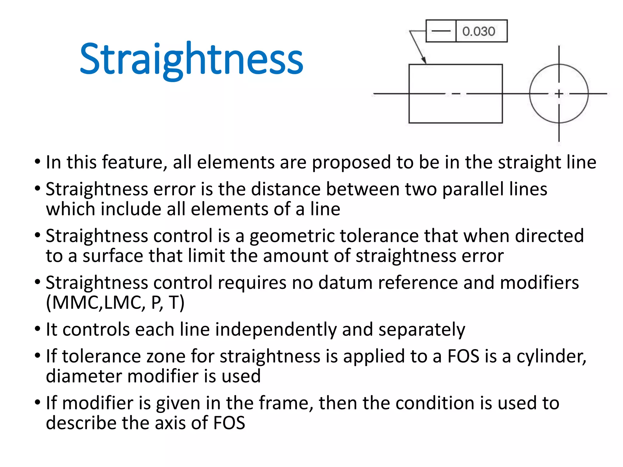
Straightness controls the line features, indicating no datum reference or modifiers required for straightness error tolerance.
Flatness limits surface features to be in one plane and requires no datum; controls the distance between parallel planes.
Circularity ensures all points of a circular feature are equidistant from an axis, controlling circularity errors without datum references.
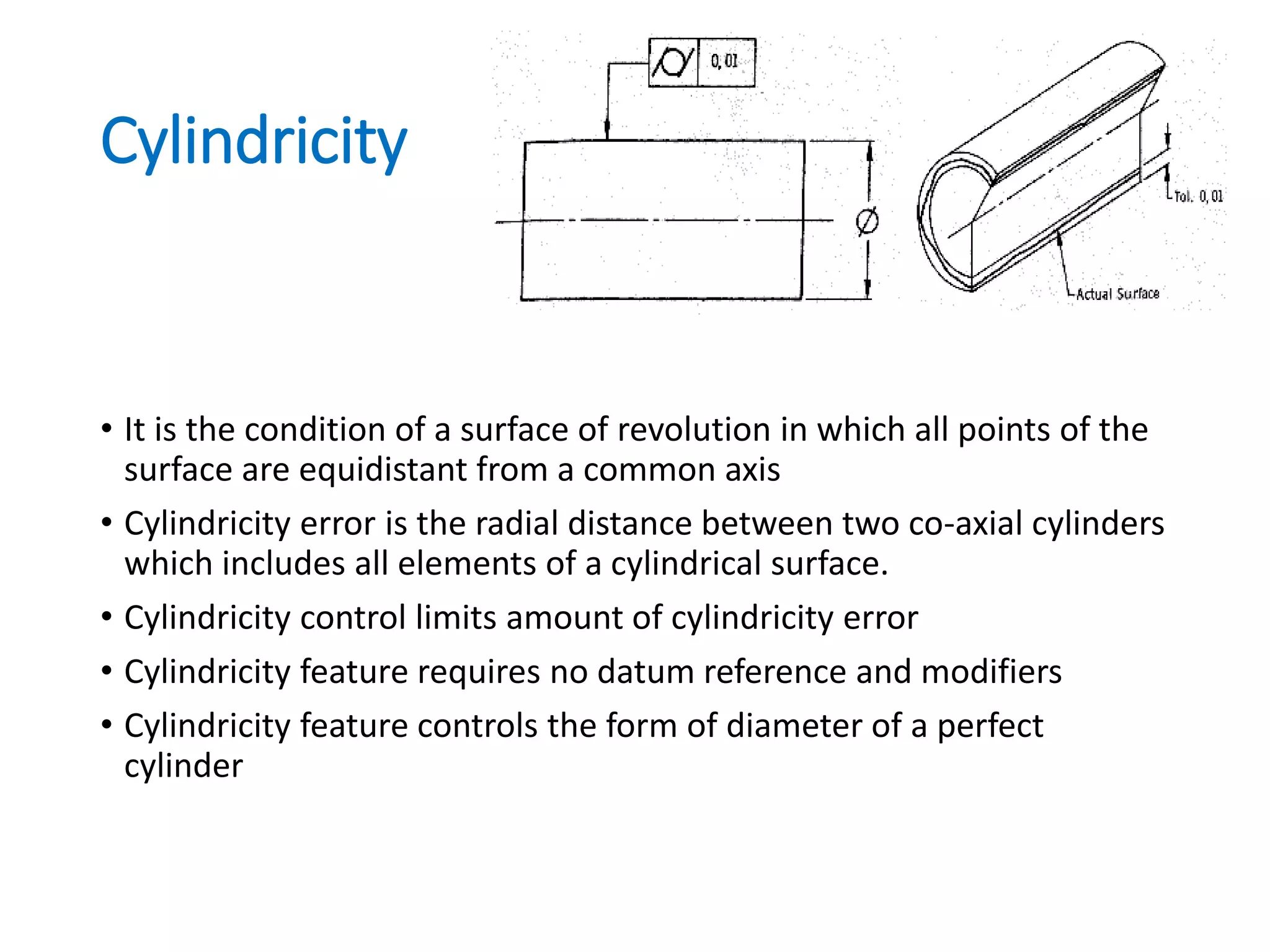
Cylindricity ensures all points on a cylindrical surface are equidistant from a common axis; requires no datum for control.
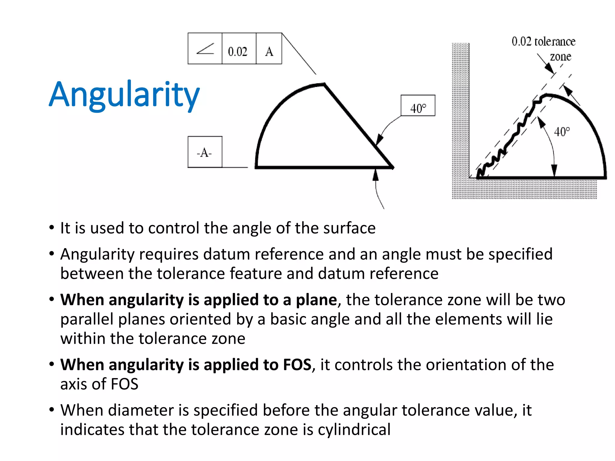
Angularity controls the angle between a surface and datum reference, with specified tolerance zones based on angular settings.
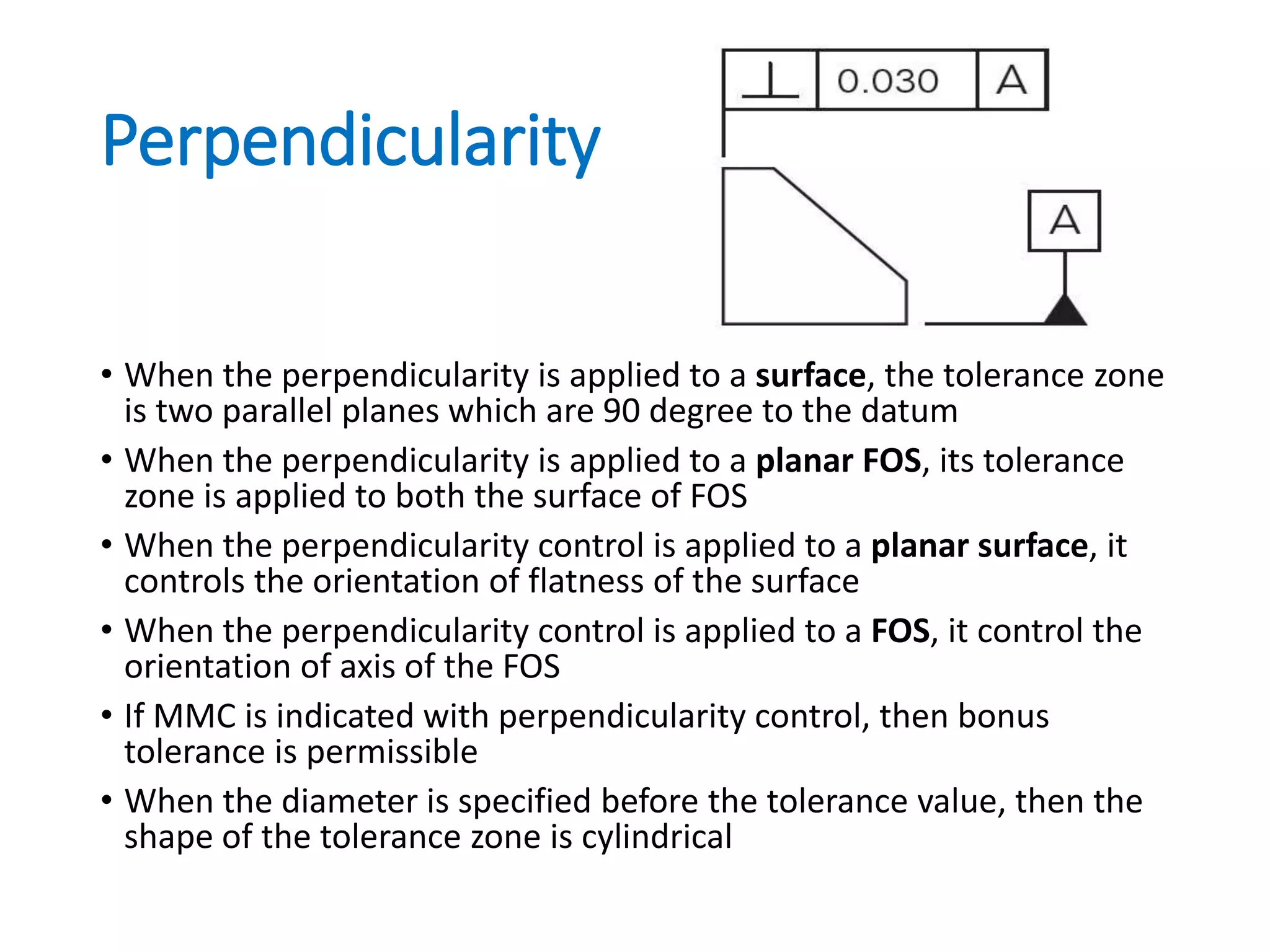
Perpendicularity applies to surfaces where the tolerance zone is defined by parallel planes oriented 90 degrees to a datum.
Parallelism defines tolerance zones for surfaces and features in relation to datum, with shapes determined based on specified diameters.
Position tolerance controls the location of features, relying on true position and requiring modifiers and datum references.
Concentricity ensures symmetrical elements relate to a datum's axis; requires datum reference and has a cylindrical tolerance zone.
Symmetry control applies to planar features with median points aligned to a datum, defining tolerance zones based on control value.
Profile of a line establishes a 2D tolerance zone controlling line elements, suitable for parts with varying cross-sections.
Profile of a surface is a 3D geometric tolerance controlling size, orientation, and form of the surface with a uniform boundary.
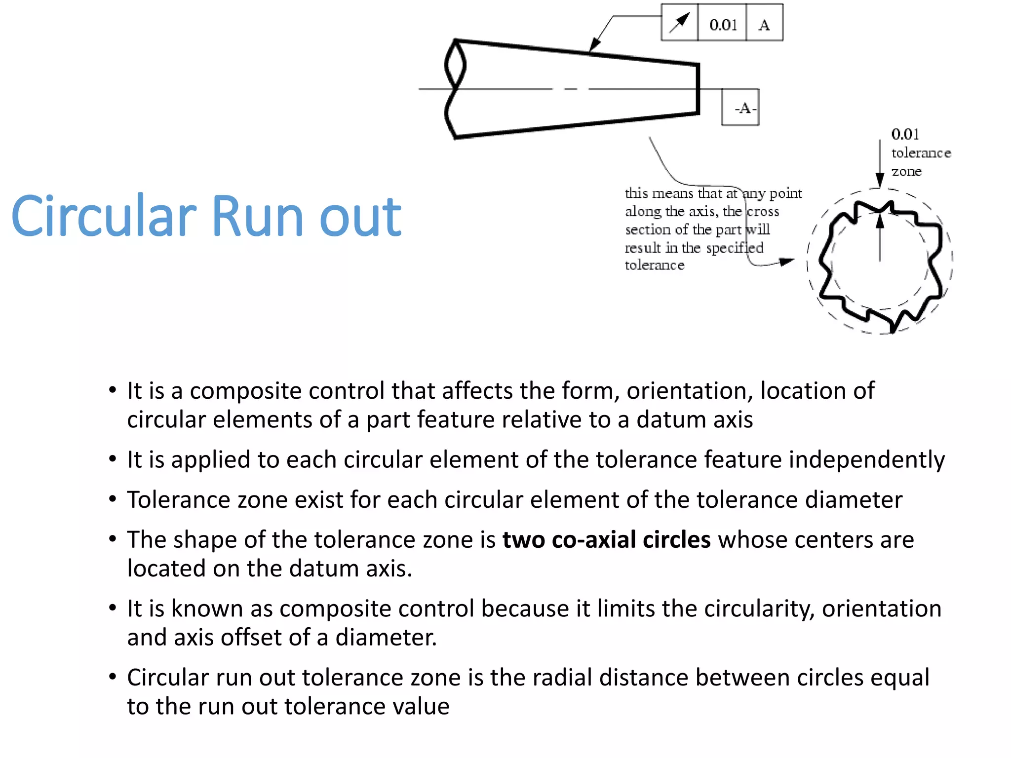
Circular run out is a composite control affecting the form and orientation of circular features, with zones defined relative to a datum.
Total run out is a comprehensive control affecting all surface elements; requires datum and defines a cylindrical tolerance zone.
Wrap-up and thank you message at the end of the presentation.


![Ppt Fits Tolerances[1]](https://cdn.slidesharecdn.com/ss_thumbnails/pptfitstolerances1-091107045206-phpapp01-thumbnail.jpg?width=640&height=640&fit=bounds)