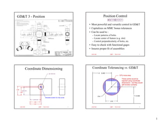
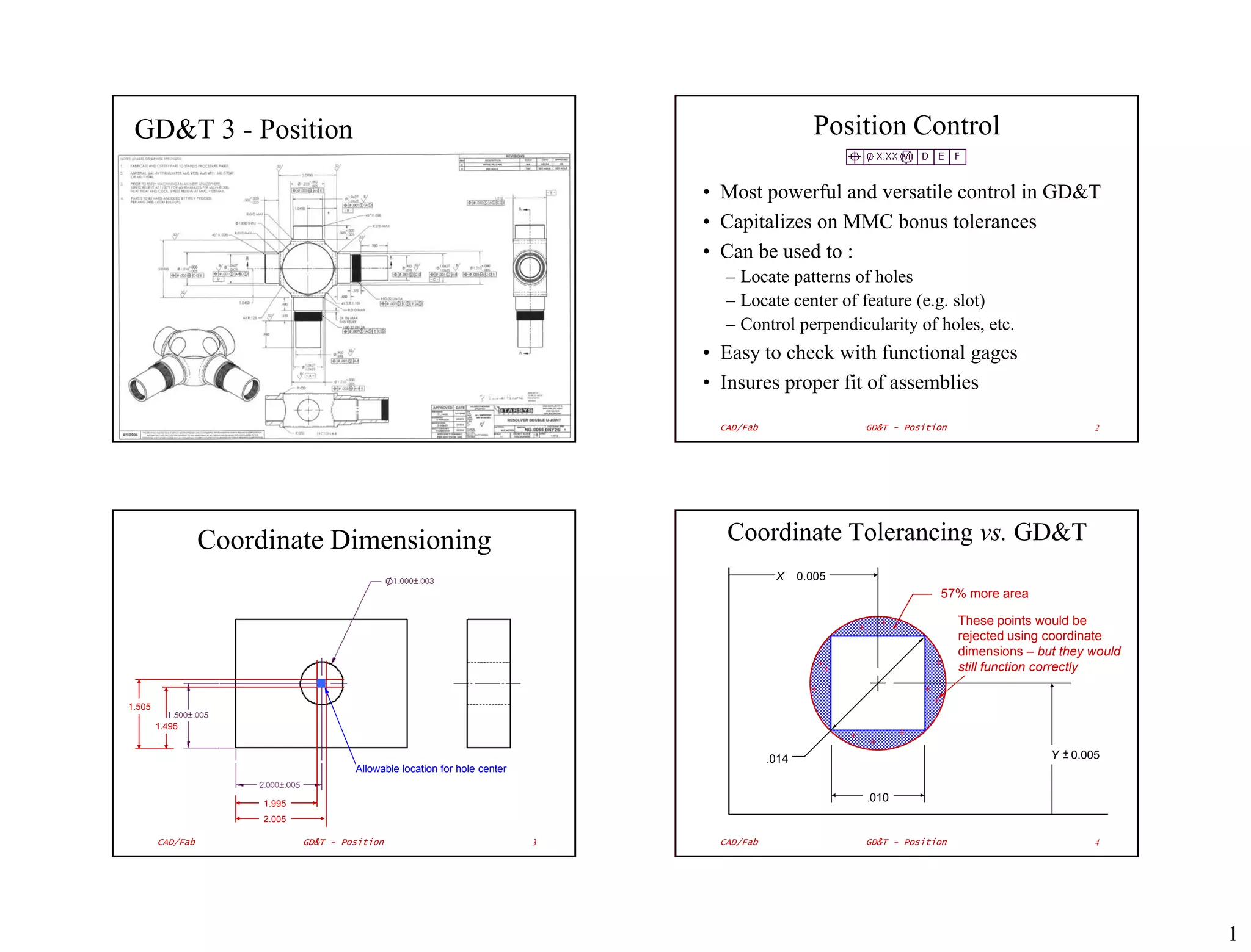
GD&T 3 - Position                                                                                    Position Control

                                                                                 • Most powerful and versatile control in GD&T
                                                                                 • Capitalizes on MMC bonus tolerances
                                                                                 • Can be used to :
                                                                                    – Locate patterns of holes
                                                                                    – Locate center of feature (e.g. slot)
                                                                                    – Control perpendicularity of holes, etc.
                                                                                 • Easy to check with functional gages
                                                                                 • Insures proper fit of assemblies

                                                                                   CAD/Fab                  GD&T - Position                          2


                  Coordinate Dimensioning                                           Coordinate Tolerancing vs. GD&T
                                                                                              X     0.005
                                                                                                                         57% more area

                                                                                                                              These points would be
                                                                                                                              rejected using coordinate
                                                                                                                              dimensions – but they would
                                                                                                                              still function correctly


1.505

        1.495


                                                                                             .014                                            Y   0.005
                                        Allowable location for hole center

                                                                                                            .010
                       1.995
                       2.005

        CAD/Fab                GD&T - Position                               3     CAD/Fab                  GD&T - Position                          4


                                                                                                                                                            1
GD&T Position Dimensioning                                           BASIC Dimension
                                              GD&T          A numerical value used to describe the theoretically
                                              control
                                              frame             exact size, profile, orientation or location of a
                                                                            feature or datum target

                                                            The associated tolerance for a BASIC dimension is
                                                                     given in the GD&T control frame
                                                                                                                Hole size
                                                                                                                parameters


                                                                                        Tolerance of location
   Basic                             Datums                                             Exact (theoretical) value
dimensions                                                                              Box indicates BASIC dimension
                                                                                        Implied tolerances do not apply!
  CAD/Fab          GD&T - Position                  5       CAD/Fab                 GD&T - Position                          6


  BASIC Dimensions and Datums                                         Orthogonal Datum Planes
                                                        Secondary Datum Plane
                                                          2 points of contact
       BASIC dimensions must relate to datums                   1 d.o.f.                               Tertiary Datum Plane
                                                                                                        1 point of contact
                                                                                                              0 d.o.f.
                                                                                                        (i.e. part is fixed)


                                                                Primary Datum Plane

                                     Why Datum D?
                                                                  3 points of contact                    “3-2-1” Rule
                                                                3 degrees of freedom
  CAD/Fab          GD&T - Position                  7       CAD/Fab                 GD&T - Position                          8


                                                                                                                                 2
How to Measure Holes                                       GO – NO GO Gages
• Diameter
  – Specified by diameter and tolerance (MMC/LMC)
  – Measure accurately with micrometer/caliper                           Allowable variation
                                                                          in hole diameter
  – Checked with GO – NO GO gages
• Position
  – Specified by GD&T frame & basic dimensions
  – Measure accurately with optical comparator          Hole Hole
                                                        LMC MMC
  – Checked with functional gages

                                                                                        GO        NO GO   Handle


 CAD/Fab          GD&T - Position                  9     CAD/Fab                GD&T - Position                    10


           GO – NO GO Gages                                         Checking Gear Hole Size

                      Gage can enter “good” hole
                      – but not past “NO GO step


 CAD/Fab          GD&T - Position                  11    CAD/Fab                GD&T - Position                    12


                                                                                                                        3
GO – NO GO Gages                                                      Gaging True Position Holes

    Go               No Go

                                        Go       No Go
                                                                                                                      Holes at MMC (12.70)
                                                                                                   26.18 max             at max distance


                                                                                                                               Centers of holes must lie
                                                                                                                               within 0.18 tolerance zone

                                                                                                    25.82 min
                         Gage tolerance –                                                                                   Gage pins
                         0.0002” – 0.00002”                                                    Holes at MMC (12.70)
                                                                                                  at min distance
                                                                                                                            dpin = 12.70 – 0.18 = 12.52
                           $36        $57
                                                                               When two holes are located at true position at MMC (min. dia.), they
                                                                               may be gaged with pins 12.52 mm in dia. located 26.00 mm apart
CAD/Fab                       GD&T - Position                          13       CAD/Fab                   GD&T - Position                               14


              Pin Gage Dimensions                                                   Datum B
                                                                                                        Pin Gage
          Part Drawing
                                                                                                                             Datum C


          Gage Drawing
                                       Pin diameter = hole diameter @ MMC –
                                                GD&T position tolerance                                                                        Datum A
                                          i.e. dia = 12.70 – 0.18 = 12.52 mm


                         Pin location specified by
                         BASIC dimensions
CAD/Fab                       GD&T - Position                          15       CAD/Fab                   GD&T - Position                               16


                                                                                                                                                             4
Position Lab                                                                Combined Datums
                      Snowboard Binding                                     A gear will be
                                                                            pressed onto
                                                                            a gear shaft
                                                                            which runs in
                                                                            ball bearings
                                                                            as shown.
                                                                            Identify
                                                                            datums on
                                                                            the drawing
                                                                            of the shaft to
                                                        Perfect part        ensure
                                                                            proper
                                                                            operation of
                                                                            the gear shaft                  C
                                                                            assembly.
                                                                                                                               Combined
                                                                                                                               datum –
                                                                                                                               centerline
                                                                                                                               joining A & B
                                                          Reject!                              A                           B


   CAD/Fab                  GD&T - Position                            17            CAD/Fab             GD&T - Position              18


             Checking Shaft Runout                                                                 Combined Datums
2. Shaft rotated in
                                              3. Dial indicator measures
    V-blocks
                                               tip movement accurately                         B


                                                                                 D                   C


                                                                                               A


         1. V-blocks center shaft at each end


   CAD/Fab                  GD&T - Position                            19            CAD/Fab             GD&T - Position              20


                                                                                                                                               5

Gd&t position

  • 1.
    GD&T 3 -Position Position Control • Most powerful and versatile control in GD&T • Capitalizes on MMC bonus tolerances • Can be used to : – Locate patterns of holes – Locate center of feature (e.g. slot) – Control perpendicularity of holes, etc. • Easy to check with functional gages • Insures proper fit of assemblies CAD/Fab GD&T - Position 2 Coordinate Dimensioning Coordinate Tolerancing vs. GD&T X 0.005 57% more area These points would be rejected using coordinate dimensions – but they would still function correctly 1.505 1.495 .014 Y 0.005 Allowable location for hole center .010 1.995 2.005 CAD/Fab GD&T - Position 3 CAD/Fab GD&T - Position 4 1
  • 2.
    GD&T Position Dimensioning BASIC Dimension GD&T A numerical value used to describe the theoretically control frame exact size, profile, orientation or location of a feature or datum target The associated tolerance for a BASIC dimension is given in the GD&T control frame Hole size parameters Tolerance of location Basic Datums Exact (theoretical) value dimensions Box indicates BASIC dimension Implied tolerances do not apply! CAD/Fab GD&T - Position 5 CAD/Fab GD&T - Position 6 BASIC Dimensions and Datums Orthogonal Datum Planes Secondary Datum Plane 2 points of contact BASIC dimensions must relate to datums 1 d.o.f. Tertiary Datum Plane 1 point of contact 0 d.o.f. (i.e. part is fixed) Primary Datum Plane Why Datum D? 3 points of contact “3-2-1” Rule 3 degrees of freedom CAD/Fab GD&T - Position 7 CAD/Fab GD&T - Position 8 2
  • 3.
    How to MeasureHoles GO – NO GO Gages • Diameter – Specified by diameter and tolerance (MMC/LMC) – Measure accurately with micrometer/caliper Allowable variation in hole diameter – Checked with GO – NO GO gages • Position – Specified by GD&T frame & basic dimensions – Measure accurately with optical comparator Hole Hole LMC MMC – Checked with functional gages GO NO GO Handle CAD/Fab GD&T - Position 9 CAD/Fab GD&T - Position 10 GO – NO GO Gages Checking Gear Hole Size Gage can enter “good” hole – but not past “NO GO step CAD/Fab GD&T - Position 11 CAD/Fab GD&T - Position 12 3
  • 4.
    GO – NOGO Gages Gaging True Position Holes Go No Go Go No Go Holes at MMC (12.70) 26.18 max at max distance Centers of holes must lie within 0.18 tolerance zone 25.82 min Gage tolerance – Gage pins 0.0002” – 0.00002” Holes at MMC (12.70) at min distance dpin = 12.70 – 0.18 = 12.52 $36 $57 When two holes are located at true position at MMC (min. dia.), they may be gaged with pins 12.52 mm in dia. located 26.00 mm apart CAD/Fab GD&T - Position 13 CAD/Fab GD&T - Position 14 Pin Gage Dimensions Datum B Pin Gage Part Drawing Datum C Gage Drawing Pin diameter = hole diameter @ MMC – GD&T position tolerance Datum A i.e. dia = 12.70 – 0.18 = 12.52 mm Pin location specified by BASIC dimensions CAD/Fab GD&T - Position 15 CAD/Fab GD&T - Position 16 4
  • 5.
    Position Lab Combined Datums Snowboard Binding A gear will be pressed onto a gear shaft which runs in ball bearings as shown. Identify datums on the drawing of the shaft to Perfect part ensure proper operation of the gear shaft C assembly. Combined datum – centerline joining A & B Reject! A B CAD/Fab GD&T - Position 17 CAD/Fab GD&T - Position 18 Checking Shaft Runout Combined Datums 2. Shaft rotated in 3. Dial indicator measures V-blocks tip movement accurately B D C A 1. V-blocks center shaft at each end CAD/Fab GD&T - Position 19 CAD/Fab GD&T - Position 20 5