Download to read offline

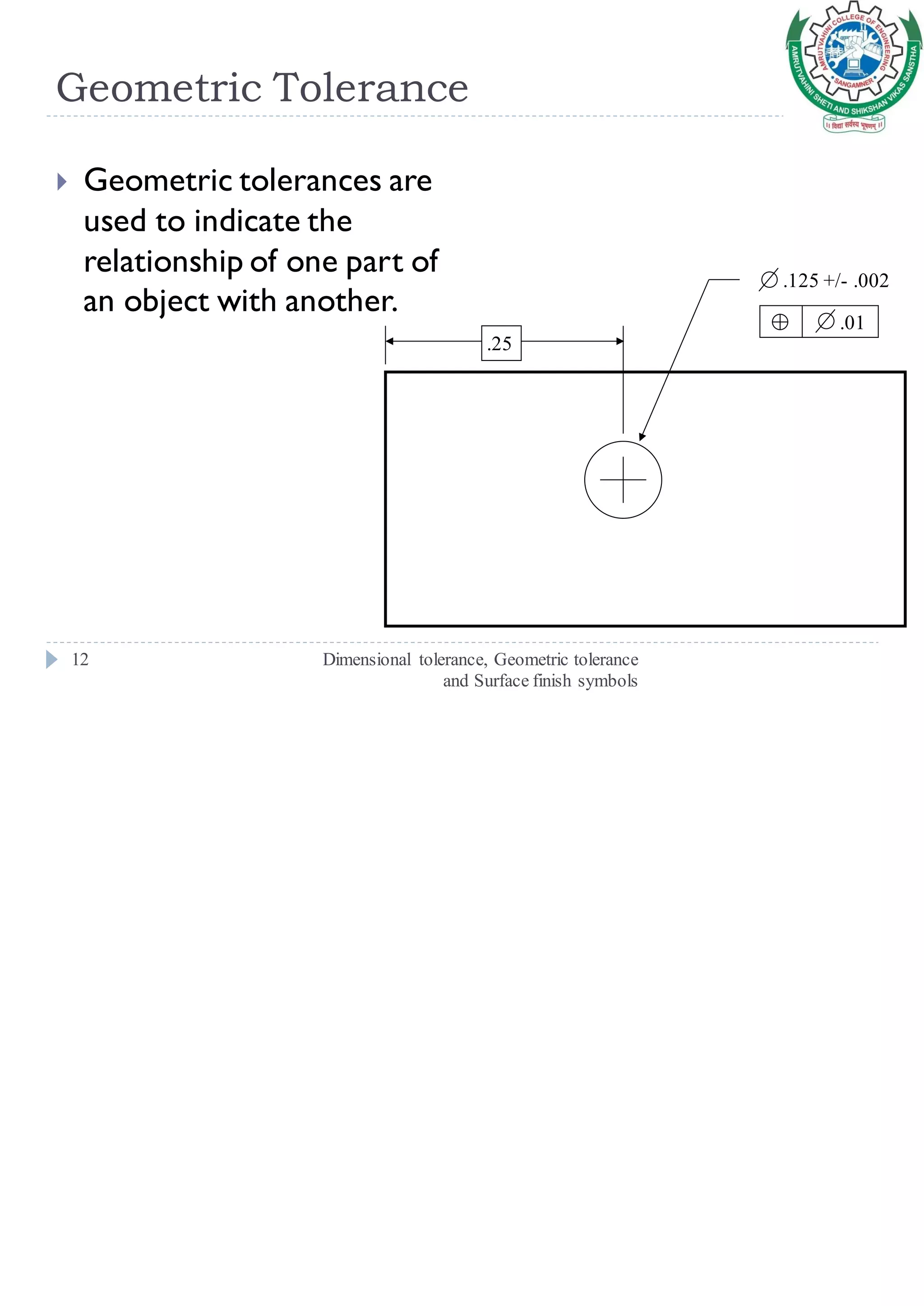
![Unilateral Tolerance
Dimensional tolerance, Geometric tolerance
and Surface finish symbols
9
Variation Variation from
the specified dimension
is permitted in only one
direction
Either positive or
negative, but not both
[5]](https://image.slidesharecdn.com/gdt-190718132910/75/Geometric-Dimensioning-and-Tolerancing-9-2048.jpg)
![Bilateral Tolerance
Dimensional tolerance, Geometric tolerance
and Surface finish symbols
10
Variation is permitted in
both positive and
negative directions from
the nominal dimension
Possible for a bilateral
tolerance to be
unbalanced.
Ex:2.500 +0.010,-0.005
[5]](https://image.slidesharecdn.com/gdt-190718132910/75/Geometric-Dimensioning-and-Tolerancing-10-2048.jpg)
![Compound tolerance
Dimensional tolerance, Geometric tolerance
and Surface finish symbols
11
When tolerance is
determined by established
tolerances on more than
one dimension,it is known
as compound tolerance.
Example tolerance R
[5]](https://image.slidesharecdn.com/gdt-190718132910/75/Geometric-Dimensioning-and-Tolerancing-11-2048.jpg)
![Datum Reference Frame (DRF):
Dimensional tolerance, Geometric tolerance
and Surface finish symbols
13
Primary Features & Datum
Secondary Features & Datum
Tertiary Features & Datum
[1]](https://image.slidesharecdn.com/gdt-190718132910/75/Geometric-Dimensioning-and-Tolerancing-13-2048.jpg)
![Datum Feature vs Datum Plane:
Dimensional tolerance, Geometric tolerance
and Surface finish symbols
14
The datum features are
the features (surfaces) on
the part that will be
contacted by the datum
simulators.
The symbol is a capital
letter (except I,O,and Q)
in a box such as A
[1]](https://image.slidesharecdn.com/gdt-190718132910/75/Geometric-Dimensioning-and-Tolerancing-14-2048.jpg)
![Datum Plane vs Datum Axis
Dimensional tolerance, Geometric tolerance
and Surface finish symbols
15
A datum plane is the datum simulator such as a
surface plate.
A datum axis is also the axis of a datum simulator
such as a three (3) jaw chuck or an expandable collt.
[1]](https://image.slidesharecdn.com/gdt-190718132910/75/Geometric-Dimensioning-and-Tolerancing-15-2048.jpg)
![Feature Control Frame:
Dimensional tolerance, Geometric tolerance
and Surface finish symbols
16
[4]](https://image.slidesharecdn.com/gdt-190718132910/75/Geometric-Dimensioning-and-Tolerancing-16-2048.jpg)
![GD&T Symbols / Meanings
Dimensional tolerance, Geometric tolerance
and Surface finish symbols
17
[1]](https://image.slidesharecdn.com/gdt-190718132910/75/Geometric-Dimensioning-and-Tolerancing-17-2048.jpg)

![Position Tolerance
Dimensional tolerance, Geometric tolerance
and Surface finish symbols
19
Positional tolerances are probably
used more than any other
geometric control.
It is used to locate features of size
from datum planes such as a hole or
keyway and used to locate features
coaxial to a datum axis.
which is shown in a box
[1]](https://image.slidesharecdn.com/gdt-190718132910/75/Geometric-Dimensioning-and-Tolerancing-19-2048.jpg)
![Concentricity & Symmetry Tolerances
Dimensional tolerance, Geometric tolerance
and Surface finish symbols
20
Concentricity is applied to circular.
whereas symmetry is applied to non circular
features.
[1]](https://image.slidesharecdn.com/gdt-190718132910/75/Geometric-Dimensioning-and-Tolerancing-20-2048.jpg)
![Profile Tolerance
Dimensional tolerance, Geometric tolerance
and Surface finish symbols
21
Profile tolerances can control the location, orientation,
and form of a feature that has no size (surface).
[1]](https://image.slidesharecdn.com/gdt-190718132910/75/Geometric-Dimensioning-and-Tolerancing-21-2048.jpg)
![Run Out Tolerances
Dimensional tolerance, Geometric tolerance
and Surface finish symbols
22
Run out tolerances control the relationship of a feature
relative to a datum axis established from one (1) diameter
or two (2) diameters separated axially.
[1]](https://image.slidesharecdn.com/gdt-190718132910/75/Geometric-Dimensioning-and-Tolerancing-22-2048.jpg)
![Orientation Tolerances
Dimensional tolerance, Geometric tolerance
and Surface finish symbols
23
Perpendicularity symbol is ⊥
Parallelism symbol is ⁄⁄
[1]](https://image.slidesharecdn.com/gdt-190718132910/75/Geometric-Dimensioning-and-Tolerancing-23-2048.jpg)
![Form Tolerances
Dimensional tolerance, Geometric tolerance
and Surface finish symbols
24
Straightness
Flatness
Circularity (Roundness)
Cylindricity
[1]](https://image.slidesharecdn.com/gdt-190718132910/75/Geometric-Dimensioning-and-Tolerancing-24-2048.jpg)
![Surface Roughness Equation
Dimensional tolerance, Geometric tolerance
and Surface finish symbols
25
Arithmetic average (AA)
where Ra = average
roughness
y = vertical deviation
from nominal surface
Lm = specified
distance over which the
surface deviations are
measured.
dx
L
y
R
mL
m
a ∫
0
=
[5]](https://image.slidesharecdn.com/gdt-190718132910/75/Geometric-Dimensioning-and-Tolerancing-25-2048.jpg)
![Lay Symbols
Dimensional tolerance, Geometric tolerance
and Surface finish symbols
26
[2]](https://image.slidesharecdn.com/gdt-190718132910/75/Geometric-Dimensioning-and-Tolerancing-26-2048.jpg)
![Surface Roughness Specification
Dimensional tolerance, Geometric tolerance
and Surface finish symbols
27
[3]](https://image.slidesharecdn.com/gdt-190718132910/75/Geometric-Dimensioning-and-Tolerancing-27-2048.jpg)
![Case Study
Dimensional tolerance, Geometric tolerance
and Surface finish symbols
29
[2]](https://image.slidesharecdn.com/gdt-190718132910/75/Geometric-Dimensioning-and-Tolerancing-29-2048.jpg)
![Referances
Dimensional tolerance, Geometric tolerance
and Surface finish symbols
30
NADCA Product Specification Standards for Die Castings / 2006 [1]
GD&TWorking through the Misconceptions
https://i1.wp.com/advantagegdt.net/wp-content/uploads/2014/03/piston_Page_2-
8x6.png [2]
Understanding surface roughness symbols
https://www.keyence.com/ss/products/microscope/roughness/line/roughness-
symbols.jsp [3]
9/4/2014 Argonne National Laboratory / Daniel Pasholk
https://www.aps.anl.gov/files/APS-Uploads/DD/Procedurals/Datums_GDT.pptx [4]
GD&T PPTX http://www.itt.3d-me-ds.com/ppt/Week1_ GDT.ppt [5]](https://image.slidesharecdn.com/gdt-190718132910/75/Geometric-Dimensioning-and-Tolerancing-30-2048.jpg)

The document provides a comprehensive overview of Geometric Dimensioning and Tolerancing (GD&T), including its history, types of tolerances, and symbols. It outlines the importance of GD&T in ensuring clear communication between manufacturers and designers and simplifies the inspection process. Key topics include dimensional tolerance, geometric tolerance, surface finish symbols, and specific case studies related to GD&T applications.