Mechanical production of stirling Engine
•
1 like•214 views

Mechanical production of stirling Engine

Recommended
More Related Content
What's hot
What's hot (18)
Viewers also liked
Viewers also liked (20)
Similar to Mechanical production of stirling Engine
Similar to Mechanical production of stirling Engine (20)
More from Kum Visal
More from Kum Visal (20)
Recently uploaded
Recently uploaded (20)
Mechanical production of stirling Engine
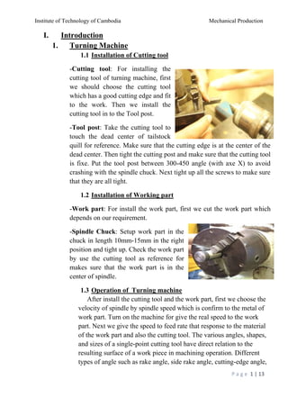
- 1. Institute of Technology of Cambodia Mechanical Production P a g e 1 | 13 I. Introduction 1. Turning Machine 1.1 Installation of Cutting tool -Cutting tool: For installing the cutting tool of turning machine, first we should choose the cutting tool which has a good cutting edge and fit to the work. Then we install the cutting tool in to the Tool post. -Tool post: Take the cutting tool to touch the dead center of tailstock quill for reference. Make sure that the cutting edge is at the center of the dead center. Then tight the cutting post and make sure that the cutting tool is fixe. Put the tool post between 300-450 angle (with axe X) to avoid crashing with the spindle chuck. Next tight up all the screws to make sure that they are all tight. 1.2 Installation of Working part -Work part: For install the work part, first we cut the work part which depends on our requirement. -Spindle Chuck: Setup work part in the chuck in length 10mm-15mm in the right position and tight up. Check the work part by use the cutting tool as reference for makes sure that the work part is in the center of spindle. 1.3 Operation of Turning machine After install the cutting tool and the work part, first we choose the velocity of spindle by spindle speed which is confirm to the metal of work part. Turn on the machine for give the real speed to the work part. Next we give the speed to feed rate that response to the material of the work part and also the cutting tool. The various angles, shapes, and sizes of a single-point cutting tool have direct relation to the resulting surface of a work piece in machining operation. Different types of angle such as rake angle, side rake angle, cutting-edge angle,
- 2. Institute of Technology of Cambodia Mechanical Production P a g e 2 | 13 relief angle, nose radius exist and may be different with respect to the work piece. Also, there are many shapes of single- point cutting tool, such as – shaped and square. Usually, a special tool holder is used to hold the cutting tool firmly during operation. The relative forces in a turning operation are important in the design of machine tools. The machine tool and its component must be able to withstand these forces without causing significant deflection, vibration, or chatter during the operation. There are three principal forces during a turning process. The cutting or tangential force acts downward on the tool tip allowing deflection of the work piece upward. It supplies the energy required for the cutting operation. The specific cutting force required to cut the material is called specific cutting force. Cutting force is depends on the material. The axial or feed force acts in the longitudinal direction. It is also called the feed force because it is in the feed direction of the tool. This force tends to push the tool away from the chuck. The radial or thrust force acts in the radial direction and tends to push the tool away from the work part. Speeds and feed for turning are chosen based on cutter material, Work piece material, setup rigidity, machine tool rigidity and spindle power, coolant choice, and other factors. The distance the tool advances into the material in one revolution is called feed. It is specified as mm per revolution (mm/rev). 2. Milling Machine 2.1 Installation of Cutting tool Firstly, turn off the machine before install the cutting tool. Then, screw the bolt on the top of machine and hold the head of machine by a fabric or piece of cloth to avoid rotation of the knife. We use wrench to screw the bolt and if the bolt is too tight, we can use aluminum hammer to hit the wrench for loosen the bolt easily.
- 3. Institute of Technology of Cambodia Mechanical Production P a g e 3 | 13 Check the knife if it has metal pieces stick on it or not. You have to clean it and apply the lubricant every time you use it. Take out the old cutting tool and put your new knife to the hole properly to avoid cutting your hand or finger. Finally, we screw the bolt tightly. 2.2 Installation of Working part First of all, you need to have two steels rectangular-shaped for deposit the work part. After put these two steels below the work part, you have to use axis Y (move toward and backward) or the table cross hand wheel to make the work part stable during work. Use steel perpendicular ruler to measure the work part and make sure that it is perpendicular to the plan. Then, use axis X (move to the left and to the right) or table feed hand wheel and axis Z (move up and down) or knee elevating handle to adjust the work part close to the cutting tool. 2.3 Operation of Milling machine Check out the cutting tool and the work part again if they are installed incorrectly. If not, it causes some problem such as the knife breaks, the work part has been damaged…etc. Set the scale (mm) on the wheel of axis X,Y,Z for the size we want to cut on the work part’s surface (0.1mm; 0.2mm;…). When you already adjusted the scale on axis X and Z, you have to lock these two tables by the lock handle of each axis. This can protect from sliding of table work. Adjust the speed of the knife and the speed of tables.
- 4. Institute of Technology of Cambodia Mechanical Production P a g e 4 | 13 Check the water. If the machine runs out the water, put the water in and press the green button. Turn on the water, set the faucet near the knife (not too close). In front of the machine, on the bottom part, there are two buttons “Red Button” and “Blue Button”. When we start our operation, we just press the blue button. And if the machine has problem or you want to stop the process, we just press the red button. After pressed the blue button, rotate the wheel of axis X to push the work part near the cutting tool. Moreover, just spin the table feed hand wheel slowly to move left or right for cut the surface of work part. To protect yourself especially your eyes from the splash of hot metal pieces during cutting, you should wear safety goggles. In the conclusion, when the work part is finished, we press the red button. 3. Drilling Machine 3.2 Installation of Cutting tool First, we should choose the twist drill which has a good drilling edge and fit to the work (starting from small to big). Then we install the twist drill into the drill chuck. Then, take the twist drill tang to touch the dead center of drill chuck slot for reference. Make sure that the twist drill tang is at the center of the dead center. Then tight the twist drill and make sure that the twist drill is fixe. Next tight up all the screws to make sure that they are all tight. 3.2 Installation of Working part First of all, you need to have two steels rectangular-shaped for deposit the work part. After put these two steels below the work part, you have to use axis Y (move toward and backward) or the table cross hand wheel to make the work part stable during work. Use steel perpendicular ruler to measure the work part and make sure that it is perpendicular to the plan.
- 5. Institute of Technology of Cambodia Mechanical Production P a g e 5 | 13 Then, use axis X (move to the left and to the right) or table feed hand wheel and axis Z (move up and down) or knee elevating handle to adjust the work part close to the cutting tool. Use feed hand to handle for feed and during drilling hand it down and up often to avoid the twist drill broken. 3.3 Operation of Drilling machine Check out the twist drill and the work part again if they are installed incorrectly. If not, it causes some problem such as the knife breaks, the work part has been damaged…etc. Adjust the speed of the knife Move the machine vice that is equipped with jaws which clamps the work piece to where you want the drilling machine do on your work steel. The vice is bolted to the drilling table and you can swivel through 360° on a horizontal plane. Ensure for the cutting tools running straight before starting the operation and spin the hand feed up and down to make the twist drill in the spindle cut your steel. Avoid loose clothing and protect the eyes.
- 6. Institute of Technology of Cambodia Mechanical Production P a g e 6 | 13 II. Operation in Laboratory 1. Power Piston Cylinder In this work part we have to use cutting tool machine, turning machine, drilling machine to process it. First, we cut metal for our operation with length 40 mm with cutting tool machine (include 15mm for chuck) Second, we take our piece of metal to the chuck and start turning machine to get the result with diameter Ø 29 mm. Third, we start turning process again with depth 11 mm and length 18 mm Fourth, Drilling process with diameter Ø 13 mm Threading 4 through holds.
- 7. Institute of Technology of Cambodia Mechanical Production P a g e 7 | 13 2. Displacer Cylinder In this work piece we have to use cutting tool machine, turning machine, drilling machine to process it. First, we cut metal for our operation with length 49 mm with cutting tool machine (include 15mm for chuck) Second, we take our piece of metal to the chuck and start turning machine to get the result with diameter Ø 29 mm. Third, we start turning process again with depth 13 mm and length 28 mm Fourth, Drilling process with diameter Ø 14 mm length 26 mm Threading 4 through holds.
- 8. Institute of Technology of Cambodia Mechanical Production P a g e 8 | 13 3. Displacer Piston In this work part we need to process in cutting tool machine, turning machine, drilling machine. First, we cut metal for our operation with length 82 mm with cutting tool machine (include 15mm for chuck). Second, sawing Third, drilling process with diameter M 3. 4. Power Piston
- 9. Institute of Technology of Cambodia Mechanical Production P a g e 9 | 13 In this work part we need to process in cutting tool machine, turning machine, drilling machine. First, we cut metal for our operation with length 33 mm with cutting tool machine (include 15mm for chuck). Second, sawing Third, drilling process with diameter M 3. 5. Flywheel In this work part we need to process in cutting tool machine, turning machine, drilling machine.
- 10. Institute of Technology of Cambodia Mechanical Production P a g e 10 | 13 We need to take the cylinder that has diameter D= 27 mm and length L= 35 mm, we need 4 cylinder. Practice: Turning (facing, cut off, drilling) and Drilling (1 through hold). 6. UPPER BASE We need to take it that has length L= 74 mm, W= 34 mm, H= 12 mm Practice: Drilling (12 through holds, 1 blind hold) and Milling (facing)
- 11. Institute of Technology of Cambodia Mechanical Production P a g e 11 | 13 7. Body We need to take the body that has L= 124 mm, W= 34 mm, H= 12 mm, N= 2. Practice: Threading (4 blind holds, 1 through hold) and Milling. 8. Base
- 12. Institute of Technology of Cambodia Mechanical Production P a g e 12 | 13 We need to take the base that has L= 100 mm, W= 69 mm, H= 12 mm, N= 2. Practice: Drilling (2 through holds) and Milling. 9. Power Piston Connection Rod and Displacer Connection Rod We need to take the rod that has L= 58 mm, W= 10 mm, H= 2 mm, N= 4. Practice: Drilling (2 through holds) and Sawing.
- 13. Institute of Technology of Cambodia Mechanical Production P a g e 13 | 13 III. Conclusion After finish the work, we should remove some tools such as cutting tool, wrench, steel ruler, aluminum hammer and other tools in to the place origin and clean up all the metal pieces and the water in the machine by using brush and fabric. Clean the surface around the machine and lubricate some parts in the machine to make it clean and available for the next use.