Downloaded 2,143 times
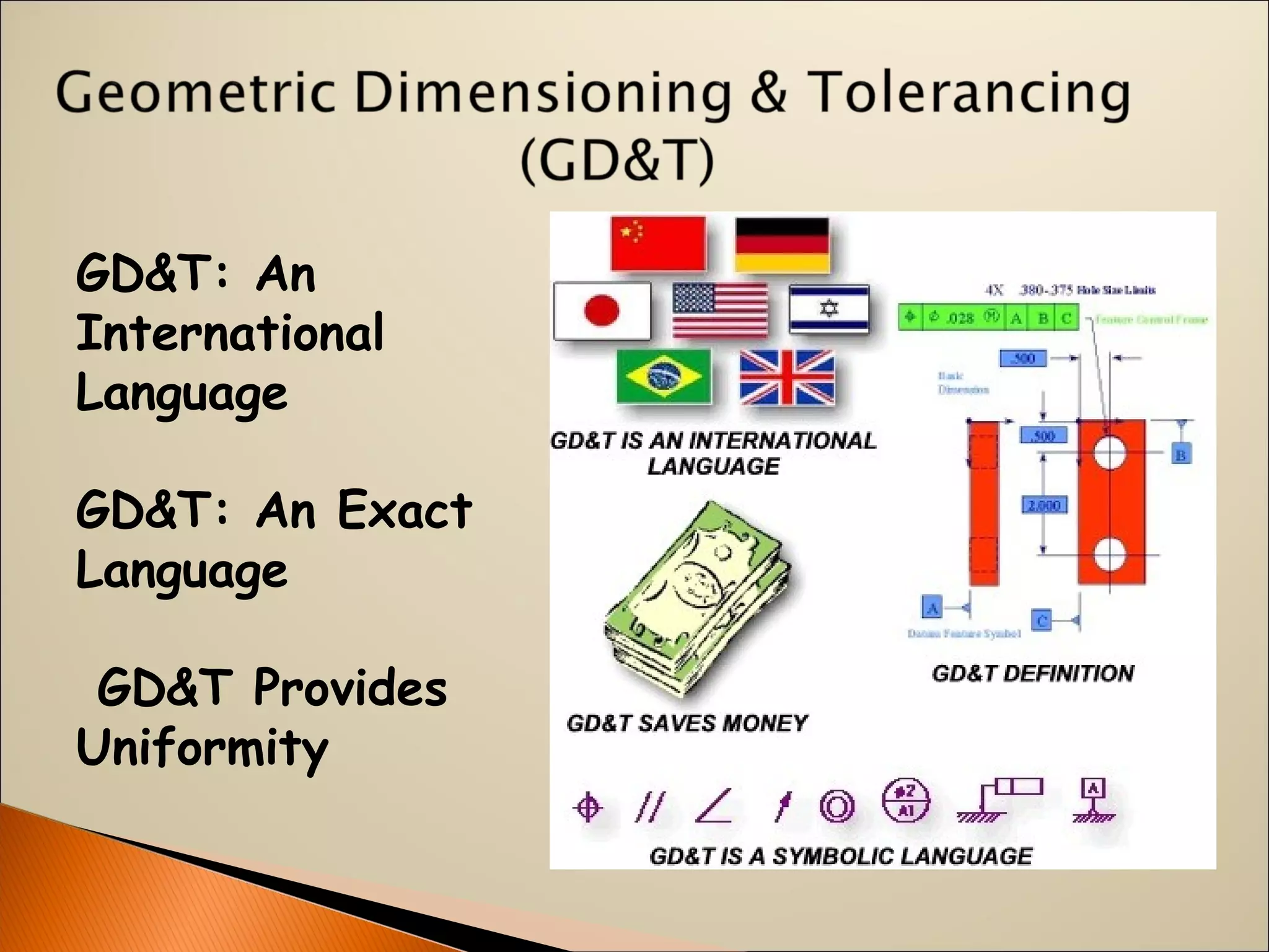

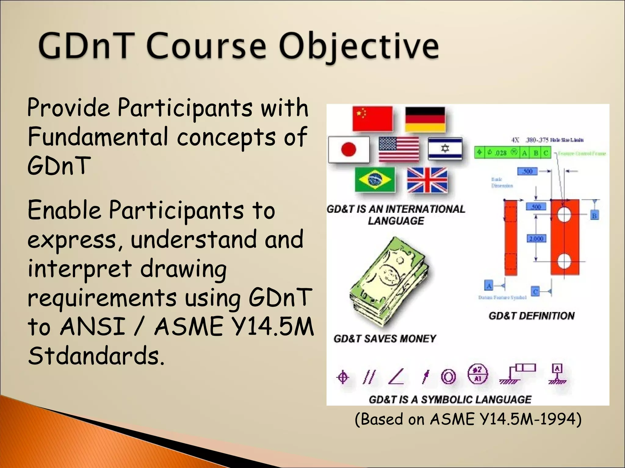
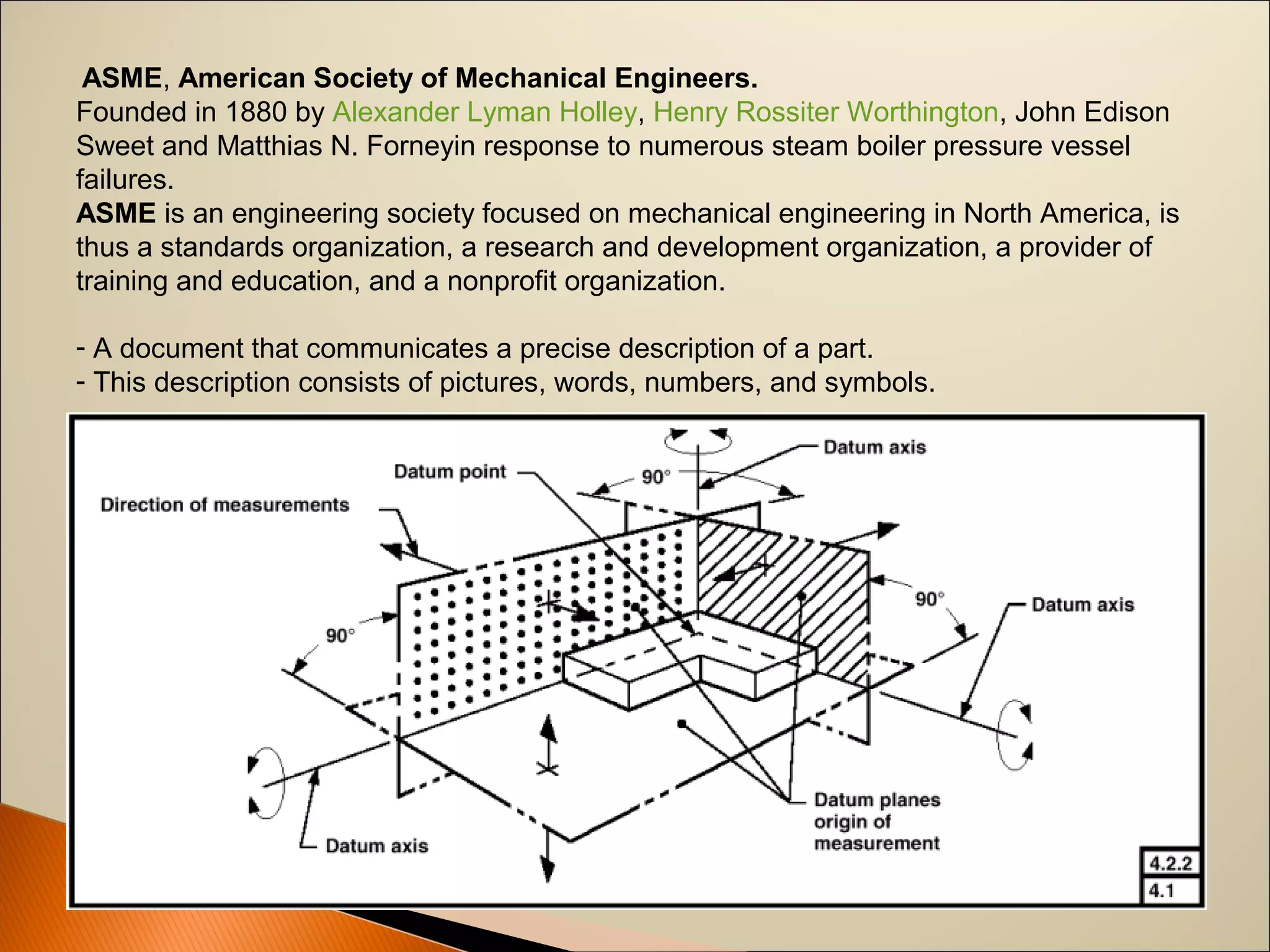
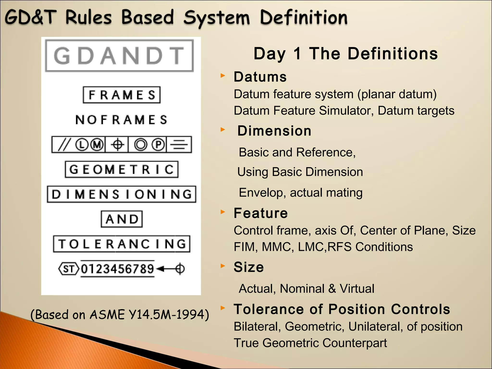
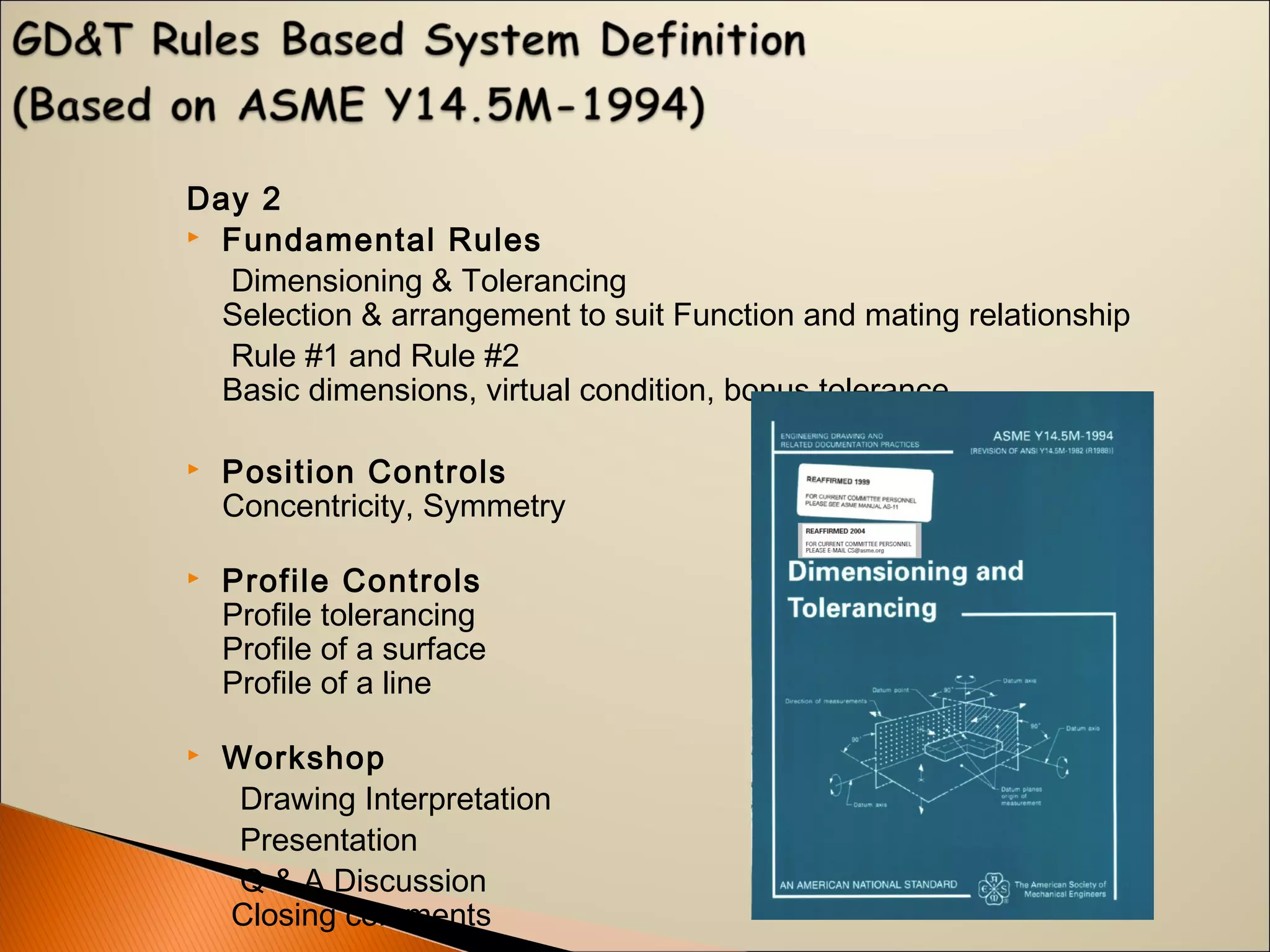


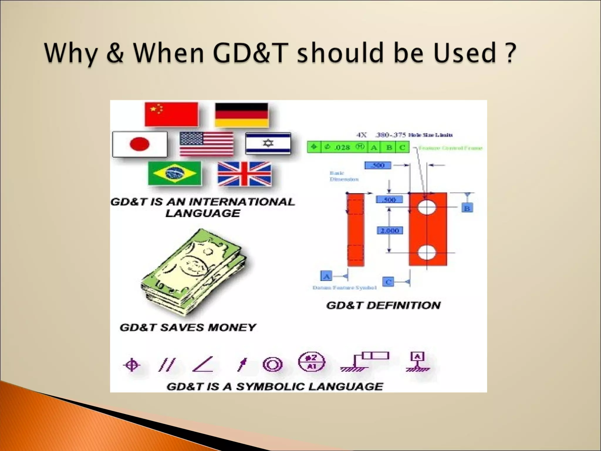
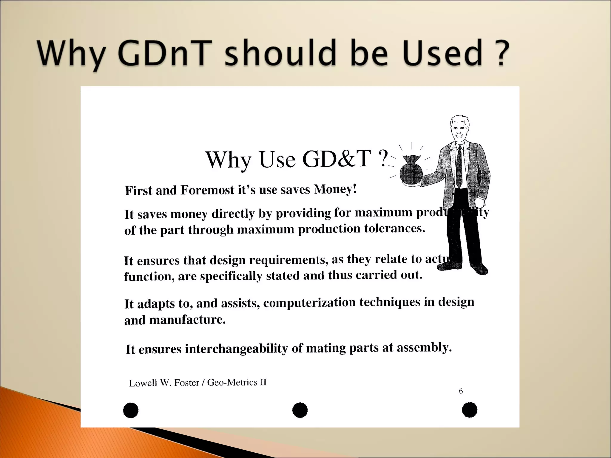


The document discusses geometric dimensioning and tolerancing (GD&T), an international language for accurately describing part specifications in engineering drawings. It outlines fundamental concepts, symbols, and rules used to communicate size, form, and tolerances, aimed at enhancing design clarity and manufacturing precision. Additionally, it highlights the American Society of Mechanical Engineers (ASME) standards that govern GD&T practices.