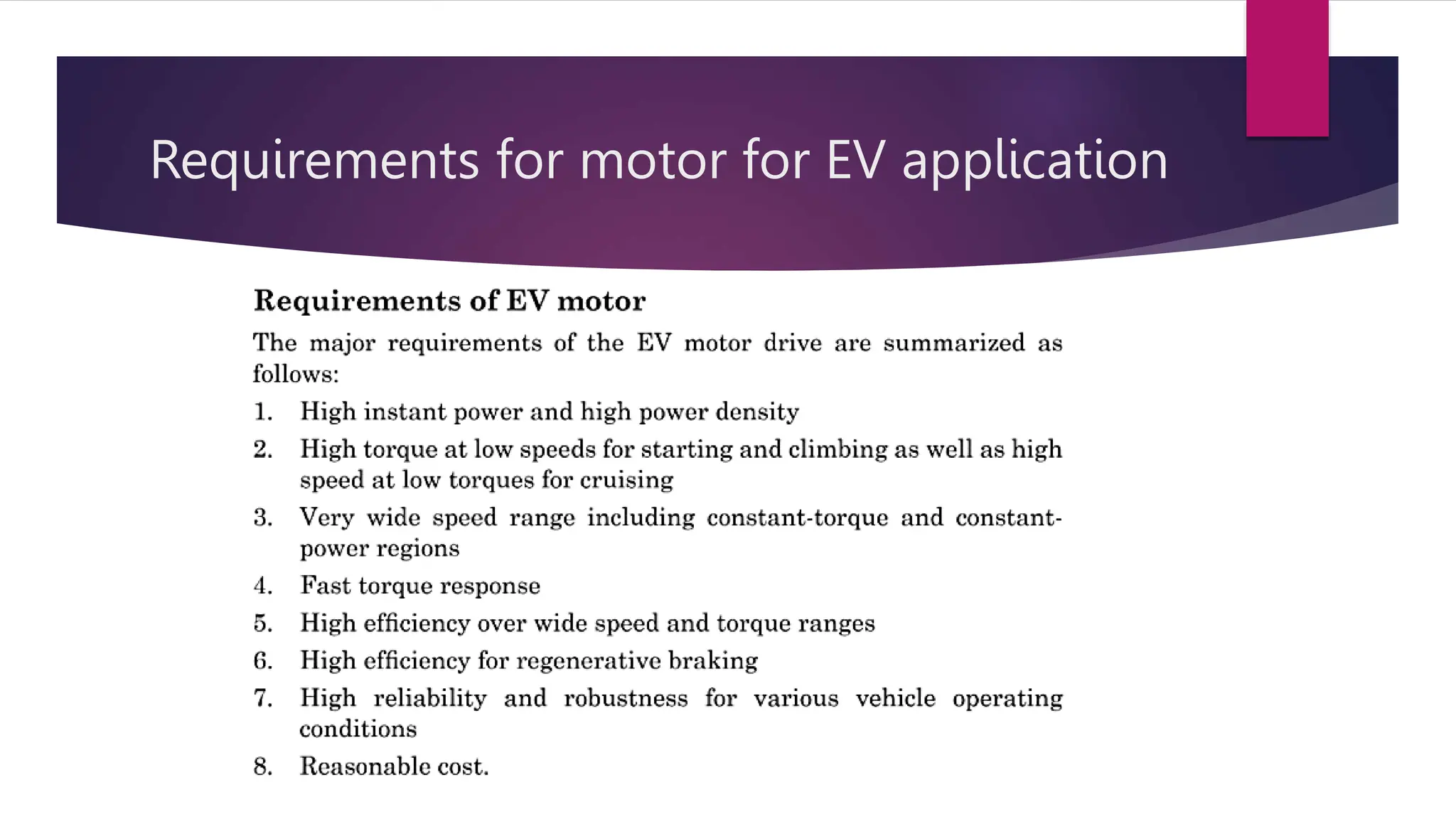
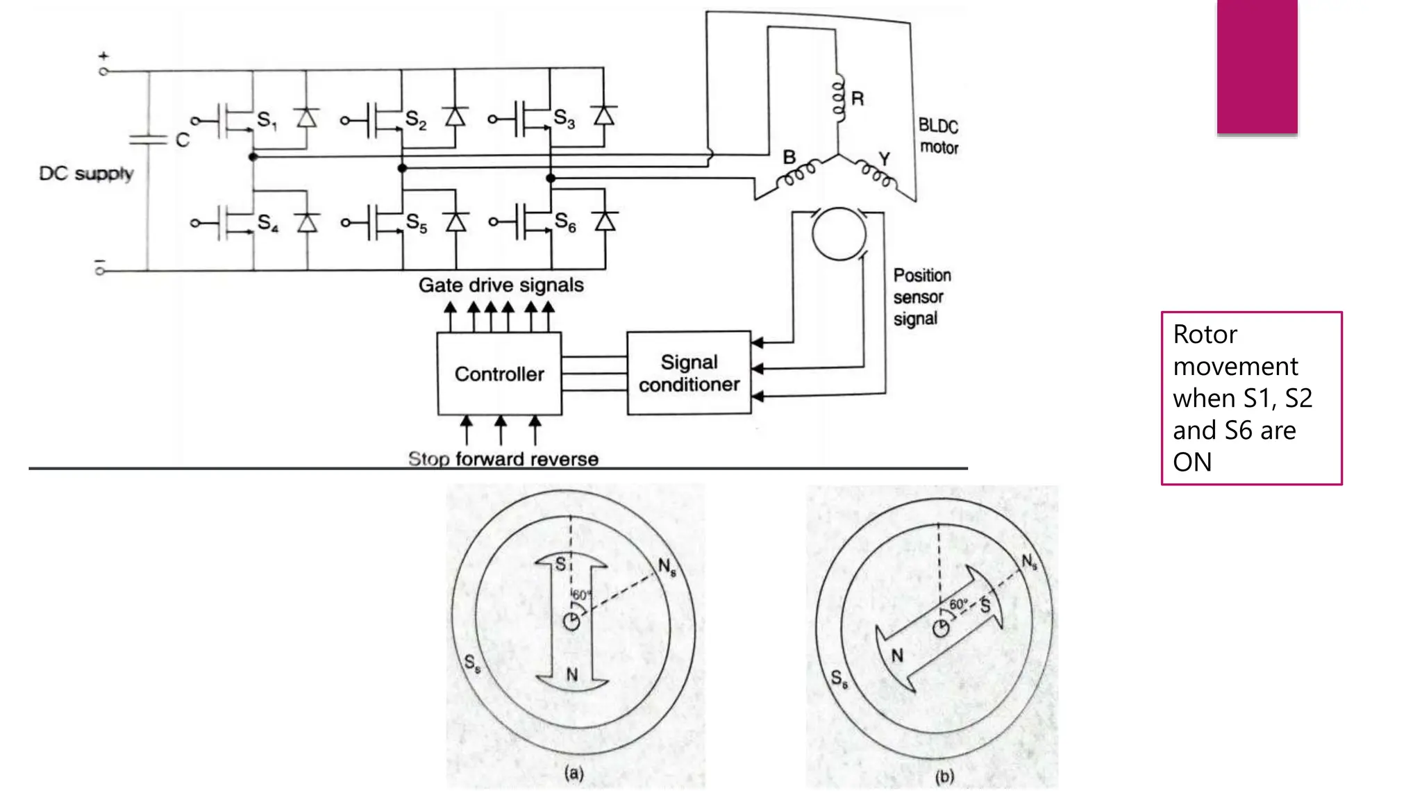
Unit 2 – DC Motors
Contents
 Introduction
 Types ( Series and BLDC )
 Structure, Operation and Control
 Regenerative Braking
 Motor Sizing
Electrification of Road Transport is necessary, through vehicles especially built for
The differentiated needs of this geography.
Waterlogging, Potholes, Heterogeneous Traffic, High temperature
Design for THIS reality NOT THIS
Requirements for motor for EV application
DC Motors
 DC motors are used to turn direct current electrical energy to mechanical energy.
 There are three different types of DC motors; namely, permanent magnet DC motor (PMDC Motor), separately
excited DC motor, and self-excited DC motor.
 Based on the type of electrical connections between the field windings and the armature circuit, self-excited DC
motors are classified into three categories of Series, Shunt, and compound, each with its own unique
characteristics.
DC – Series Motor
 Series DC motors are a group of self-excited DC motors in which the field coil is connected in series to the armature
winding and thus a higher current passes through it.
 A series DC motor mission is to turn the electrical energy into mechanical one based on electromagnetic law. In this
process, the cooperation between the magnetic field present around a current-carrying conductor and an outside field
results in a rotational motion on an output shaft.
In series DC motors, the field windings are connected in series to the armature windings and thus an equal current passes
through them from the supply.
As a result, field coils of such motors are made of thick wires with low resistance and few turns to be able to carry that heavy
load of current.
Application
 DC motors is that they produce high starting torque and operate properly under
heavy load conditions.
 airplanes as engine starters
 start an automobile’s engine
 winches, and hoists
 elevators
Advantages and Challenges
 Producing a high starting torque
 Being cost-effective
 Easy assembly and design
 Easy maintenance.
 Controlling their speed is challenging,
 The increase in the speed comes with a sharp decrease in the torque, and
 As the speed of the motor depends on the load, they cannot be used in many
cases at which the load is removed.
DC Series Motor
Characteristics of a DC series motor
Speed control of DC motor
 The speed control of d.c. series motors can be obtained by two methods
 Flux control method
 Armature-Resistance control method.
Armature-resistance Control
Flux control methods
Field diverters Armature diverter Tapped field control
Flux control methods
Regenerative braking in DC series motor
 Regen braking is possible when the driven load or machinery forces the
motor to run at a speed higher than the no-load speed with a constant
excitation.
 Under this condition, the back emf Eb of the motor is greater than the supply
voltage V, which reverses the direction of motor armature current. The
machine now begins to operate as a generator and the energy generated is
supplied to the source.
Regenerative braking in DC series motor
 Regenerative braking occurs when the motor speed exceeds the no-load speed.
 For series motor, at zero torque, the no-load speed is theoretically infinity.
 Hence one might conclude that the series motor could not operate under
regenerative braking.
 Actually the circuit of the series motor can be altered during the regenerative
braking to allow the machine to generate electric power that can be returned
to the source.
Regenerative braking in DC series motor
Normal series motor
operation
The new configuration for
regenerative braking
Regenerative Braking of DC Series Motors
Applications of Regenerative Braking
 Regenerative braking is used especially where frequent braking and slowing of drives
is required.
 It is most useful in holding a descending load of high potential energy at a constant
speed.
 Regenerative braking is used to control the speed of motors driving loads such as in
electric locomotives, elevators, cranes and hoists.
 Regenerative braking cannot be used for stopping the motor. It is used for controlling
the speed above the no-load speed of the motor driving.
Brushless DC electric motor
 A brushless DC electric motor (BLDC motor or BL motor), also known as
an electronically commutated motor (ECM or EC motor) or synchronous DC motor, is
a synchronous motor using a direct current (DC) electric power supply.
 It uses an electronic closed loop controller to switch DC currents to the
motor windings producing magnetic fields which effectively rotate in space and
which the permanent magnet rotor follows.
 The controller adjusts the phase and amplitude of the dc current pulses to control
the speed and torque of the motor.
 They may also use neodymium magnets and be out runners (the stator is surrounded by the
rotor), in runners (the rotor is surrounded by the stator), or axial (the rotor and stator are flat and
parallel).
 The advantages of a brushless motor over brushed motors are high power-to-weight ratio, high
speed, nearly instantaneous control of speed (rpm) and torque, high efficiency, and low
maintenance. Brushless motors find applications in such places as computer peripherals (disk
drives, printers), hand-held power tools, and vehicles ranging from model aircraft to automobiles.
Construction of a BLDC motor
 Stator
 The structure of the stator of a BLDC Motor
is similar to that of an induction motor.
 It is made up of stacked steel laminations
with axially cut slots for winding.
 The winding in BLDC are slightly different
than that of the traditional induction motor.
 Generally, most BLDC motors consists
of three stator windings that are
connected in star or ‘Y’ fashion
(without a neutral point).
 Additionally, based on the coil
interconnections, the stator windings
are further divided into Trapezoidal
and Sinusoidal Motors.
In a trapezoidal motor, both the drive current and the back EMF are in the shape of a trapezoid
(sinusoidal shape in case of sinusoidal motors). Usually, 48 V (or less) rated motors are used in
automotive and robotics (hybrid cars and robotic arms).
 Rotor
 The rotor part of the BLDC Motor is made up of
permanent magnets (usually, rare earth alloy
magnets like Neodymium (Nd), Samarium Cobalt
(SmCo) and alloy of Neodymium, Ferrite and Boron
(NdFeB)).
 Based on the application, the number of poles can
vary between two and eight with North (N) and
South (S) poles placed alternately
 In the first case, the magnets are placed on the
outer periphery of the rotor.
 The second configuration is called magnetic-
embedded rotor, where rectangular permanent
magnets are embedded into the core of the rotor.
 In the third case, the magnets are inserted into the
iron core of the rotor.
LG direct drive washing machine
Working principle
Rotor
movement
when S1, S2
and S6 are
ON
Rotor
movement
when S2, S4
and S6 are
ON
 For forward (clockwise) rotation , the switches should be operated in the sequence
1,2,6;2,4,6;2,3,4;3,4,5;1,3,5;1,5,6;1,2,6;…….
 For reverse(anti-clockwise) rotation, the switches should be operated in the
sequence 1,2,6;1,5,6;1,3,5;3,4,5;2,3,4;2,4,6;1,2,6;……
 For stopping, keep the switches in the same condition(ON/OFF) corresponding to
the last position.
Commutation action in BLDC motor
Working principle
Inner rotor BLDC motor working animation Outer rotor BLDC motor working animation
Outrunner type BLDC motor
 In this type, the rotor of the motor is present outside and the stator is
present inside.
 It is also called as Hub motors because the wheel is directly
connected to the exterior rotor.
 This type of motors does not require external gear system.
 In a few cases, the motor itself has inbuilt planetary gears.
 This motor makes the overall vehicle less bulky as it does not require
any gear system. It also eliminates the space required for mounting the
motor.
 There is a restriction on the motor dimensions which limits the power
output in the in-runner configuration.
 This motor is widely preferred by electric cycle manufacturers like
Hullikal, Tronx, Spero, light speed bicycles, etc. It is also used by two-
wheeler manufacturers like 22 Motors, NDS Eco Motors, etc.
In-runner type BLDC motor
 In this type, the rotor of the motor is present inside and
the stator is outside like conventional motors.
 These motor require an external transmission system to
transfer the power to the wheels, because of this the out-
runner configuration is little bulky when compared to
the in-runner configuration.
 Many three- wheeler manufacturers like Goenka Electric
Motors, Speego Vehicles, Kinetic Green, Volta
Automotive use BLDC motors.
 Low and medium performance scooter manufacturers
also use BLDC motors for propulsion.
Speed, Torque, Efficiency Curves of a BLDC motor
Control of BLDC motor
Control Scheme for BLDC motor
Microprocessor based control of BLDC
motor
DSP based
control of BLDC
motor
Motor Sizing
• For the electric motor sizing, a demanded power and torque study is necessary.
• The vehicle will be used with many ramps and imperfections, thus requiring
definition of possible critical situations and worse case scenarios, so that the
sizing calculations may be accurate.
• It will be necessary to size a battery pack that is compatible with both the electric
motor and the given route. So, all possible collection courses, their slopes,
conditions and load variations due to collected material, must be considered.
• These data are needed to determine the necessary vehicle travel range that will
be defined in the battery pack design.
Thermal Management of Electric Motors
 Thermal management for electric motors is important as the automotive industry
continues to transition to more electrically dominant vehicle propulsion systems.
 With the push to reduce component size, lower costs, and reduce weight without
sacrificing performance or reliability, the challenges associated with thermal
management for power electronics and electric motors increase.
 The transition to more electrically dominant propulsion systems leads to higher-power
duty cycles for electric drive systems. Thermal constraints place significant limitations
on how electric motors ultimately perform.
 An optimized thermal design can help increase machine rated power substantially,
almost without any increase of its manufacturing costs.
Image Source: NREL
Thermal management impact on motor performan
support increased power
Approach to motor thermal management divided between passive thermal
design and active convective cooling
Passive thermal design refers to the geometrical layout, material selection,
and thermal interfaces that affect the heat-spreading capabilities within
the motor. The ability for heat to spread through the motor affects the
thermal temperature gradients within the motor.
The active convective cooling technology is the cooling mechanism that
ultimately removes the heat from the motor and transfers the heat to
another location to reject the heat to the ambient environment
The material characterization work focuses on the measurement of
mechanical and thermal properties, in collaboration with project partners,
of new individual materials relevant to motor applications
Active cooling The two common approaches highlighted
in Figure for active cooling include: 1) directly cooling the
motor with ATF, and 2) cooling the motor with a cooling
jacket surrounding the stator. The advantages of either
cooling approach depend on the application's coolant
availability, the motor geometry, the motor winding
configuration, and the motor loss distribution. The
advantage of cooling using ATF is that it is possible to
directly cool the motor windings or rotor. P
Heat transfer due to ATF jet impingement will vary over
the end-winding surface.
Passive Thermal Design
The passive thermal stack elements illustrated in
Figures are critical to designing effective thermal
management systems for electric motors. The work
supports improved thermal models for motor
design, but it also enables analysis to compare the
potential impacts of new materials, fabrication
methods, or material processing on motor heat
transfer
The material characterization work focuses on the
measurement of mechanical and thermal properties
of new individual materials relevant to motor
applications. Its work to develop new magnet
materials relevant for electric motor applications.
Focus on comparing the transverse rupture strength
and thermal conductivity of the new magnet
materials with currently available materials
Material Characterization

Unit 2 EHV - I.pptx

  • 1.
    Unit 2 –DC Motors
  • 2.
    Contents  Introduction  Types( Series and BLDC )  Structure, Operation and Control  Regenerative Braking  Motor Sizing
  • 3.
    Electrification of RoadTransport is necessary, through vehicles especially built for The differentiated needs of this geography. Waterlogging, Potholes, Heterogeneous Traffic, High temperature Design for THIS reality NOT THIS
  • 4.
    Requirements for motorfor EV application
  • 6.
    DC Motors  DCmotors are used to turn direct current electrical energy to mechanical energy.  There are three different types of DC motors; namely, permanent magnet DC motor (PMDC Motor), separately excited DC motor, and self-excited DC motor.  Based on the type of electrical connections between the field windings and the armature circuit, self-excited DC motors are classified into three categories of Series, Shunt, and compound, each with its own unique characteristics.
  • 7.
    DC – SeriesMotor  Series DC motors are a group of self-excited DC motors in which the field coil is connected in series to the armature winding and thus a higher current passes through it.  A series DC motor mission is to turn the electrical energy into mechanical one based on electromagnetic law. In this process, the cooperation between the magnetic field present around a current-carrying conductor and an outside field results in a rotational motion on an output shaft.
  • 8.
    In series DCmotors, the field windings are connected in series to the armature windings and thus an equal current passes through them from the supply. As a result, field coils of such motors are made of thick wires with low resistance and few turns to be able to carry that heavy load of current.
  • 9.
    Application  DC motorsis that they produce high starting torque and operate properly under heavy load conditions.  airplanes as engine starters  start an automobile’s engine  winches, and hoists  elevators
  • 10.
    Advantages and Challenges Producing a high starting torque  Being cost-effective  Easy assembly and design  Easy maintenance.  Controlling their speed is challenging,  The increase in the speed comes with a sharp decrease in the torque, and  As the speed of the motor depends on the load, they cannot be used in many cases at which the load is removed.
  • 11.
  • 12.
    Characteristics of aDC series motor
  • 13.
    Speed control ofDC motor  The speed control of d.c. series motors can be obtained by two methods  Flux control method  Armature-Resistance control method.
  • 14.
  • 15.
    Flux control methods Fielddiverters Armature diverter Tapped field control
  • 16.
  • 17.
    Regenerative braking inDC series motor  Regen braking is possible when the driven load or machinery forces the motor to run at a speed higher than the no-load speed with a constant excitation.  Under this condition, the back emf Eb of the motor is greater than the supply voltage V, which reverses the direction of motor armature current. The machine now begins to operate as a generator and the energy generated is supplied to the source.
  • 18.
    Regenerative braking inDC series motor  Regenerative braking occurs when the motor speed exceeds the no-load speed.  For series motor, at zero torque, the no-load speed is theoretically infinity.  Hence one might conclude that the series motor could not operate under regenerative braking.  Actually the circuit of the series motor can be altered during the regenerative braking to allow the machine to generate electric power that can be returned to the source.
  • 19.
    Regenerative braking inDC series motor Normal series motor operation The new configuration for regenerative braking
  • 21.
    Regenerative Braking ofDC Series Motors
  • 22.
    Applications of RegenerativeBraking  Regenerative braking is used especially where frequent braking and slowing of drives is required.  It is most useful in holding a descending load of high potential energy at a constant speed.  Regenerative braking is used to control the speed of motors driving loads such as in electric locomotives, elevators, cranes and hoists.  Regenerative braking cannot be used for stopping the motor. It is used for controlling the speed above the no-load speed of the motor driving.
  • 23.
    Brushless DC electricmotor  A brushless DC electric motor (BLDC motor or BL motor), also known as an electronically commutated motor (ECM or EC motor) or synchronous DC motor, is a synchronous motor using a direct current (DC) electric power supply.  It uses an electronic closed loop controller to switch DC currents to the motor windings producing magnetic fields which effectively rotate in space and which the permanent magnet rotor follows.  The controller adjusts the phase and amplitude of the dc current pulses to control the speed and torque of the motor.
  • 24.
     They mayalso use neodymium magnets and be out runners (the stator is surrounded by the rotor), in runners (the rotor is surrounded by the stator), or axial (the rotor and stator are flat and parallel).  The advantages of a brushless motor over brushed motors are high power-to-weight ratio, high speed, nearly instantaneous control of speed (rpm) and torque, high efficiency, and low maintenance. Brushless motors find applications in such places as computer peripherals (disk drives, printers), hand-held power tools, and vehicles ranging from model aircraft to automobiles.
  • 25.
  • 26.
    Construction of aBLDC motor  Stator  The structure of the stator of a BLDC Motor is similar to that of an induction motor.  It is made up of stacked steel laminations with axially cut slots for winding.  The winding in BLDC are slightly different than that of the traditional induction motor.
  • 27.
     Generally, mostBLDC motors consists of three stator windings that are connected in star or ‘Y’ fashion (without a neutral point).  Additionally, based on the coil interconnections, the stator windings are further divided into Trapezoidal and Sinusoidal Motors. In a trapezoidal motor, both the drive current and the back EMF are in the shape of a trapezoid (sinusoidal shape in case of sinusoidal motors). Usually, 48 V (or less) rated motors are used in automotive and robotics (hybrid cars and robotic arms).
  • 28.
     Rotor  Therotor part of the BLDC Motor is made up of permanent magnets (usually, rare earth alloy magnets like Neodymium (Nd), Samarium Cobalt (SmCo) and alloy of Neodymium, Ferrite and Boron (NdFeB)).  Based on the application, the number of poles can vary between two and eight with North (N) and South (S) poles placed alternately  In the first case, the magnets are placed on the outer periphery of the rotor.  The second configuration is called magnetic- embedded rotor, where rectangular permanent magnets are embedded into the core of the rotor.  In the third case, the magnets are inserted into the iron core of the rotor.
  • 29.
    LG direct drivewashing machine
  • 30.
  • 31.
  • 32.
  • 33.
     For forward(clockwise) rotation , the switches should be operated in the sequence 1,2,6;2,4,6;2,3,4;3,4,5;1,3,5;1,5,6;1,2,6;…….  For reverse(anti-clockwise) rotation, the switches should be operated in the sequence 1,2,6;1,5,6;1,3,5;3,4,5;2,3,4;2,4,6;1,2,6;……  For stopping, keep the switches in the same condition(ON/OFF) corresponding to the last position.
  • 34.
  • 41.
  • 42.
    Inner rotor BLDCmotor working animation Outer rotor BLDC motor working animation
  • 44.
    Outrunner type BLDCmotor  In this type, the rotor of the motor is present outside and the stator is present inside.  It is also called as Hub motors because the wheel is directly connected to the exterior rotor.  This type of motors does not require external gear system.  In a few cases, the motor itself has inbuilt planetary gears.  This motor makes the overall vehicle less bulky as it does not require any gear system. It also eliminates the space required for mounting the motor.  There is a restriction on the motor dimensions which limits the power output in the in-runner configuration.  This motor is widely preferred by electric cycle manufacturers like Hullikal, Tronx, Spero, light speed bicycles, etc. It is also used by two- wheeler manufacturers like 22 Motors, NDS Eco Motors, etc.
  • 45.
    In-runner type BLDCmotor  In this type, the rotor of the motor is present inside and the stator is outside like conventional motors.  These motor require an external transmission system to transfer the power to the wheels, because of this the out- runner configuration is little bulky when compared to the in-runner configuration.  Many three- wheeler manufacturers like Goenka Electric Motors, Speego Vehicles, Kinetic Green, Volta Automotive use BLDC motors.  Low and medium performance scooter manufacturers also use BLDC motors for propulsion.
  • 46.
    Speed, Torque, EfficiencyCurves of a BLDC motor
  • 49.
  • 50.
  • 51.
  • 52.
  • 53.
    Motor Sizing • Forthe electric motor sizing, a demanded power and torque study is necessary. • The vehicle will be used with many ramps and imperfections, thus requiring definition of possible critical situations and worse case scenarios, so that the sizing calculations may be accurate. • It will be necessary to size a battery pack that is compatible with both the electric motor and the given route. So, all possible collection courses, their slopes, conditions and load variations due to collected material, must be considered. • These data are needed to determine the necessary vehicle travel range that will be defined in the battery pack design.
  • 57.
    Thermal Management ofElectric Motors  Thermal management for electric motors is important as the automotive industry continues to transition to more electrically dominant vehicle propulsion systems.  With the push to reduce component size, lower costs, and reduce weight without sacrificing performance or reliability, the challenges associated with thermal management for power electronics and electric motors increase.  The transition to more electrically dominant propulsion systems leads to higher-power duty cycles for electric drive systems. Thermal constraints place significant limitations on how electric motors ultimately perform.  An optimized thermal design can help increase machine rated power substantially, almost without any increase of its manufacturing costs.
  • 58.
    Image Source: NREL Thermalmanagement impact on motor performan support increased power
  • 59.
    Approach to motorthermal management divided between passive thermal design and active convective cooling
  • 60.
    Passive thermal designrefers to the geometrical layout, material selection, and thermal interfaces that affect the heat-spreading capabilities within the motor. The ability for heat to spread through the motor affects the thermal temperature gradients within the motor. The active convective cooling technology is the cooling mechanism that ultimately removes the heat from the motor and transfers the heat to another location to reject the heat to the ambient environment The material characterization work focuses on the measurement of mechanical and thermal properties, in collaboration with project partners, of new individual materials relevant to motor applications
  • 61.
    Active cooling Thetwo common approaches highlighted in Figure for active cooling include: 1) directly cooling the motor with ATF, and 2) cooling the motor with a cooling jacket surrounding the stator. The advantages of either cooling approach depend on the application's coolant availability, the motor geometry, the motor winding configuration, and the motor loss distribution. The advantage of cooling using ATF is that it is possible to directly cool the motor windings or rotor. P
  • 62.
    Heat transfer dueto ATF jet impingement will vary over the end-winding surface.
  • 63.
    Passive Thermal Design Thepassive thermal stack elements illustrated in Figures are critical to designing effective thermal management systems for electric motors. The work supports improved thermal models for motor design, but it also enables analysis to compare the potential impacts of new materials, fabrication methods, or material processing on motor heat transfer
  • 64.
    The material characterizationwork focuses on the measurement of mechanical and thermal properties of new individual materials relevant to motor applications. Its work to develop new magnet materials relevant for electric motor applications. Focus on comparing the transverse rupture strength and thermal conductivity of the new magnet materials with currently available materials Material Characterization