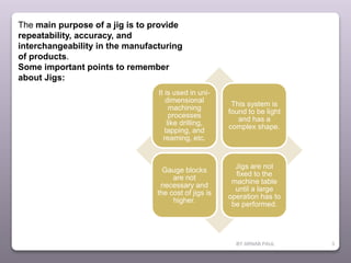
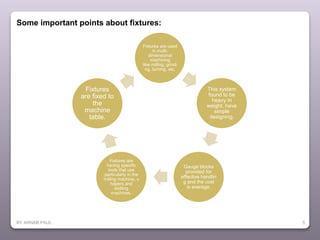
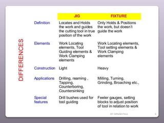
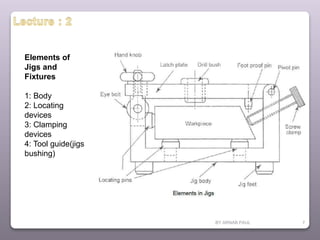
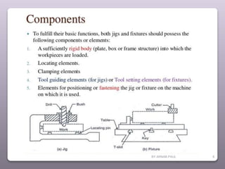
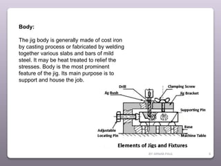
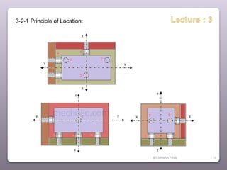
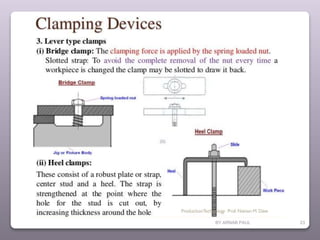
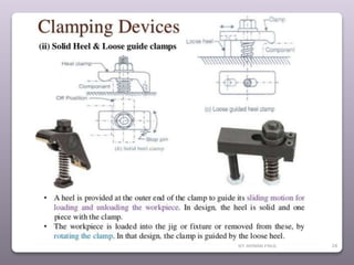
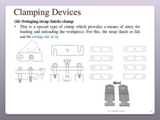
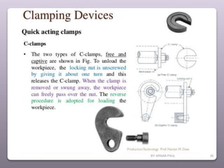
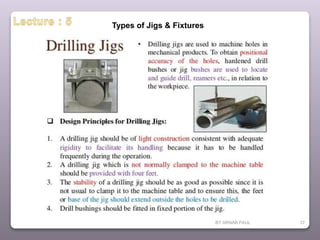
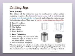
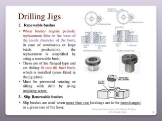
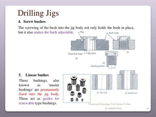
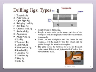
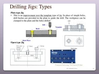
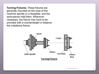
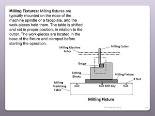
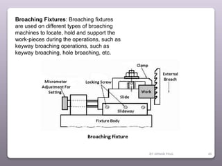
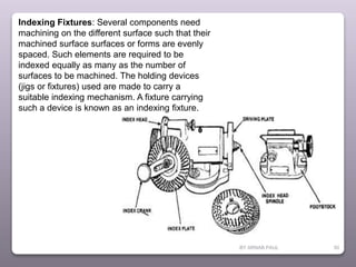
1© ARNAB PAUL
BY ARNAB PAUL 2
Definition of Jig:
A jig is a work-holding device
that holds, supports, and locates the
workpiece and guides the one or
more tools to perform a specific
operation.
In other words, this can also be
defined as, used for holding the tools
and also guiding the cutting tools.
BY ARNAB PAUL 3
The main purpose of a jig is to provide
repeatability, accuracy, and
interchangeability in the manufacturing
of products.
Some important points to remember
about Jigs:
It is used in uni-
dimensional
machining
processes
like drilling,
tapping, and
reaming, etc.
This system is
found to be light
and has a
complex shape.
Gauge blocks
are not
necessary and
the cost of jigs is
higher.
Jigs are not
fixed to the
machine table
until a large
operation has to
be performed.
BY ARNAB PAUL 4
Definition of Fixture:
Fixtures are the work holding device, which holds,
supports and locates the workpiece but not guides
the cutting tool to perform a specific operation.
In other words, the fixtures are only the work
holding device that holds, supports and locates the
workpiece in the desired position to perform any
operation.
The main purpose of the fixtures is to hold and
locate the workpiece during any machining
operation and to provide repeatability, accuracy,
and interchangeability in the manufacturing of
products.
BY ARNAB PAUL 5
Some important points about fixtures:
Fixtures are used
in multi-
dimensional
machining
like milling, grindi
ng, turning, etc.
This system
found to be
heavy in
weight, have
simple
designing.
Gauge blocks
provided for
effective handlin
g and the cost
is average.
Fixtures are
having specific
tools that use
particularly in the
milling machine, s
hapers and
slotting
machines.
Fixtures
are fixed to
the
machine
table.
BY ARNAB PAUL 6
BY ARNAB PAUL 7
Elements of
Jigs and
Fixtures
1: Body
2: Locating
devices
3: Clamping
devices
4: Tool guide(jigs
bushing)
BY ARNAB PAUL 8
BY ARNAB PAUL 9
Body:
The jig body is generally made of cost iron
by casting process or fabricated by welding
together various slabs and bars of mild
steel. It may be heat treated to relief the
stresses. Body is the most prominent
feature of the jig. Its main purpose is to
support and house the job.
BY ARNAB PAUL 10
3-2-1 Principle of Location:
BY ARNAB PAUL 11
Degrees of Freedom in space
A work-piece free in space can move in an infinite
number of direction. For analysis, this motion can
be broken down into 12 directional movements or
"degrees of freedom". All 12 degrees of freedom
must be restricted to ensure proper referencing of a
work-piece.
As shown in Fig 1, the 12 degrees of freedom all
relate to the central axis of the work-piece. Notice
the 6 axial degrees and 6 radial degrees of
freedom. The axial degrees of freedom permit
straight-line movement in both directions along
the 3 principle axis shown as X, Y & Z.
The radial degrees of freedom permit rotational
movement, in both clockwise & counterclockwise
radial directions around the same three axis.
BY ARNAB PAUL 12
BY ARNAB PAUL 13
Primary Locators
First the three locators or supports are placed under the
work-piece. It will be positioned on the primary locating
surface also known as datum. It will restrict 5 degrees of
freedom.
•Axial Movement downward along Z- axis ( No.6 in Fig 2 )
•Rotation about the X & Y axis ( No. 7, 8, 9 & 10 in Fig 2 )
BY ARNAB PAUL 14
Secondary Locators
The next two locators are normally placed on the secondary
surface, restricting an additional 3 degrees of freedom.
Axial movement along the Y+ axis ( No.3 in Fig 2 )
Rotation about the Z axis ( No. 11 & 12 in Fig 2 )
BY ARNAB PAUL 15
Tertiary Locator
This locator is positioned at the end of the part. It restricts 1 degrees
of freedom
Axial movement along the X axis ( No.2 in Fig 2 )
BY ARNAB PAUL 16
BY ARNAB PAUL 17
BY ARNAB PAUL 18
19
BY ARNAB PAUL
BY ARNAB PAUL 20
BY ARNAB PAUL 21
BY ARNAB PAUL 22
BY ARNAB PAUL 23
BY ARNAB PAUL 24
BY ARNAB PAUL 25
BY ARNAB PAUL 26
BY ARNAB PAUL 27
BY ARNAB PAUL 28
BY ARNAB PAUL 29
BY ARNAB PAUL 30
BY ARNAB PAUL 31
Using gooseneck clamps is one way to reduce the height of the clamps.
BY ARNAB PAUL 32
BY ARNAB PAUL 33
Fool-Proofing:
BY ARNAB PAUL 34
BY ARNAB PAUL 35
6: Inserts:
To avoid any damage to fragile and soft work piece and also to the
finished surfaces of the work piece while clamping. Inserts of some soft
material such as copper, lead , fiber , leather , hard rubber and plastic
should be fitted to the faces of the clamps.
7: Design for Safety:
Jigs and fixtures must be safe and convenient in use, following are the
some
Factors for the safety of worker working on jigs and fixtures.
(A): Sharp corner on the body of jig and fixture should be avoided.
(B): Sighting surfaces should be cleared.
(C): Bolt and nut should be inside the body of jig or fixture and not
protrude on the surface.
BY ARNAB PAUL 36
8: Sighting Surface:
Machining on the work piece must be clearly visible to the worker. He
should not be required to bend is neck for seeing the work piece or
work surfaces.
9: Simplicity in design:
Design of the jig and fixture should be a simple one. A completed
design require a large maintenance. They should be easily to set ,
cheap in manufacture.
10: Economical:
Jig and fixtures should be simple in construction, give high accuracy ,
be sufficiently rigid and lightly weight. To satisfy these conditions an
economical balance has to be made.
BY ARNAB PAUL 37
Types of Jigs & Fixtures
BY ARNAB PAUL 38
BY ARNAB PAUL 39
BY ARNAB PAUL 40
BY ARNAB PAUL 41
BY ARNAB PAUL 42
BY ARNAB PAUL 43
BY ARNAB PAUL 44
BY ARNAB PAUL 45
BY ARNAB PAUL 46
BY ARNAB PAUL 47
Turning Fixtures: These fixtures are
generally mounted on the nose of the
machine spindle or a faceplate, and the
work-pieces held them. Whenever
necessary, the fixture may have to be
provided with a counterweight or balance
the unbalance fixture.
BY ARNAB PAUL 48
Milling Fixtures: Milling fixtures are
typically mounted on the nose of the
machine spindle or a faceplate, and the
work-pieces held them. The table is shifted
and set in proper position, in relation to the
cutter. The work-pieces are located in the
base of the fixture and clamped before
starting the operation.
BY ARNAB PAUL 49
Broaching Fixtures: Broaching fixtures
are used on different types of broaching
machines to locate, hold and support the
work-pieces during the operations, such as
keyway broaching operations, such as
keyway broaching, hole broaching, etc.
BY ARNAB PAUL 50
Indexing Fixtures: Several components need
machining on the different surface such that their
machined surface surfaces or forms are evenly
spaced. Such elements are required to be
indexed equally as many as the number of
surfaces to be machined. The holding devices
(jigs or fixtures) used are made to carry a
suitable indexing mechanism. A fixture carrying
such a device is known as an indexing fixture.
BY ARNAB PAUL 51
Grinding Fixtures: These fixtures may be the standard work-holding
devices, such as chucks, mandrels, chuck with shaped jaws, magnetic
chucks, etc.
Boring Fixtures: This fixture incorporates almost all the prevailing principles
of jig and fixture design, their construction need not be as sturdy as that of
the milling fixtures, because they never have to bear as heavy cutting loads
as involved in milling fixtures, because they never have to endure as heavy
cutting loads as involved in milling operations.
Tapping Fixtures: Tapping fixture is specially designed to position and firmly
secure identical work-pieces for cutting internal threads in drilled holes in
them. Odd shaped and unbalanced components will always need the use of
such fixtures, especially when the tapping operation is to be carried out
repeatedly on a mass scale on such parts.
BY ARNAB PAUL 52
Welding Fixtures:
Welding fixtures are carefully designed to hold and support the various
components to be welded in proper locations and prevent distortions in
welded structures. For this, the locating element need to be carefully;
clamping has to be light but firm, placement of clamping elements has to
be clear of the welding area. The fixture has to be quite stable and rigid
to withstand the welding stresses.
Assembly Fixtures:
The function of these fixtures is to hold different components together in
their proper relative position at the time of assembling them.

Jigs & Fixtures

  • 1.
  • 2.
    BY ARNAB PAUL2 Definition of Jig: A jig is a work-holding device that holds, supports, and locates the workpiece and guides the one or more tools to perform a specific operation. In other words, this can also be defined as, used for holding the tools and also guiding the cutting tools.
  • 3.
    BY ARNAB PAUL3 The main purpose of a jig is to provide repeatability, accuracy, and interchangeability in the manufacturing of products. Some important points to remember about Jigs: It is used in uni- dimensional machining processes like drilling, tapping, and reaming, etc. This system is found to be light and has a complex shape. Gauge blocks are not necessary and the cost of jigs is higher. Jigs are not fixed to the machine table until a large operation has to be performed.
  • 4.
    BY ARNAB PAUL4 Definition of Fixture: Fixtures are the work holding device, which holds, supports and locates the workpiece but not guides the cutting tool to perform a specific operation. In other words, the fixtures are only the work holding device that holds, supports and locates the workpiece in the desired position to perform any operation. The main purpose of the fixtures is to hold and locate the workpiece during any machining operation and to provide repeatability, accuracy, and interchangeability in the manufacturing of products.
  • 5.
    BY ARNAB PAUL5 Some important points about fixtures: Fixtures are used in multi- dimensional machining like milling, grindi ng, turning, etc. This system found to be heavy in weight, have simple designing. Gauge blocks provided for effective handlin g and the cost is average. Fixtures are having specific tools that use particularly in the milling machine, s hapers and slotting machines. Fixtures are fixed to the machine table.
  • 6.
  • 7.
    BY ARNAB PAUL7 Elements of Jigs and Fixtures 1: Body 2: Locating devices 3: Clamping devices 4: Tool guide(jigs bushing)
  • 8.
  • 9.
    BY ARNAB PAUL9 Body: The jig body is generally made of cost iron by casting process or fabricated by welding together various slabs and bars of mild steel. It may be heat treated to relief the stresses. Body is the most prominent feature of the jig. Its main purpose is to support and house the job.
  • 10.
    BY ARNAB PAUL10 3-2-1 Principle of Location:
  • 11.
    BY ARNAB PAUL11 Degrees of Freedom in space A work-piece free in space can move in an infinite number of direction. For analysis, this motion can be broken down into 12 directional movements or "degrees of freedom". All 12 degrees of freedom must be restricted to ensure proper referencing of a work-piece. As shown in Fig 1, the 12 degrees of freedom all relate to the central axis of the work-piece. Notice the 6 axial degrees and 6 radial degrees of freedom. The axial degrees of freedom permit straight-line movement in both directions along the 3 principle axis shown as X, Y & Z. The radial degrees of freedom permit rotational movement, in both clockwise & counterclockwise radial directions around the same three axis.
  • 12.
  • 13.
    BY ARNAB PAUL13 Primary Locators First the three locators or supports are placed under the work-piece. It will be positioned on the primary locating surface also known as datum. It will restrict 5 degrees of freedom. •Axial Movement downward along Z- axis ( No.6 in Fig 2 ) •Rotation about the X & Y axis ( No. 7, 8, 9 & 10 in Fig 2 )
  • 14.
    BY ARNAB PAUL14 Secondary Locators The next two locators are normally placed on the secondary surface, restricting an additional 3 degrees of freedom. Axial movement along the Y+ axis ( No.3 in Fig 2 ) Rotation about the Z axis ( No. 11 & 12 in Fig 2 )
  • 15.
    BY ARNAB PAUL15 Tertiary Locator This locator is positioned at the end of the part. It restricts 1 degrees of freedom Axial movement along the X axis ( No.2 in Fig 2 )
  • 16.
  • 17.
  • 18.
  • 19.
  • 20.
  • 21.
  • 22.
  • 23.
  • 24.
  • 25.
  • 26.
  • 27.
  • 28.
  • 29.
  • 30.
  • 31.
    BY ARNAB PAUL31 Using gooseneck clamps is one way to reduce the height of the clamps.
  • 32.
  • 33.
    BY ARNAB PAUL33 Fool-Proofing:
  • 34.
  • 35.
    BY ARNAB PAUL35 6: Inserts: To avoid any damage to fragile and soft work piece and also to the finished surfaces of the work piece while clamping. Inserts of some soft material such as copper, lead , fiber , leather , hard rubber and plastic should be fitted to the faces of the clamps. 7: Design for Safety: Jigs and fixtures must be safe and convenient in use, following are the some Factors for the safety of worker working on jigs and fixtures. (A): Sharp corner on the body of jig and fixture should be avoided. (B): Sighting surfaces should be cleared. (C): Bolt and nut should be inside the body of jig or fixture and not protrude on the surface.
  • 36.
    BY ARNAB PAUL36 8: Sighting Surface: Machining on the work piece must be clearly visible to the worker. He should not be required to bend is neck for seeing the work piece or work surfaces. 9: Simplicity in design: Design of the jig and fixture should be a simple one. A completed design require a large maintenance. They should be easily to set , cheap in manufacture. 10: Economical: Jig and fixtures should be simple in construction, give high accuracy , be sufficiently rigid and lightly weight. To satisfy these conditions an economical balance has to be made.
  • 37.
    BY ARNAB PAUL37 Types of Jigs & Fixtures
  • 38.
  • 39.
  • 40.
  • 41.
  • 42.
  • 43.
  • 44.
  • 45.
  • 46.
  • 47.
    BY ARNAB PAUL47 Turning Fixtures: These fixtures are generally mounted on the nose of the machine spindle or a faceplate, and the work-pieces held them. Whenever necessary, the fixture may have to be provided with a counterweight or balance the unbalance fixture.
  • 48.
    BY ARNAB PAUL48 Milling Fixtures: Milling fixtures are typically mounted on the nose of the machine spindle or a faceplate, and the work-pieces held them. The table is shifted and set in proper position, in relation to the cutter. The work-pieces are located in the base of the fixture and clamped before starting the operation.
  • 49.
    BY ARNAB PAUL49 Broaching Fixtures: Broaching fixtures are used on different types of broaching machines to locate, hold and support the work-pieces during the operations, such as keyway broaching operations, such as keyway broaching, hole broaching, etc.
  • 50.
    BY ARNAB PAUL50 Indexing Fixtures: Several components need machining on the different surface such that their machined surface surfaces or forms are evenly spaced. Such elements are required to be indexed equally as many as the number of surfaces to be machined. The holding devices (jigs or fixtures) used are made to carry a suitable indexing mechanism. A fixture carrying such a device is known as an indexing fixture.
  • 51.
    BY ARNAB PAUL51 Grinding Fixtures: These fixtures may be the standard work-holding devices, such as chucks, mandrels, chuck with shaped jaws, magnetic chucks, etc. Boring Fixtures: This fixture incorporates almost all the prevailing principles of jig and fixture design, their construction need not be as sturdy as that of the milling fixtures, because they never have to bear as heavy cutting loads as involved in milling fixtures, because they never have to endure as heavy cutting loads as involved in milling operations. Tapping Fixtures: Tapping fixture is specially designed to position and firmly secure identical work-pieces for cutting internal threads in drilled holes in them. Odd shaped and unbalanced components will always need the use of such fixtures, especially when the tapping operation is to be carried out repeatedly on a mass scale on such parts.
  • 52.
    BY ARNAB PAUL52 Welding Fixtures: Welding fixtures are carefully designed to hold and support the various components to be welded in proper locations and prevent distortions in welded structures. For this, the locating element need to be carefully; clamping has to be light but firm, placement of clamping elements has to be clear of the welding area. The fixture has to be quite stable and rigid to withstand the welding stresses. Assembly Fixtures: The function of these fixtures is to hold different components together in their proper relative position at the time of assembling them.