Module 3_Theory of bending operation in sheet metal
1.
Module No. 3
Theoryof Bending
Lokpriya Gaikwad
Mechanical - 2023 - 24 - PTD
Dr. Lokpriya Gaikwad
Assistant Professor
Dept. of Mechanical Engineering ,
SIES Graduate School of Technology
1
2.
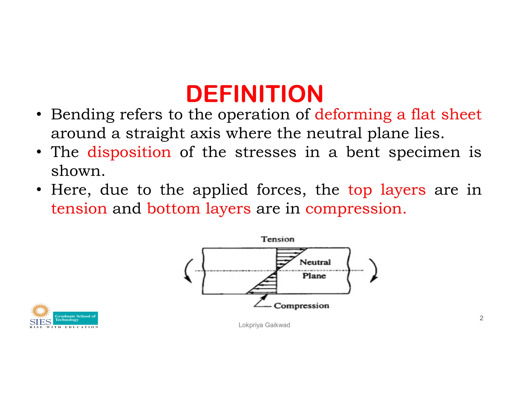
DEFINITION
• Bending refersto the operation of deforming a flat sheet
around a straight axis where the neutral plane lies.
• The disposition of the stresses in a bent specimen is
shown.
• Here, due to the applied forces, the top layers are in
tension and bottom layers are in compression.
Lokpriya Gaikwad
2
tension and bottom layers are in compression.
3.
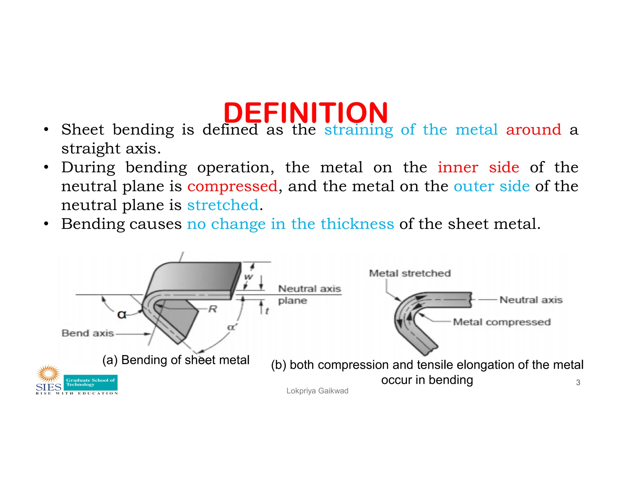
DEFINITION
• Sheet bendingis defined as the straining of the metal around a
straight axis.
• During bending operation, the metal on the inner side of the
neutral plane is compressed, and the metal on the outer side of the
neutral plane is stretched.
• Bending causes no change in the thickness of the sheet metal.
Lokpriya Gaikwad
3
(a) Bending of sheet metal (b) both compression and tensile elongation of the metal
occur in bending
4.
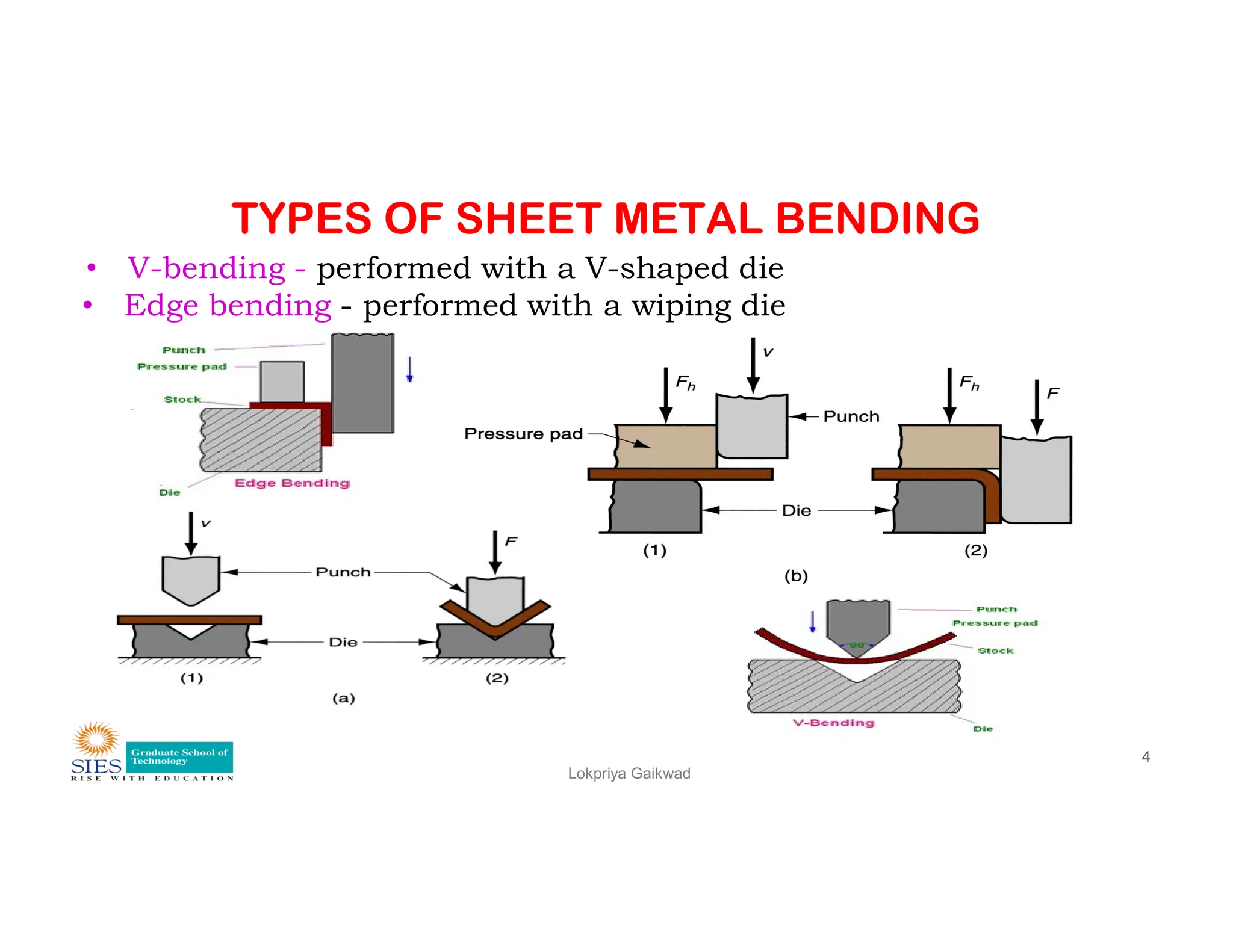
TYPES OF SHEETMETAL BENDING
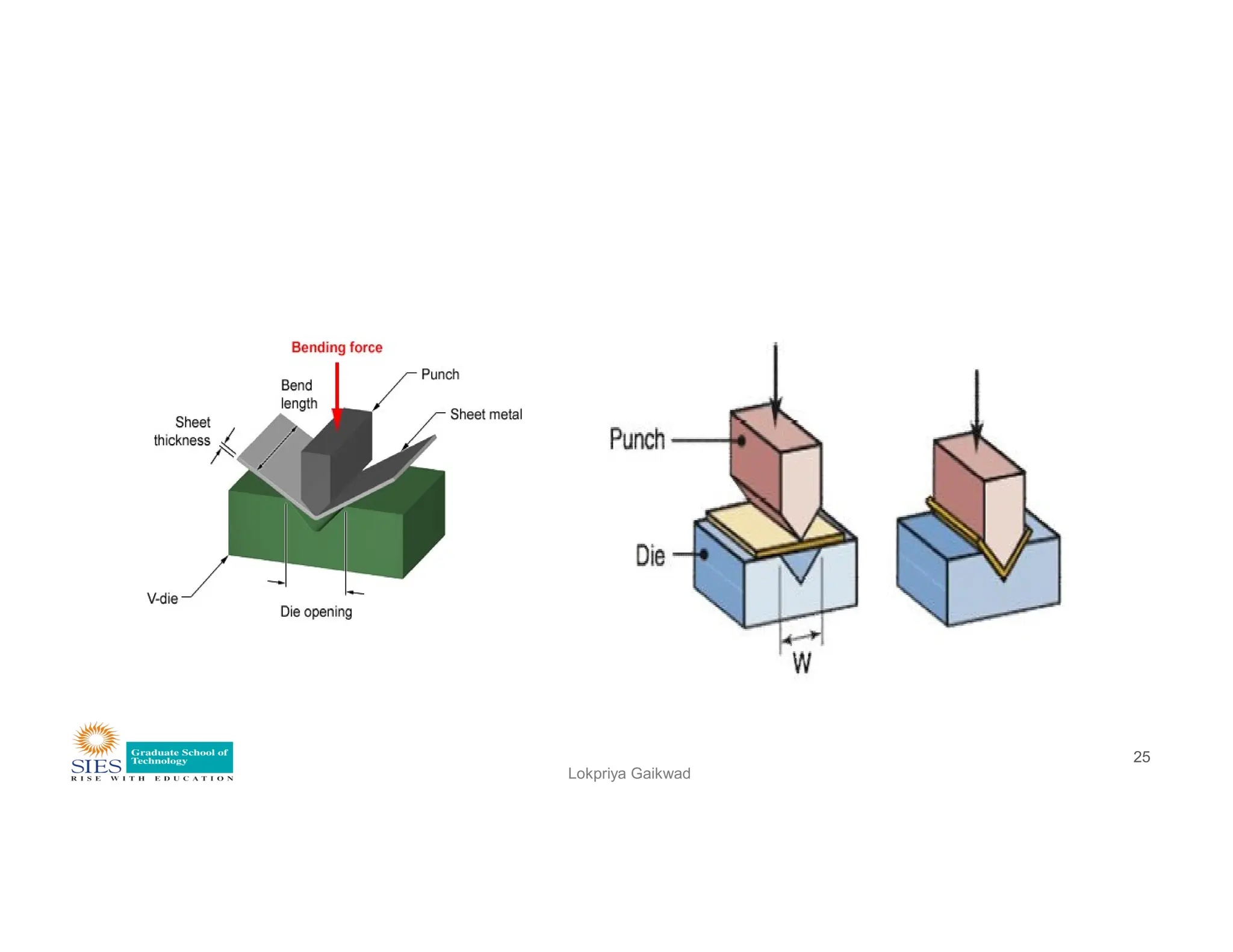
• V-bending - performed with a V-shaped die
• Edge bending - performed with a wiping die
Lokpriya Gaikwad
4
5.
TYPES OF SHEETMETAL BENDING
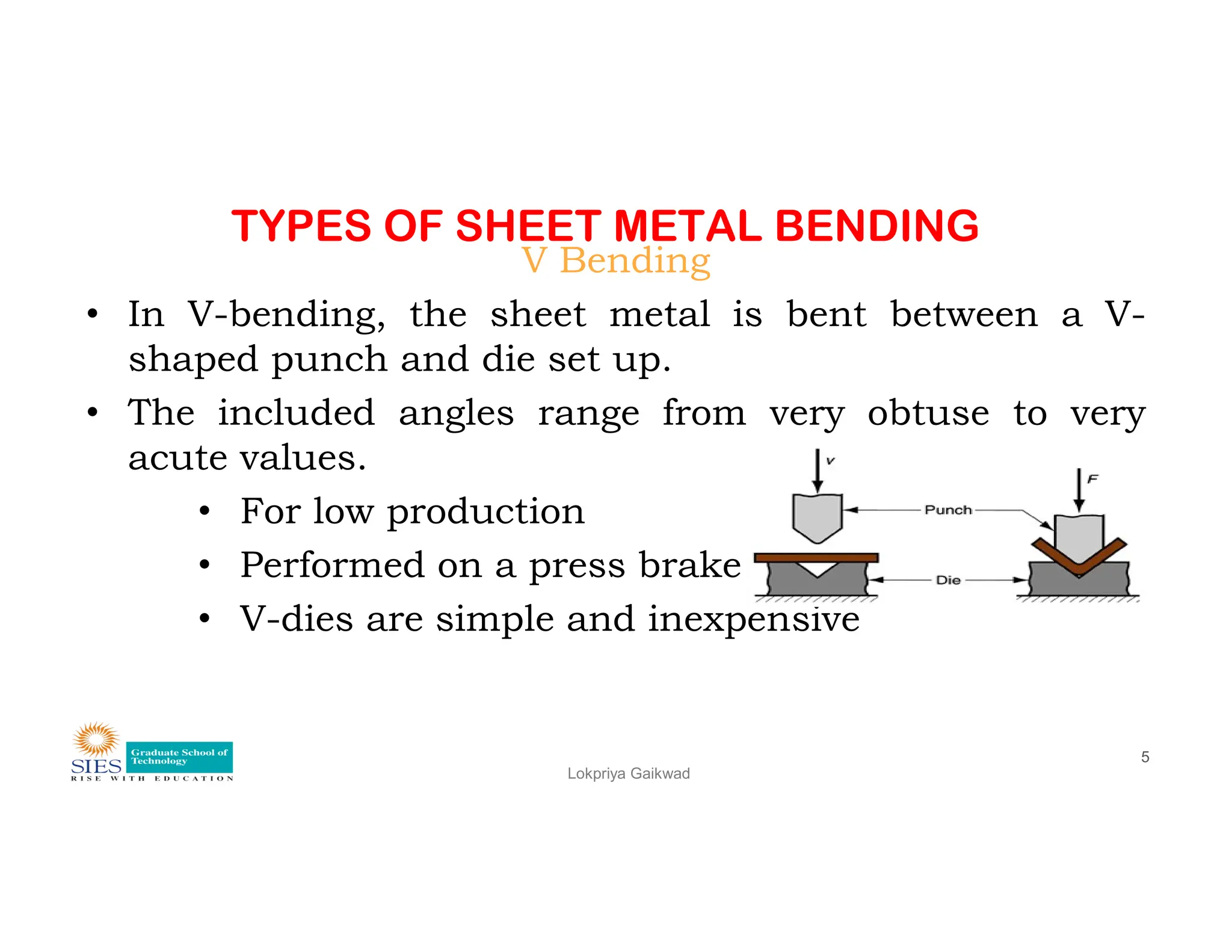
V Bending
• In V-bending, the sheet metal is bent between a V-
shaped punch and die set up.
• The included angles range from very obtuse to very
acute values.
Lokpriya Gaikwad
5
acute values.
• For low production
• Performed on a press brake
• V-dies are simple and inexpensive
6.
TYPES OF SHEETMETAL BENDING
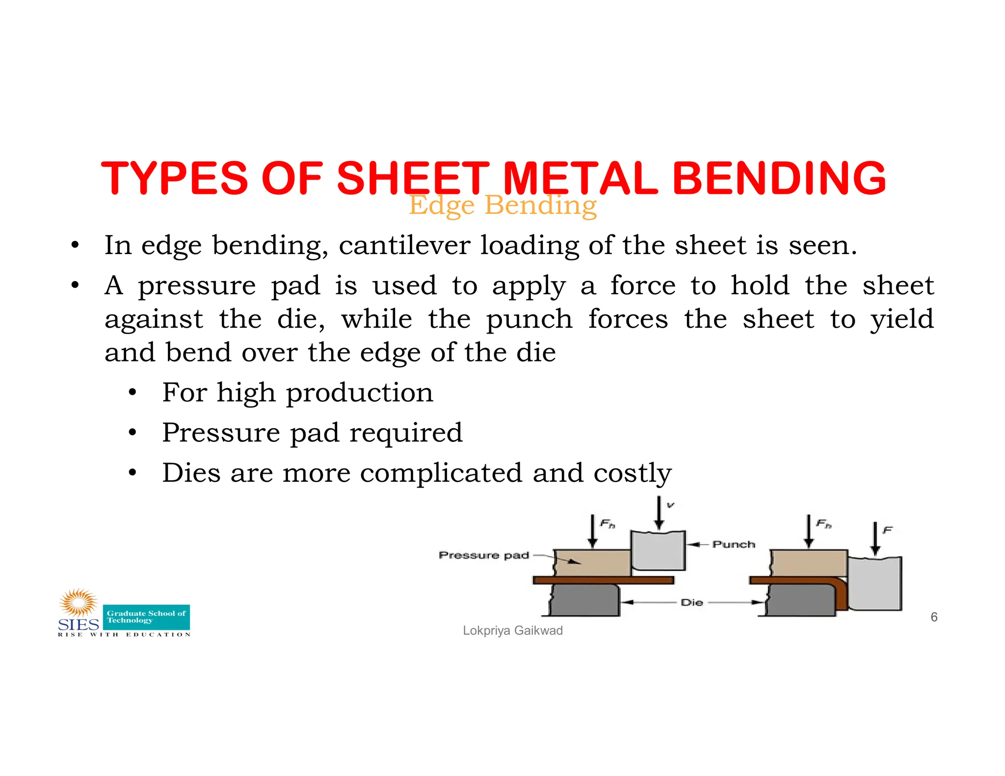
Edge Bending
• In edge bending, cantilever loading of the sheet is seen.
• A pressure pad is used to apply a force to hold the sheet
against the die, while the punch forces the sheet to yield
and bend over the edge of the die
• For high production
Lokpriya Gaikwad
6
• For high production
• Pressure pad required
• Dies are more complicated and costly
BEND RADIUS
• Itis the radius of curvature on the inside or concave surface of the
bend.
• To prevent the cracking of the material on the outer tensile
surface, the bend radius cannot be made smaller than a certain
value.
Lokpriya Gaikwad
9
value.
• Very ductile material can have zero bend radius.
• i.e. they can be folded upon themselves.
• To prevent damage to the punch and die, bent radius should not
be less than 0.8 mm
• Soft material can be bent 180˚ with a radius = or less than the
stock thickness.
10.
BEND RADIUS
• Whenbending to an angle of 90, the minimum bend
radius
• = 2 to 5 t for C-steel
= 1 t for SS
Lokpriya Gaikwad
10
• = 1 t for SS
• = 2 to 3.5 t for Titanium alloy
• = 0.3 to 0.5 t for brass
• = 0.35 t for AL
11.
DEVELOPED LENGTH (BENDALLOWANCE)
• A component is usually blanked (or sheared) before bending.
• Consequently it is necessary to calculate the length before bending
or the developed length of the workpiece before the blanking tool
can be designed.
• During bending the metal layers adjacent to the inner surface are
compressed whereas the metal layers near the external surface are
Lokpriya Gaikwad
11
compressed whereas the metal layers near the external surface are
stretched.
• The plane (layer) which is neither compressed nor stretched is
called the neutral plane.
• The neutral plane lies along the middle of the sheet thickness for
radii exceeding twice the thickness.
12.
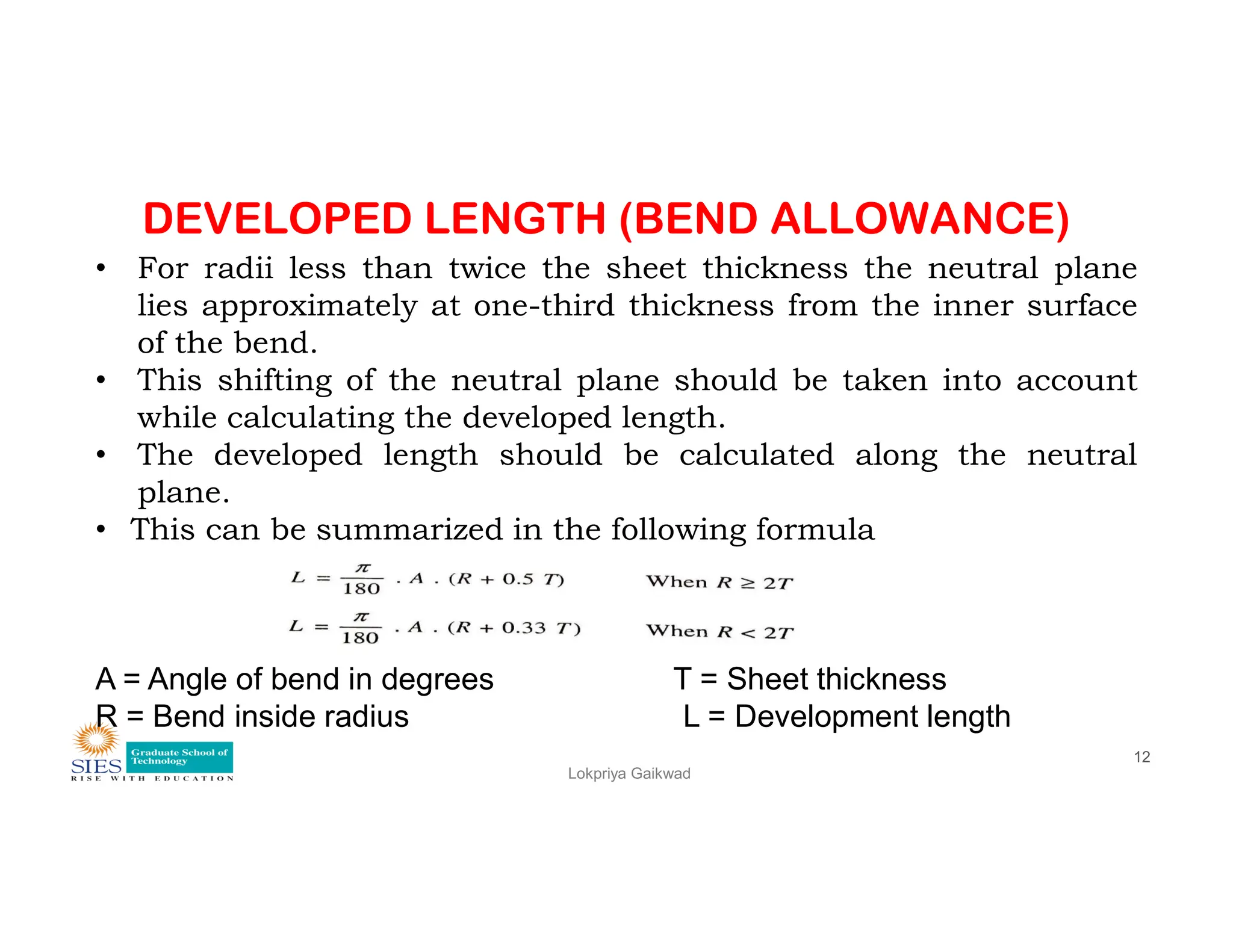
DEVELOPED LENGTH (BENDALLOWANCE)
• For radii less than twice the sheet thickness the neutral plane
lies approximately at one-third thickness from the inner surface
of the bend.
• This shifting of the neutral plane should be taken into account
while calculating the developed length.
• The developed length should be calculated along the neutral
plane.
Lokpriya Gaikwad
12
plane.
• This can be summarized in the following formula
A = Angle of bend in degrees T = Sheet thickness
R = Bend inside radius L = Development length
13.
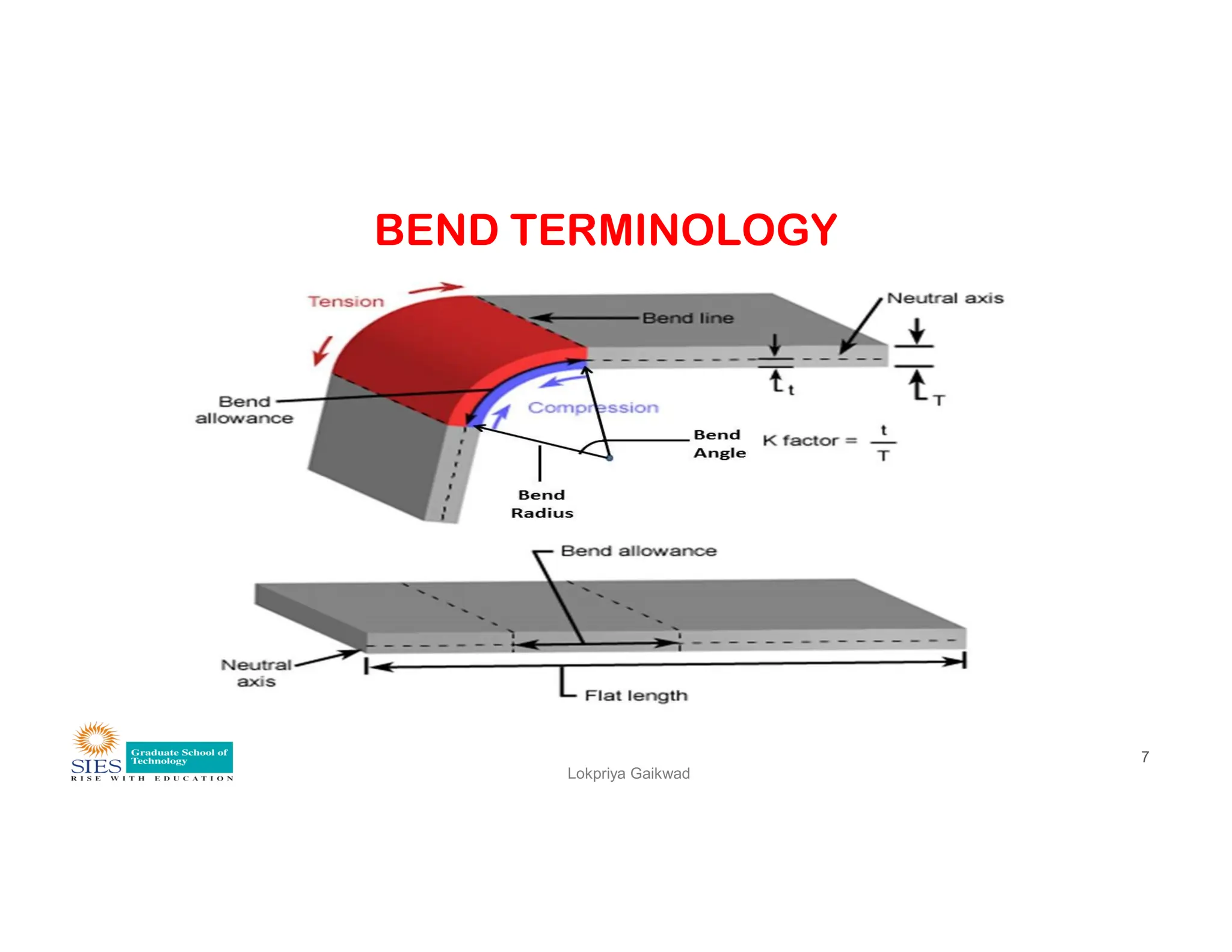
BEND ALLOWANCE (DEVELOPEDLENGTH)
• The Bend Allowance is the arc length of the bend as
measured along the neutral axis of the material.
• The Bend Allowance is defined as the material that
have to be added to the initial length of flat sheet in
order to arrive at the length of formed part.
Lokpriya Gaikwad
13
order to arrive at the length of formed part.
• BA is added to the length of the straight legs of the part
to get blank length.
• As it was mentioned before the length of the neutral
axis doesn’t change after the bending.
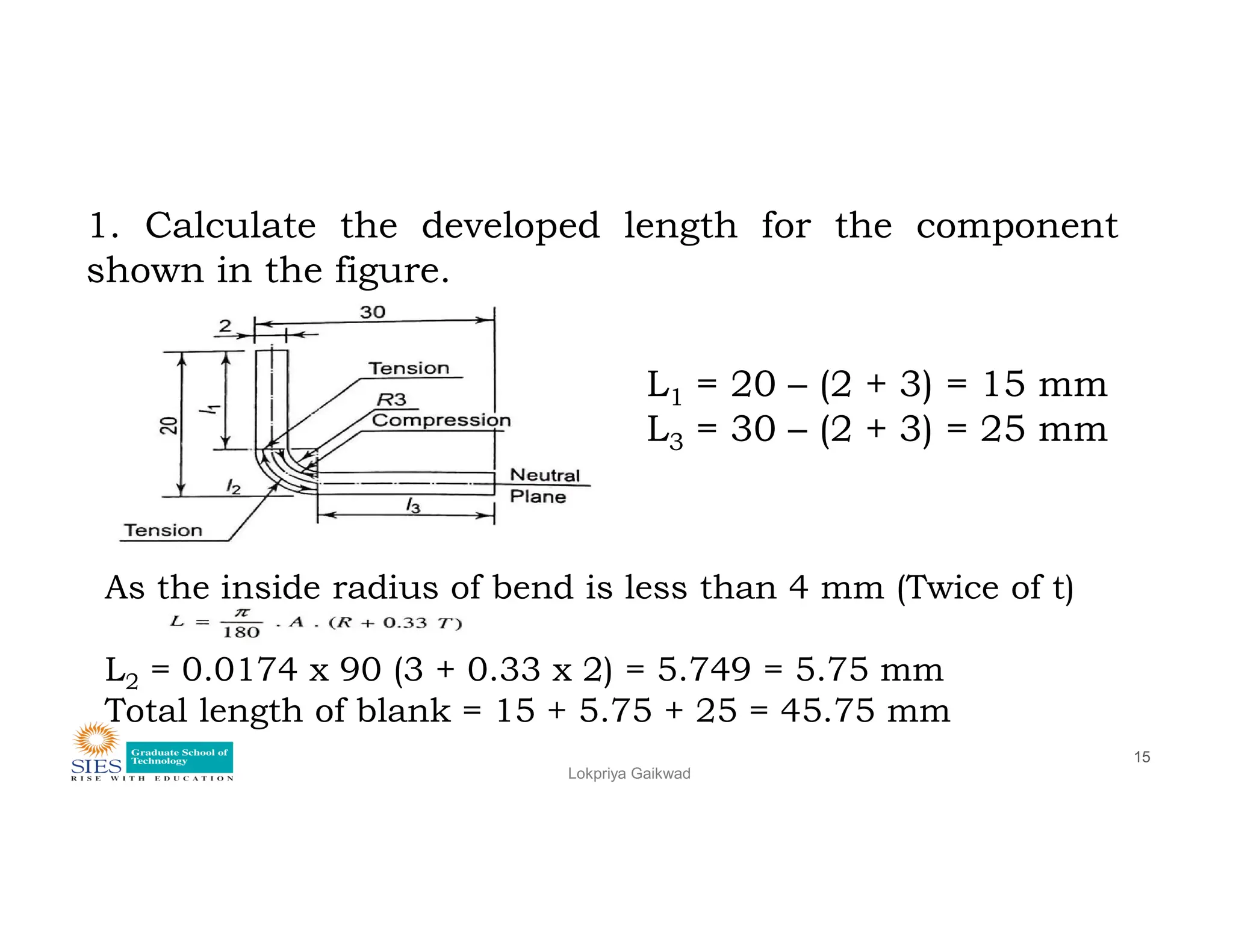
1. Calculate thedeveloped length for the component
shown in the figure.
L1 = 20 – (2 + 3) = 15 mm
L3 = 30 – (2 + 3) = 25 mm
Lokpriya Gaikwad
15
As the inside radius of bend is less than 4 mm (Twice of t)
L2 = 0.0174 x 90 (3 + 0.33 x 2) = 5.749 = 5.75 mm
Total length of blank = 15 + 5.75 + 25 = 45.75 mm
16.
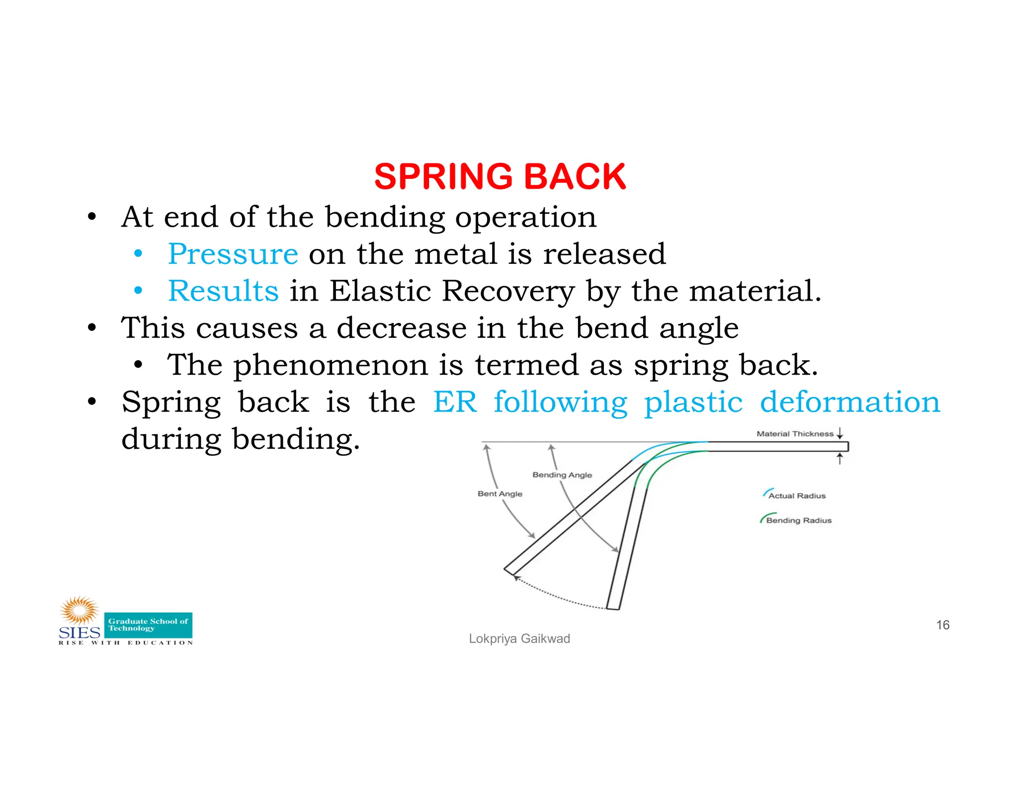
SPRING BACK
• Atend of the bending operation
• Pressure on the metal is released
• Results in Elastic Recovery by the material.
• This causes a decrease in the bend angle
• The phenomenon is termed as spring back.
• Spring back is the ER following plastic deformation
Lokpriya Gaikwad
16
• Spring back is the ER following plastic deformation
during bending.
17.
SPRING BACK
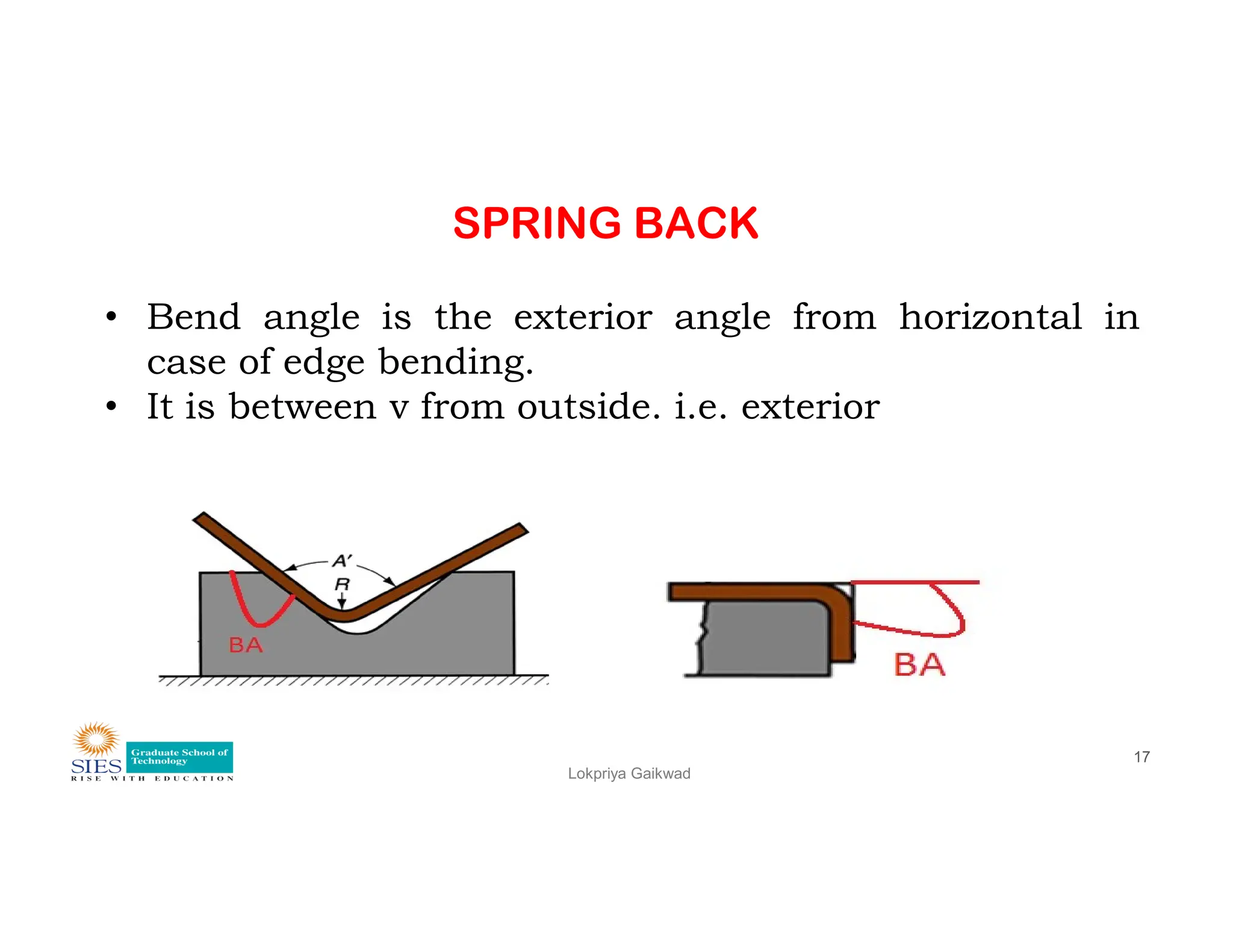
• Bendangle is the exterior angle from horizontal in
case of edge bending.
• It is between v from outside. i.e. exterior
Lokpriya Gaikwad
17
18.
SPRING BACK
• SBresults in
• increase in included angle of bent part
• relative to included angle of tool after tool is
removed.
• Reason for spring back:
Lokpriya Gaikwad
18
• Reason for spring back:
• When bending pressure is removed
• elastic energy remains in bent part,
• causing it to recover partially toward its original
shape
19.
SPRING BACK
Lokpriya Gaikwad
19
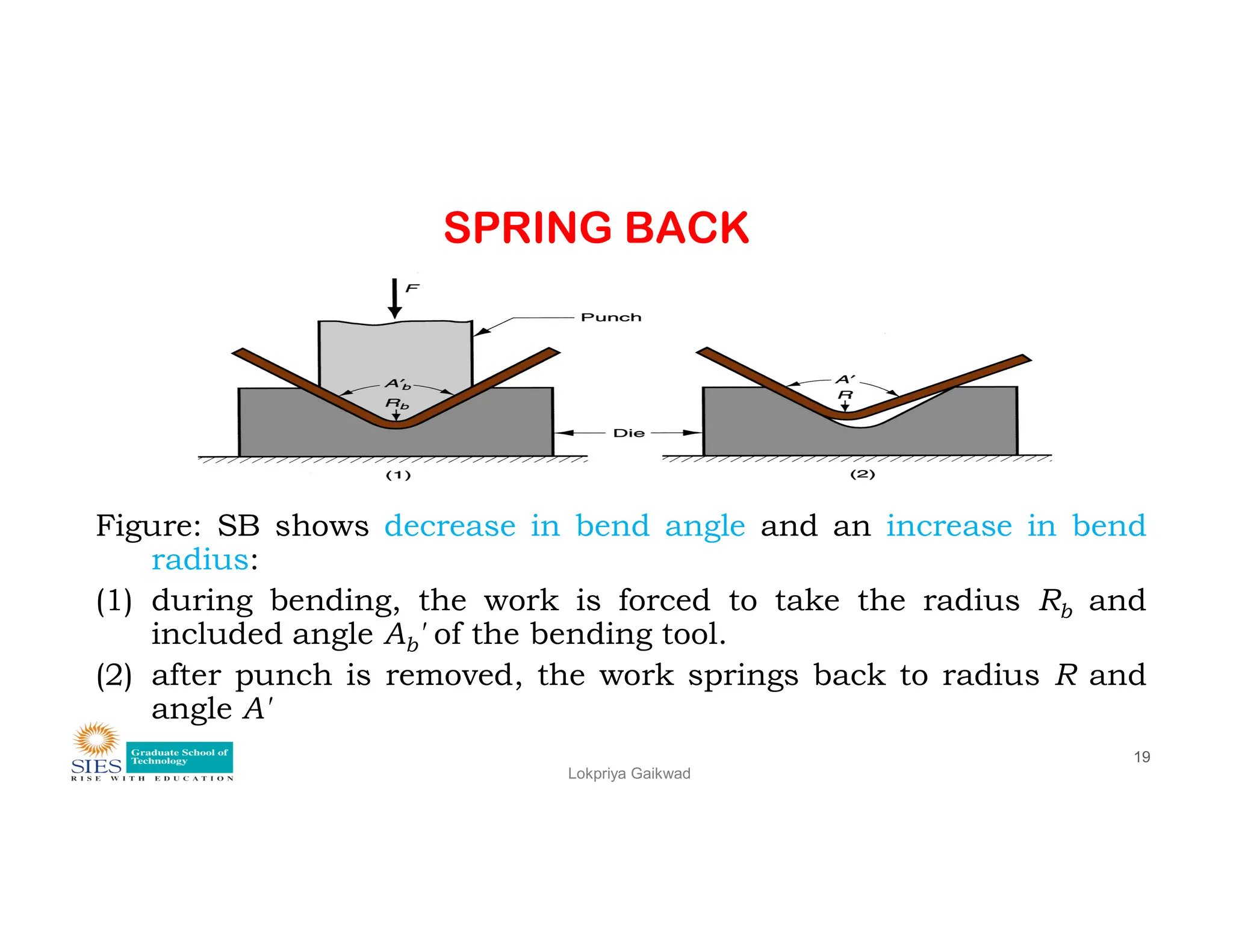
Figure:SB shows decrease in bend angle and an increase in bend
radius:
(1) during bending, the work is forced to take the radius Rb and
included angle Ab' of the bending tool.
(2) after punch is removed, the work springs back to radius R and
angle A'
20.
SPRING BACK
For lowcarbon steel, it can be 1° to 2°
medium carbon steel, it can be 3° to 4°,
phosphor bronze and spring steel = 10 to 15°.
To compensate for spring back
Punches and mating dies are made with included
Lokpriya Gaikwad
20
Punches and mating dies are made with included
angles less than required in component.
Result
Due to this, component will be bent to greater angle
than desired, but it will SB to the desired angle.
21.
SPRING BACK
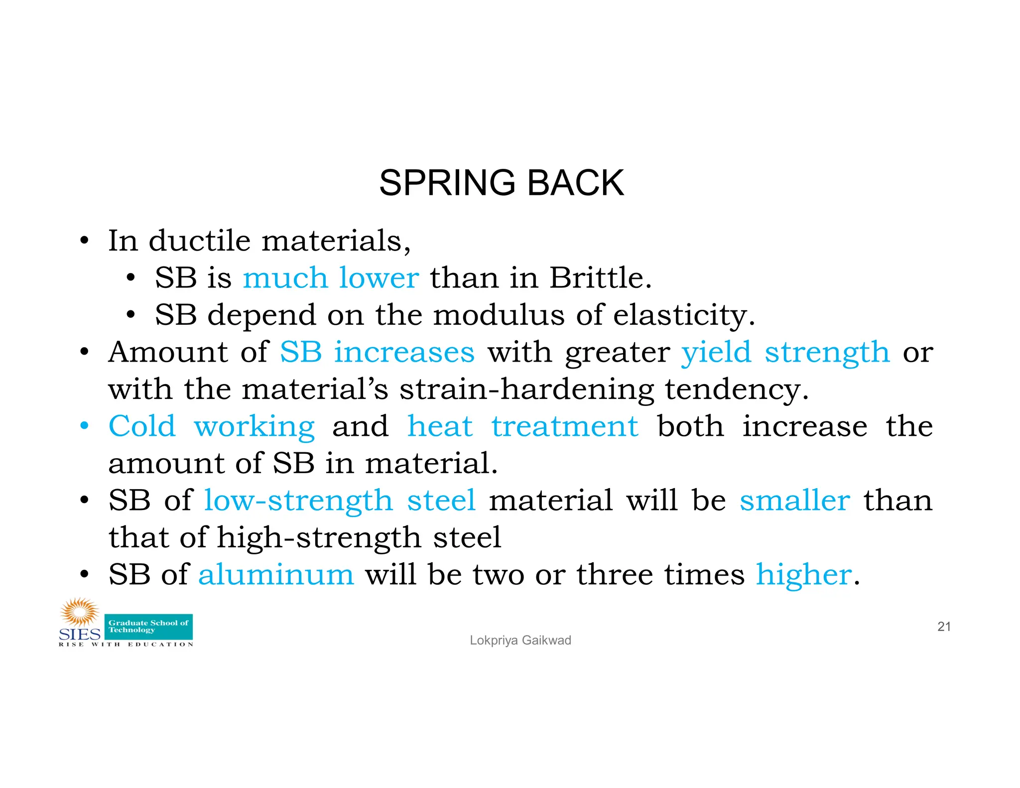
• Inductile materials,
• SB is much lower than in Brittle.
• SB depend on the modulus of elasticity.
• Amount of SB increases with greater yield strength or
with the material’s strain-hardening tendency.
Lokpriya Gaikwad
21
with the material’s strain-hardening tendency.
• Cold working and heat treatment both increase the
amount of SB in material.
• SB of low-strength steel material will be smaller than
that of high-strength steel
• SB of aluminum will be two or three times higher.
22.
SPRING BACK
For othertypes of bending, the part is overbent by an
angle equal to spring-back angle by having the face of
the punch undercut or relieved.
The values of spring back given above are for 90° bends
Lokpriya Gaikwad
22
The values of spring back given above are for 90° bends
and are usually greater for greater angles.
23.
SPRING BACK
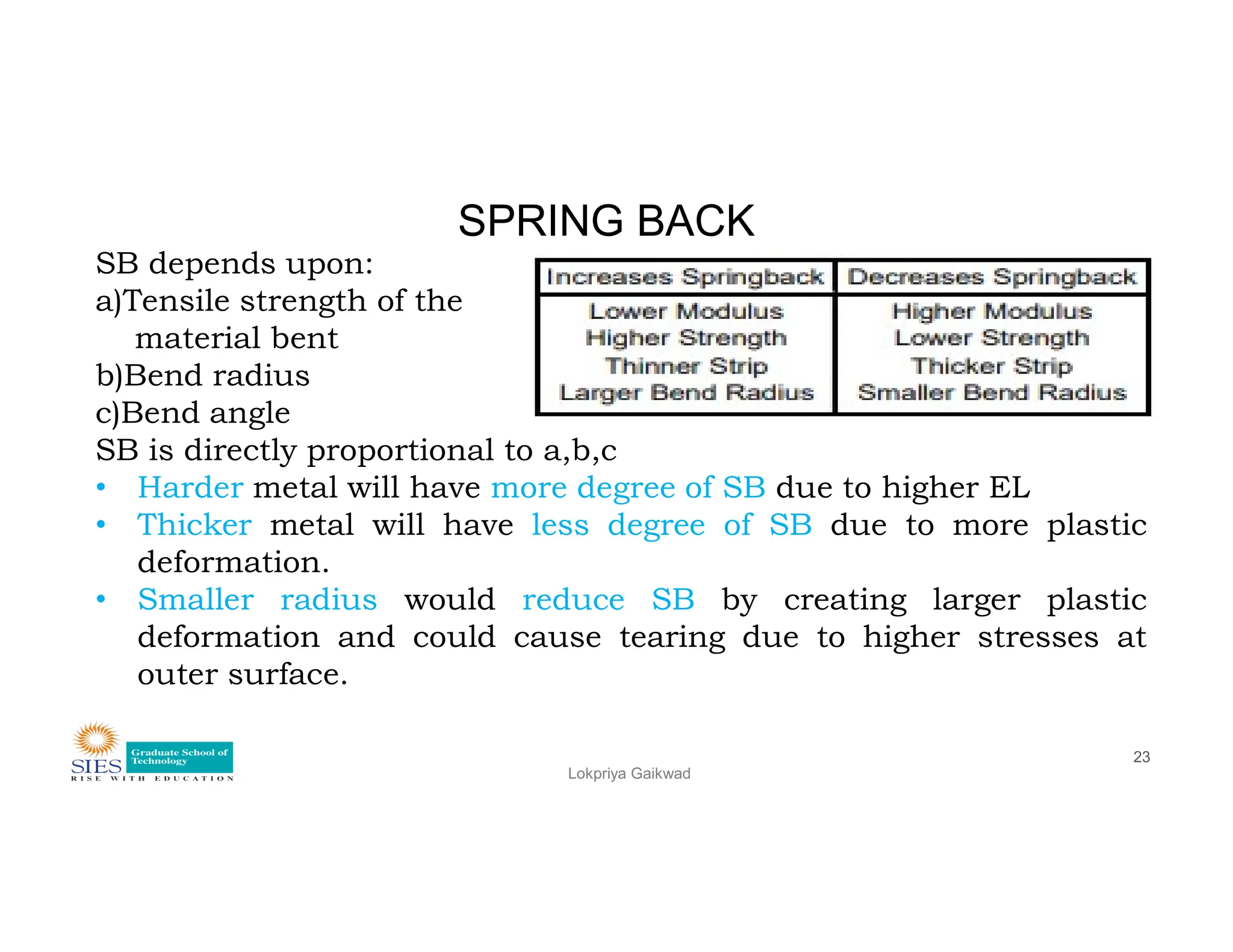
SB dependsupon:
a)Tensile strength of the
material bent
b)Bend radius
c)Bend angle
SB is directly proportional to a,b,c
• Harder metal will have more degree of SB due to higher EL
Lokpriya Gaikwad
23
• Harder metal will have more degree of SB due to higher EL
• Thicker metal will have less degree of SB due to more plastic
deformation.
• Smaller radius would reduce SB by creating larger plastic
deformation and could cause tearing due to higher stresses at
outer surface.
24.
Bending Force
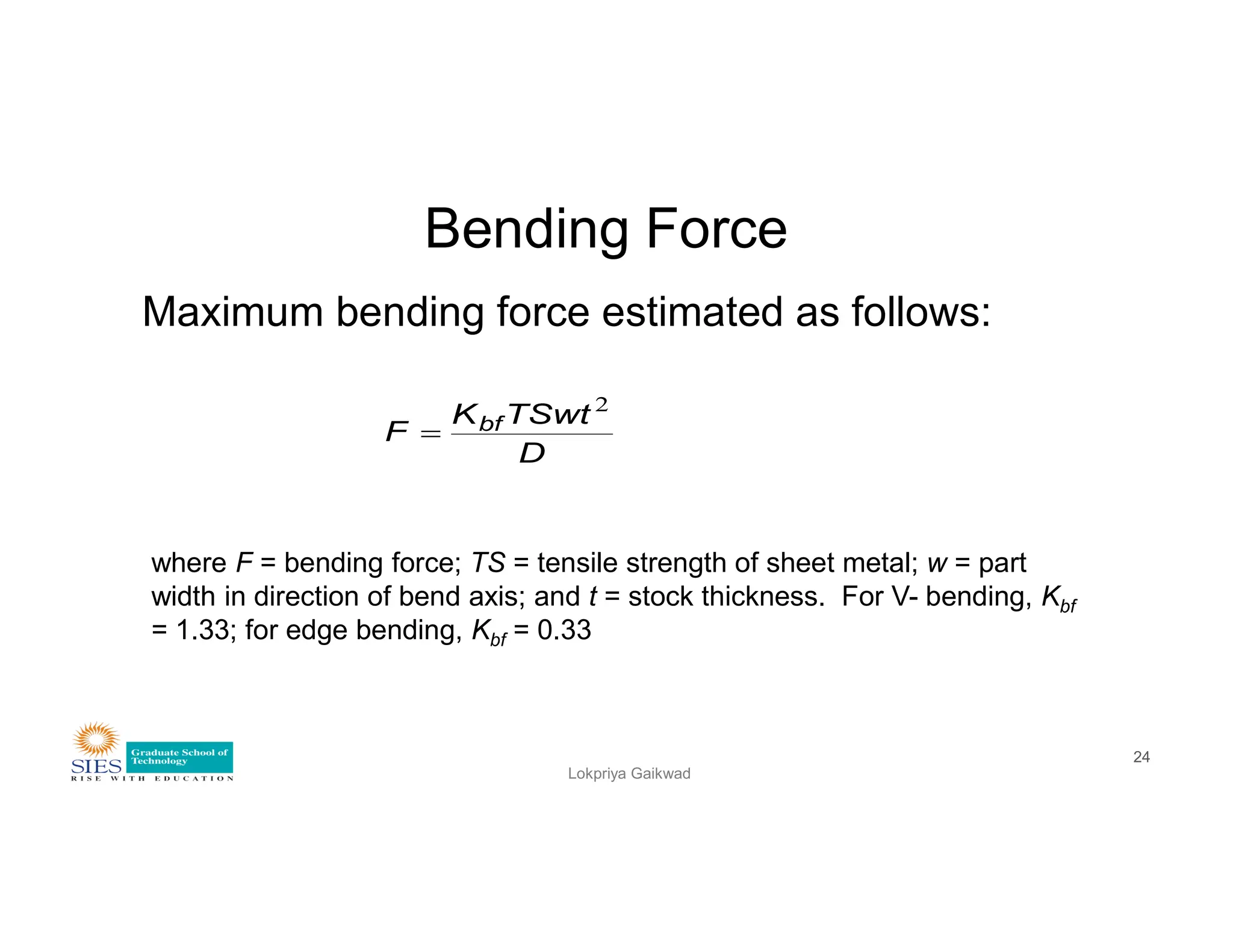
Maximum bendingforce estimated as follows:
D
TSwt
K
F bf
2
Lokpriya Gaikwad
24
where F = bending force; TS = tensile strength of sheet metal; w = part
width in direction of bend axis; and t = stock thickness. For V- bending, Kbf
= 1.33; for edge bending, Kbf = 0.33
DEFECTS IN SHEETMETAL BENDING
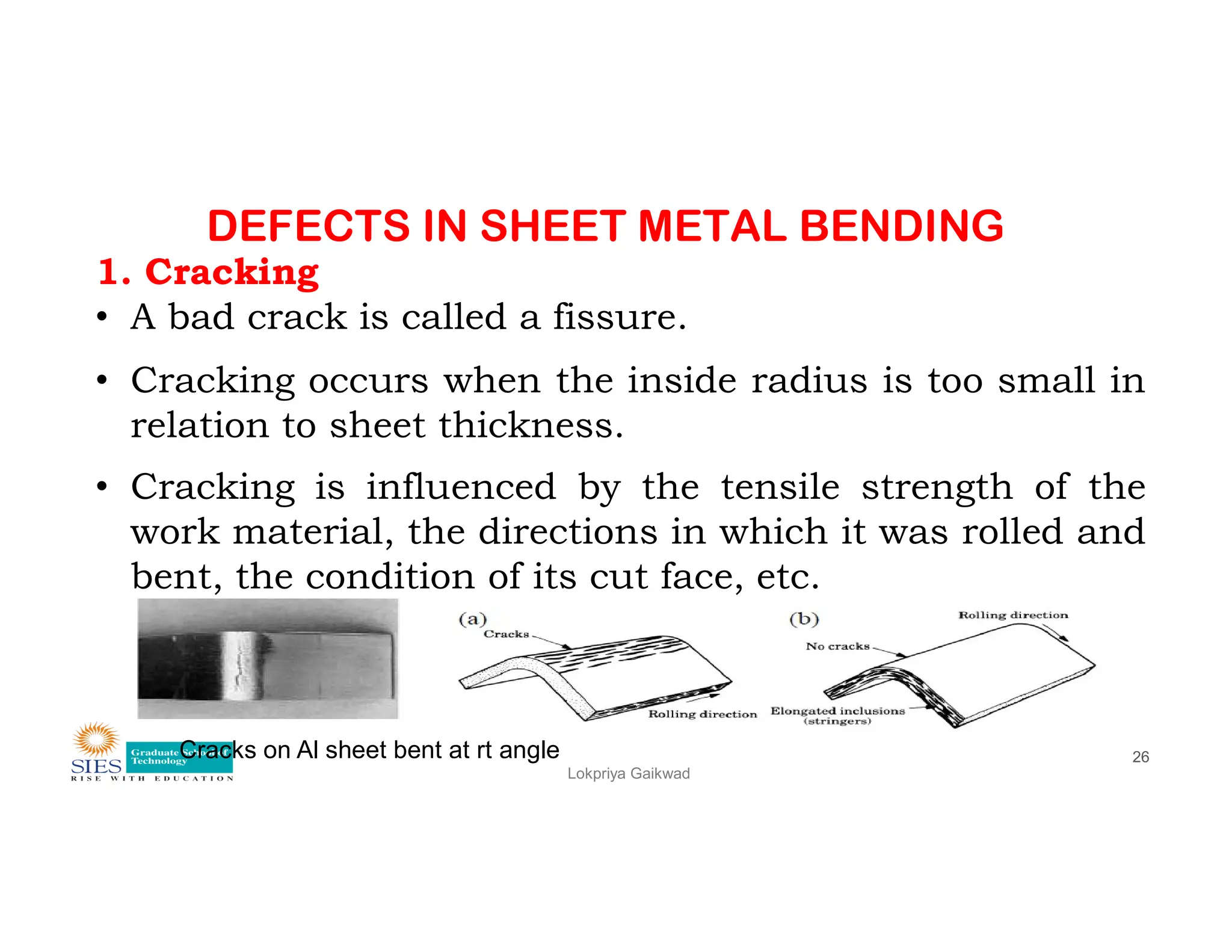
1. Cracking
• A bad crack is called a fissure.
• Cracking occurs when the inside radius is too small in
relation to sheet thickness.
• Cracking is influenced by the tensile strength of the
Lokpriya Gaikwad
26
• Cracking is influenced by the tensile strength of the
work material, the directions in which it was rolled and
bent, the condition of its cut face, etc.
Cracks on Al sheet bent at rt angle
27.
DEFECTS IN SHEETMETAL BENDING
Cracking
Following precautions are observed to prevent cracking.
1. Bend work with the sheared side (lustrous side) facing
outward.
2. Pay attention to the direction, the work material is rolled.
The work is apt to crack when it is bent in parallel with the
Lokpriya Gaikwad
27
direction of roll.
3. In case of aluminum, the punch tip R should be greater
than the sheet thickness.
4. Material with great extensibility (high ductility) is hard to
crack.
5. Use a slow bending speed.
28.
DEFECTS IN SHEETMETAL BENDING
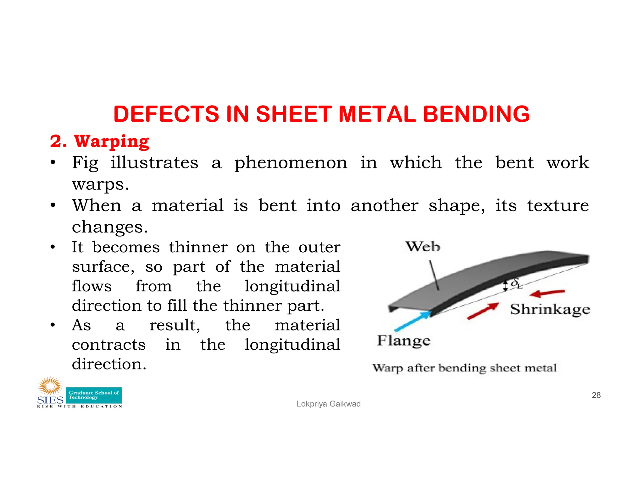
2. Warping
• Fig illustrates a phenomenon in which the bent work
warps.
• When a material is bent into another shape, its texture
changes.
• It becomes thinner on the outer
Lokpriya Gaikwad
28
• It becomes thinner on the outer
surface, so part of the material
flows from the longitudinal
direction to fill the thinner part.
• As a result, the material
contracts in the longitudinal
direction.
29.
DEFECTS IN SHEETMETAL BENDING
Warping
• This event occurring on the inner surface, together
with the force on the outer surface, causes the bent
work to warp in the longitudinal direction.
• This phenomenon varies with the type, quality, sheet
thickness and inside radius of the work.
Lokpriya Gaikwad
29
thickness and inside radius of the work.
• Warping is more severe with longer bending lengths.
• If the bending length is shorter, it can be corrected
more easily.
• In the case of long products, such corrections are
made by hand in most factories.
30.
DEFECTS IN SHEETMETAL BENDING
Marring
• The work can be marred by slippage or scraping at the
tooling joints during bending.
• Marring is a serious problem with stainless steel,
aluminum, vinyl-coated steel, and painted steel sheets
Lokpriya Gaikwad
30
aluminum, vinyl-coated steel, and painted steel sheets
which are easily scratched.
• Easily scratched material is usually coated with vinyl
before bending; however, the vinyl coating sometimes
breaks, leaving scratches on the base metal.
31.
DEFECTS IN SHEETMETAL DRAWING
Lokpriya Gaikwad
31
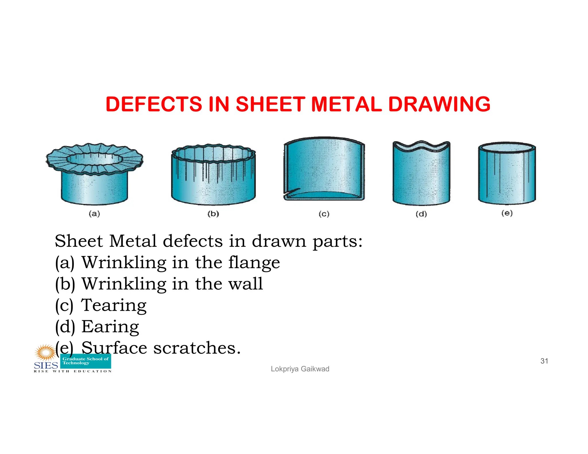
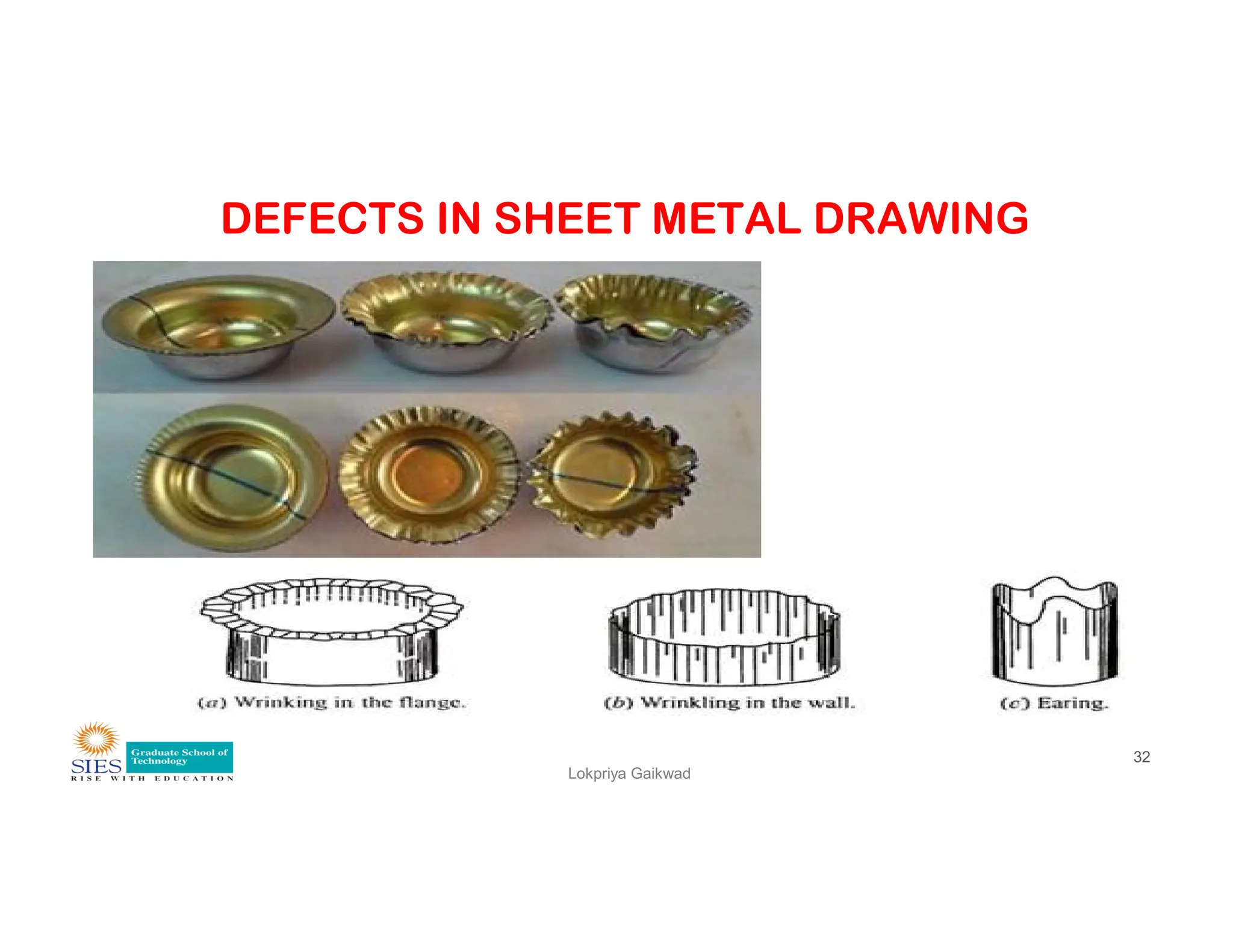
Sheet Metal defects in drawn parts:
(a) Wrinkling in the flange
(b) Wrinkling in the wall
(c) Tearing
(d) Earing
(e) Surface scratches.
DEFECTS IN SHEETMETAL DRAWING
Wrinkling
• It is a kind of buckling of the undrawn part of the
blank.
• Is is caused by the excessive compressive stresses if
the slenderness ratio is higher than a certain value.
Lokpriya Gaikwad
33
the slenderness ratio is higher than a certain value.
• This may occur in the vertical walls.
• If this defect occurs on the punch nose when drawing
a domed cup, it is known as Puckering.
34.
DEFECTS IN SHEETMETAL DRAWING
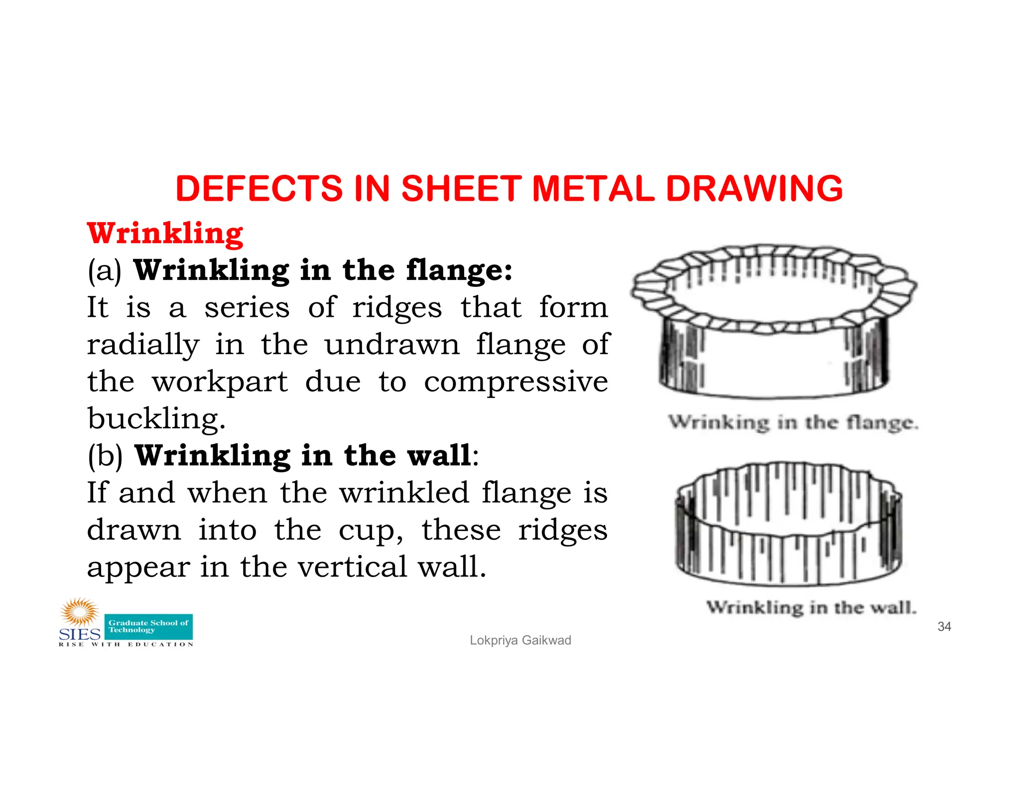
Wrinkling
(a) Wrinkling in the flange:
It is a series of ridges that form
radially in the undrawn flange of
the workpart due to compressive
Lokpriya Gaikwad
34
the workpart due to compressive
buckling.
(b) Wrinkling in the wall:
If and when the wrinkled flange is
drawn into the cup, these ridges
appear in the vertical wall.
35.
DEFECTS IN SHEETMETAL DRAWING
Tearing:
• Tearing is an open crack in the vertical wall.
• It is usually near the base of the drawn cup.
• The tearing defect usually occurs in the radius connecting
the cup bottom and the wall.
• This type of failure can also occur as the metal is pulled
Lokpriya Gaikwad
35
• This type of failure can also occur as the metal is pulled
over a sharp die corner.
• It is due to high tensile stresses that cause thinning and
failure of the metal at this location.
• Also due to the obstruction of the metal flow in the flange.
36.
DEFECTS IN SHEETMETAL DRAWING
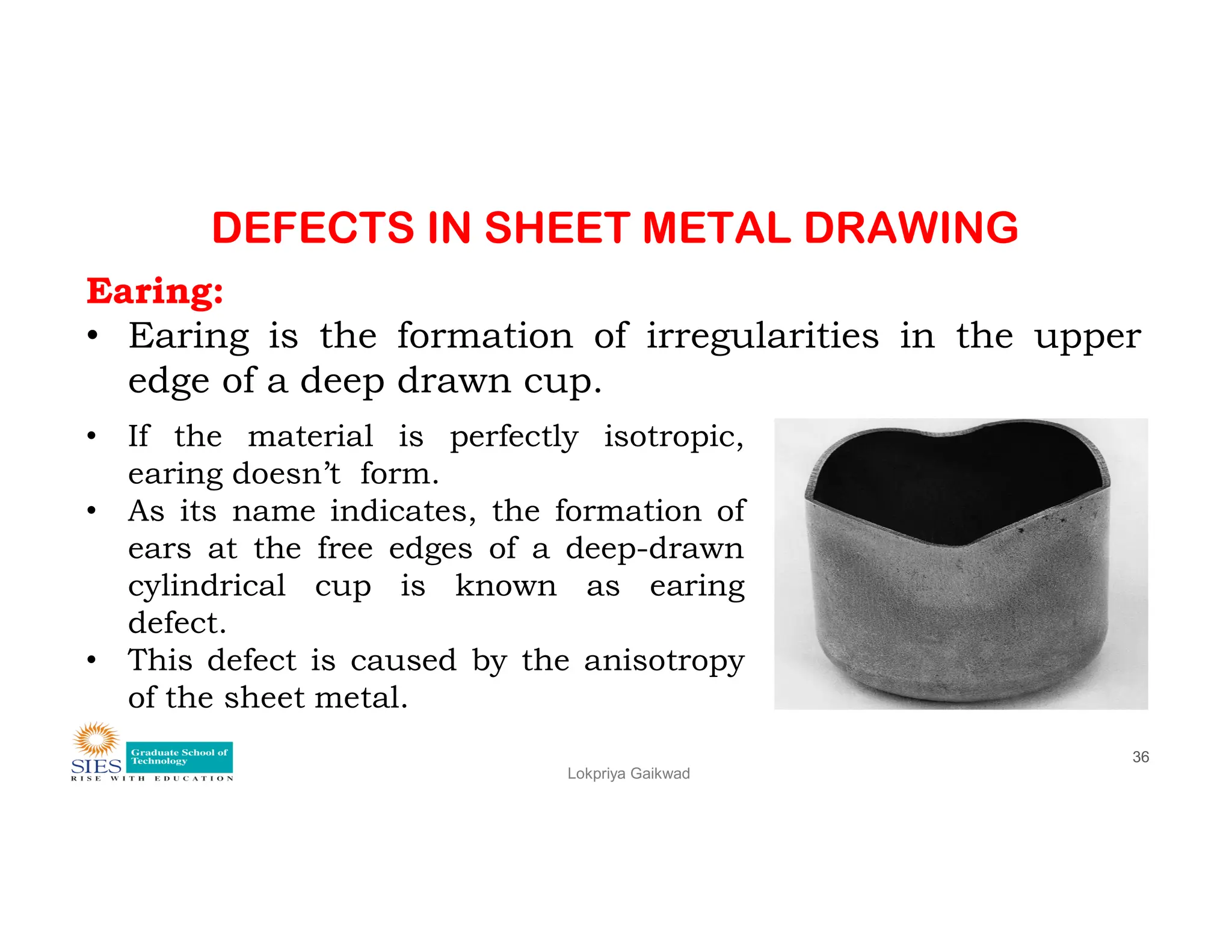
Earing:
• Earing is the formation of irregularities in the upper
edge of a deep drawn cup.
• If the material is perfectly isotropic,
earing doesn’t form.
Lokpriya Gaikwad
36
earing doesn’t form.
• As its name indicates, the formation of
ears at the free edges of a deep-drawn
cylindrical cup is known as earing
defect.
• This defect is caused by the anisotropy
of the sheet metal.
37.
DEFECTS IN SHEETMETAL DRAWING
Surface scratches:
Surface scratches can occur on the drawn part if the
punch and die are not smooth or if lubrication is not
sufficient enough.
a) Surface Marks:
These defects include draw marks, burnishing, step
Lokpriya Gaikwad
37
These defects include draw marks, burnishing, step
rings, etc. This defect is caused by improper punch-die
clearance and poor lubrication.
b) Surface Irregularities:
This defect is caused by non-uniform yielding of metal
due to non-uniform forces.


![1. SIH2025-IDEA-Presentation-Format[1].pptx](https://cdn.slidesharecdn.com/ss_thumbnails/1-251204091914-b1bb69d5-thumbnail.jpg?width=640&height=640&fit=bounds)


