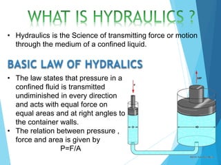
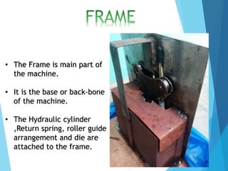
BY:-
• NISHANT DIXIT
• NAVNEET SINGH PANWAR
• MD. SAKIB JAVED
• VISHNU KUMAR
• UMASHANKAR YADAV
PROJECT GUIDE:-
MR. RACHIIT GARGA
PROJECT COORDINATOR:-
MR. ANUJ DIXIT
1. Introduction
2. Hydraulics Principle
3. Bending and it’s types
4. Hydraulic Bending
5. Components Used
6. Working
7. Advantages and Disadvantages
8. Applications
9. Future Scope
• The system that we propose is for the bending
of TMT steel bar.
• The bar is bent with the help of hydraulic
force, because the power of hydraulics is very
large, so with the help of hydraulic force we
are able to bend bar .
• When we place a bar on the hydraulic bending
machine the bar is bent by the pressure force
generated from hydraulic oil transferred by a
piston cylinder assembly to the steel bar for
bending test.
• Hydraulics is the Science of transmitting force or motion
through the medium of a confined liquid.
BASIC LAW OF HYDRALICS
• The law states that pressure in a
confined fluid is transmitted
undiminished in every direction
and acts with equal force on
equal areas and at right angles to
the container walls.
• The relation between pressure ,
force and area is given by
P=F/A
• Bending is a process by which metal is deformed by
plastically deforming the material and changing its
shape.
• Bending usually refers to deformation about one axis.
• Bending is flexible process by which many different
shape can be produced.
TYPES OF BENDS :-
• V-SHAPE BEND.
• U-SHAPE BEND.
• CIRCLE BEND.
• SQUARE BEND.
• The Bending processes which employs the power of
hydraulic fluid are known as Hydraulic bending
processes.
• These processes are of two types Hydraulic-assisted
and Hydraulic driven.
• The processes which are partially controlled by
hydraulic power are Hydraulic assisted.
• The processes which are fully controlled by hydraulic
power are Hydraulic driven processes.
• The hydraulic bending can be done manually by hand
operation of hydraulic cylinder, semi automatic and
automatic.
• Hydraulic jack
• Roller Guides and Die
• Pressure relief valve
• Return spring
• Frame
• The Hydraulic jack is operated with the help of the given handle. This jack
can be used to apply a large amount of force and pressure, due to the
presence of Hydraulic fluid.
PARTS OF HYDRAULIC BOTTLE JACK
Parts of Hydraulic Jack
by NAVNEET SINGH PANWAR
• Bending rollers are attached to the piston rod of
hydraulic jack and are movable.
• Bending die is secured in place or fixed as per the
radius facing the bending rollers.
• The Relief valve is
installed so that one
port is connected to the
pressure line and the
other port to the
reservoir.
• When pressure at the
valve’s inlet is
insufficient to overcome
spring force, the ball
remains on its seat and
the valve is closed,
preventing flow through
it.
• The Spring used for returning of
roller guide is Tension helical
spring.
• The springs are made-up of a
wire coiled in the form of a
helix.
• The cross-section of the wire of
the spring is circular.
• The helical spring is said to be
closely coiled when then spring
wire is coiled closely.
• The helix angle of such springs
is less than 10 degree.
• The Frame is main part of
the machine.
• It is the base or back-bone
of the machine.
• The Hydraulic cylinder
,Return spring, roller guide
arrangement and die are
attached to the frame.
• The bar is placed on the roller guides which are
movable here.
• The Hydraulic jack is operated with the help of
lever.
• This jack transfers pressurized Hydraulic fluid to
the piston rod.
• Due to this , the pressure force is transferred to
the guide arrangement through piston rod.
• This results in the bending of bar.
WORKING OF HYDRAULIC JACK
WORKING OF HYDRAULIC
BOTTLE JACK
by NAVNEET SINGH PANWAR
• Great efficiency and economy due to low
friction losses and high system reliability.
• Safety and overload protection by means
of relief valves.
• Low cost operation and maintenance.
• Extremely high output forces and force
multiplication by means of the "hydraulic
lever".
• Hydraulic systems are self-lubricating and
power saving.
• It can only bend-Up to 10 mm thickness.
• Heavy work is not possible.
• Because of manually operated machine,
process is not fast or continuous.
• Building construction.
• Chemical Plant and Petro-chemical
Plants etc.
• Material handling equipments.
• Stores display equipments.
• Cycle, Motorcycle frames etc.
• Electrical appliances.
• Refrigeration pipes and Boiler tubes etc.
Increasing the bending capacity from 2 tonne to more.
 Modifying the bending machine to bend tubes and
pipes by changing the roller guides.
 Semi- automation or automation of the hydraulic
bending machine by adding different components.
PROJECT Presentation(2014-15)new

PROJECT Presentation(2014-15)new

  • 1.
    BY:- • NISHANT DIXIT •NAVNEET SINGH PANWAR • MD. SAKIB JAVED • VISHNU KUMAR • UMASHANKAR YADAV PROJECT GUIDE:- MR. RACHIIT GARGA PROJECT COORDINATOR:- MR. ANUJ DIXIT
  • 2.
    1. Introduction 2. HydraulicsPrinciple 3. Bending and it’s types 4. Hydraulic Bending 5. Components Used 6. Working 7. Advantages and Disadvantages 8. Applications 9. Future Scope
  • 3.
    • The systemthat we propose is for the bending of TMT steel bar. • The bar is bent with the help of hydraulic force, because the power of hydraulics is very large, so with the help of hydraulic force we are able to bend bar . • When we place a bar on the hydraulic bending machine the bar is bent by the pressure force generated from hydraulic oil transferred by a piston cylinder assembly to the steel bar for bending test.
  • 4.
    • Hydraulics isthe Science of transmitting force or motion through the medium of a confined liquid. BASIC LAW OF HYDRALICS • The law states that pressure in a confined fluid is transmitted undiminished in every direction and acts with equal force on equal areas and at right angles to the container walls. • The relation between pressure , force and area is given by P=F/A
  • 5.
    • Bending isa process by which metal is deformed by plastically deforming the material and changing its shape. • Bending usually refers to deformation about one axis. • Bending is flexible process by which many different shape can be produced. TYPES OF BENDS :- • V-SHAPE BEND. • U-SHAPE BEND. • CIRCLE BEND. • SQUARE BEND.
  • 6.
    • The Bendingprocesses which employs the power of hydraulic fluid are known as Hydraulic bending processes. • These processes are of two types Hydraulic-assisted and Hydraulic driven. • The processes which are partially controlled by hydraulic power are Hydraulic assisted. • The processes which are fully controlled by hydraulic power are Hydraulic driven processes. • The hydraulic bending can be done manually by hand operation of hydraulic cylinder, semi automatic and automatic.
  • 7.
    • Hydraulic jack •Roller Guides and Die • Pressure relief valve • Return spring • Frame
  • 8.
    • The Hydraulicjack is operated with the help of the given handle. This jack can be used to apply a large amount of force and pressure, due to the presence of Hydraulic fluid.
  • 9.
    PARTS OF HYDRAULICBOTTLE JACK Parts of Hydraulic Jack by NAVNEET SINGH PANWAR
  • 10.
    • Bending rollersare attached to the piston rod of hydraulic jack and are movable. • Bending die is secured in place or fixed as per the radius facing the bending rollers.
  • 11.
    • The Reliefvalve is installed so that one port is connected to the pressure line and the other port to the reservoir. • When pressure at the valve’s inlet is insufficient to overcome spring force, the ball remains on its seat and the valve is closed, preventing flow through it.
  • 12.
    • The Springused for returning of roller guide is Tension helical spring. • The springs are made-up of a wire coiled in the form of a helix. • The cross-section of the wire of the spring is circular. • The helical spring is said to be closely coiled when then spring wire is coiled closely. • The helix angle of such springs is less than 10 degree.
  • 13.
    • The Frameis main part of the machine. • It is the base or back-bone of the machine. • The Hydraulic cylinder ,Return spring, roller guide arrangement and die are attached to the frame.
  • 14.
    • The baris placed on the roller guides which are movable here. • The Hydraulic jack is operated with the help of lever. • This jack transfers pressurized Hydraulic fluid to the piston rod. • Due to this , the pressure force is transferred to the guide arrangement through piston rod. • This results in the bending of bar.
  • 15.
    WORKING OF HYDRAULICJACK WORKING OF HYDRAULIC BOTTLE JACK by NAVNEET SINGH PANWAR
  • 16.
    • Great efficiencyand economy due to low friction losses and high system reliability. • Safety and overload protection by means of relief valves. • Low cost operation and maintenance. • Extremely high output forces and force multiplication by means of the "hydraulic lever". • Hydraulic systems are self-lubricating and power saving.
  • 17.
    • It canonly bend-Up to 10 mm thickness. • Heavy work is not possible. • Because of manually operated machine, process is not fast or continuous.
  • 18.
    • Building construction. •Chemical Plant and Petro-chemical Plants etc. • Material handling equipments. • Stores display equipments. • Cycle, Motorcycle frames etc. • Electrical appliances. • Refrigeration pipes and Boiler tubes etc.
  • 19.
    Increasing the bendingcapacity from 2 tonne to more.  Modifying the bending machine to bend tubes and pipes by changing the roller guides.  Semi- automation or automation of the hydraulic bending machine by adding different components.