Downloaded 716 times

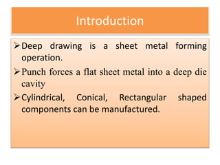
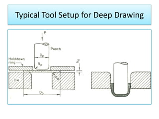
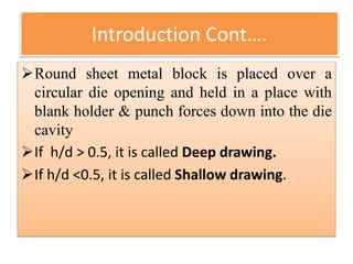
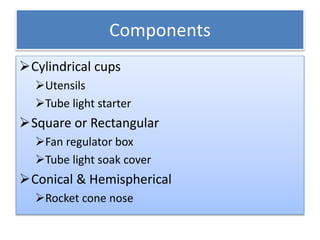
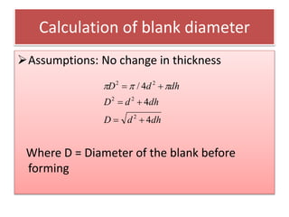
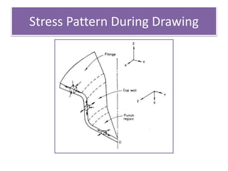
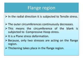
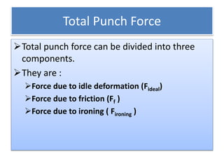
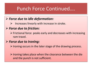
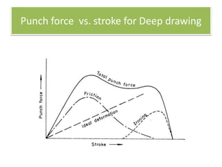
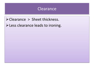
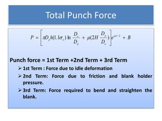
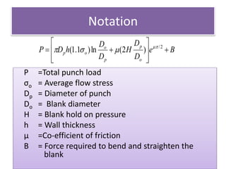
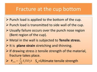
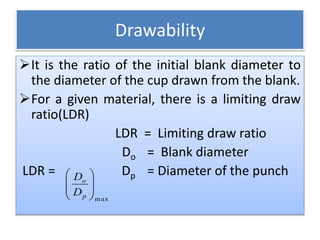
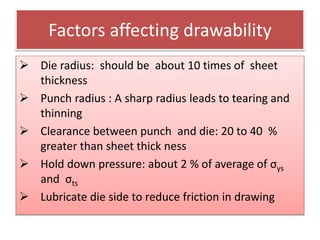
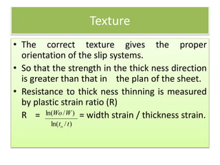
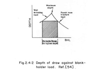
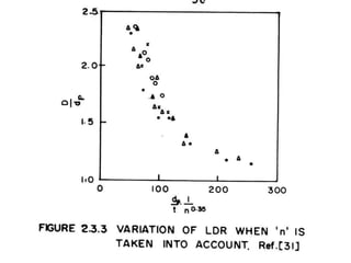
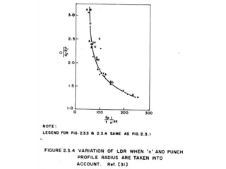
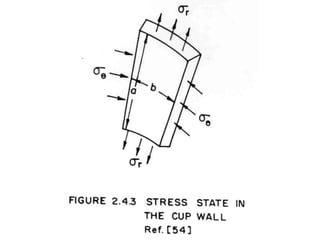
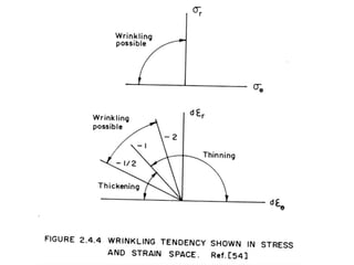
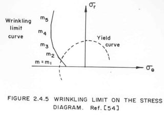
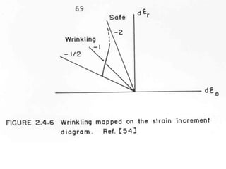
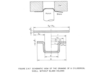
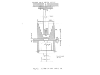
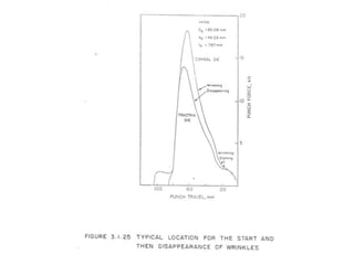
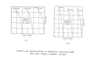
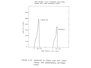
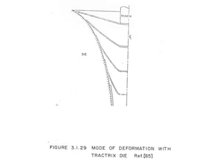


This document discusses deep drawing, a sheet metal forming process where a punch is used to push a flat sheet into a die cavity. It describes the typical tool setup, components made via deep drawing like cups and conical shapes, and calculations for blank diameter. Stress patterns in different regions during drawing are explained. Factors affecting drawability and defects in formed components like wrinkling and bottom fracture are also summarized. Formulas for total punch force and drawability ratio are provided. Methods to improve drawability like redrawing and controlling texture are outlined.


