Downloaded 915 times


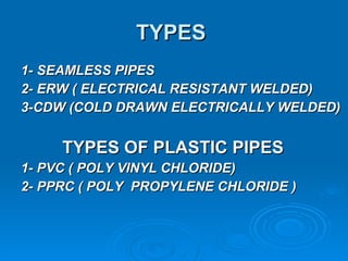
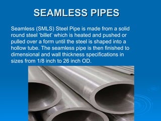
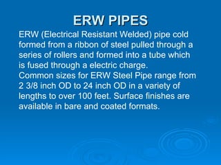
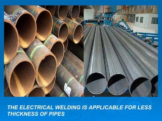
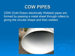
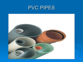
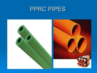
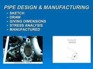
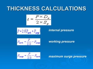


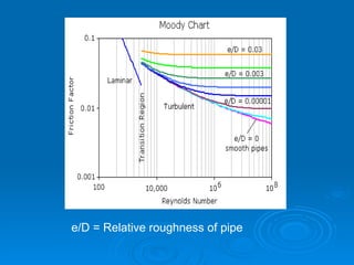
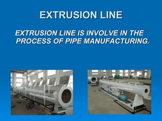
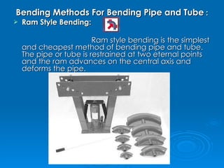
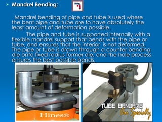
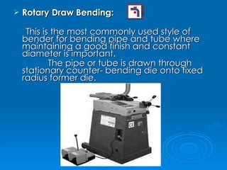
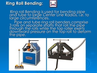

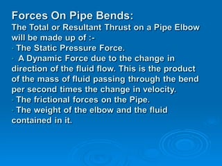
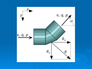
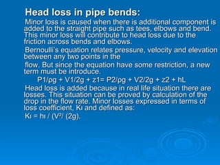
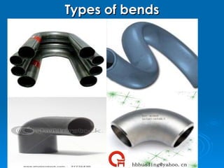
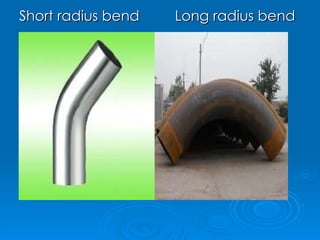
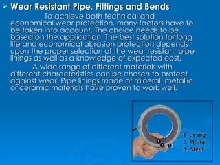
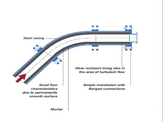
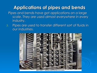
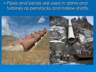
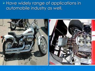
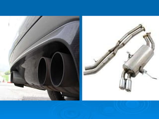
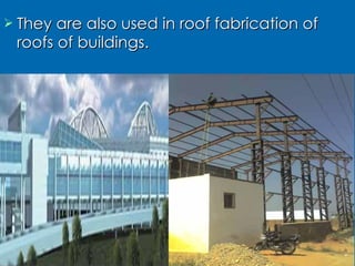

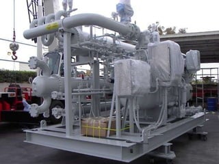
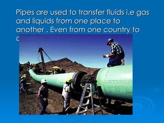

Pipes are used to transport liquids and gases and are made from various materials like steel, plastic, copper, etc. Common pipe types include seamless, ERW, and CDW pipes. Pipes are designed based on thickness calculations to withstand internal and working pressures. Bends in pipes are formed using methods like ram bending and mandrel bending. Forces like pressure, mass flow, and velocity cause stresses on bends. Head loss occurs in bends due to friction and is quantified using loss coefficients. Pipes and bends have wide applications in industries, buildings, households, and infrastructure.


![5G Explained! A High Level Overview [Introduction]](https://cdn.slidesharecdn.com/ss_thumbnails/5gexplainedahighleveloverview-260119165306-cc137a3e-thumbnail.jpg?width=640&height=640&fit=bounds)


