Downloaded 251 times

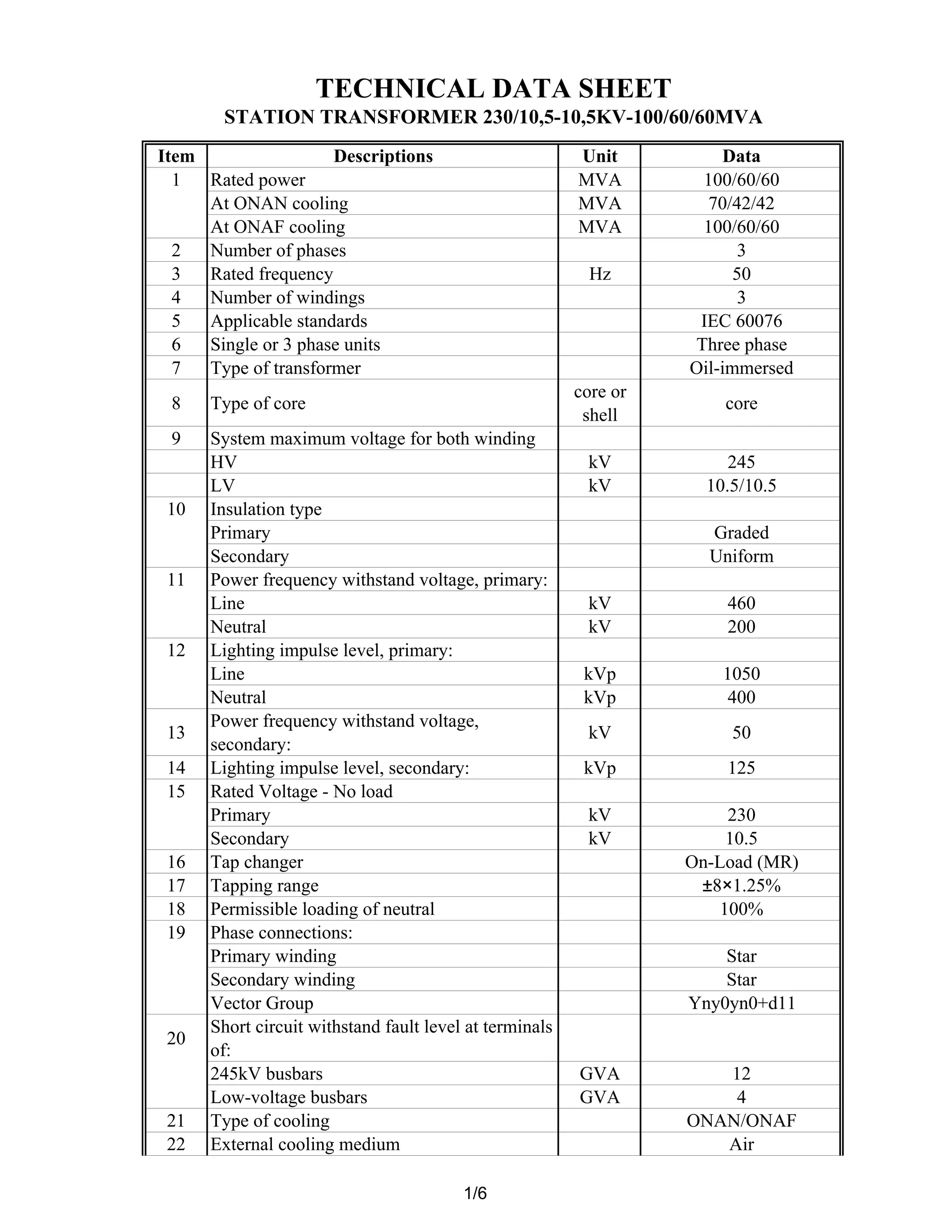
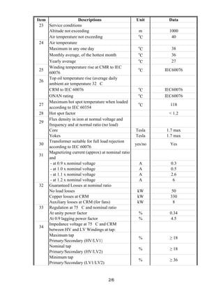
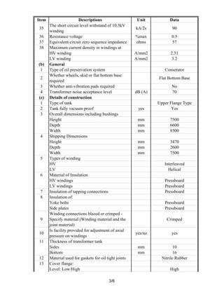
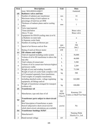
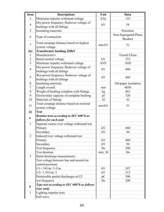

This document provides technical specifications for a three-phase power transformer. Key details include: - Rated power of 100/60/60 MVA at ONAN and ONAF cooling - Three winding phases, 50 Hz frequency - Oil-immersed core type transformer meeting IEC 60076 standards - Primary voltage of 245 kV and secondary voltages of 10.5/10.5 kV - ON-load tap changer with ±8% range in 1.25% steps - Short circuit withstand levels of 12 GVA and 4 GVA for the high and low voltage terminals - ONAN/ONAF cooling using 14 radiators and 6 fans providing 304.2 m3/


