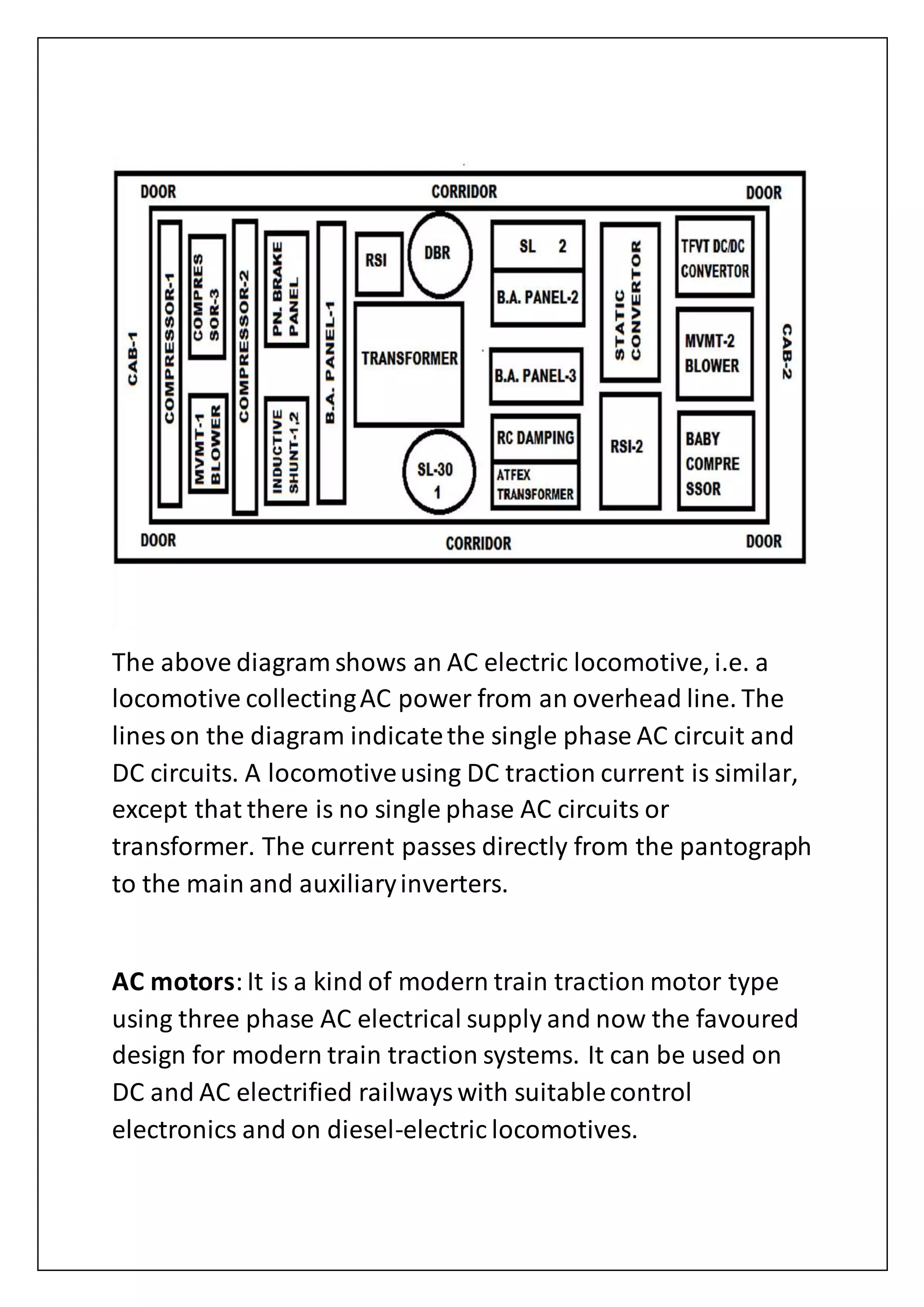
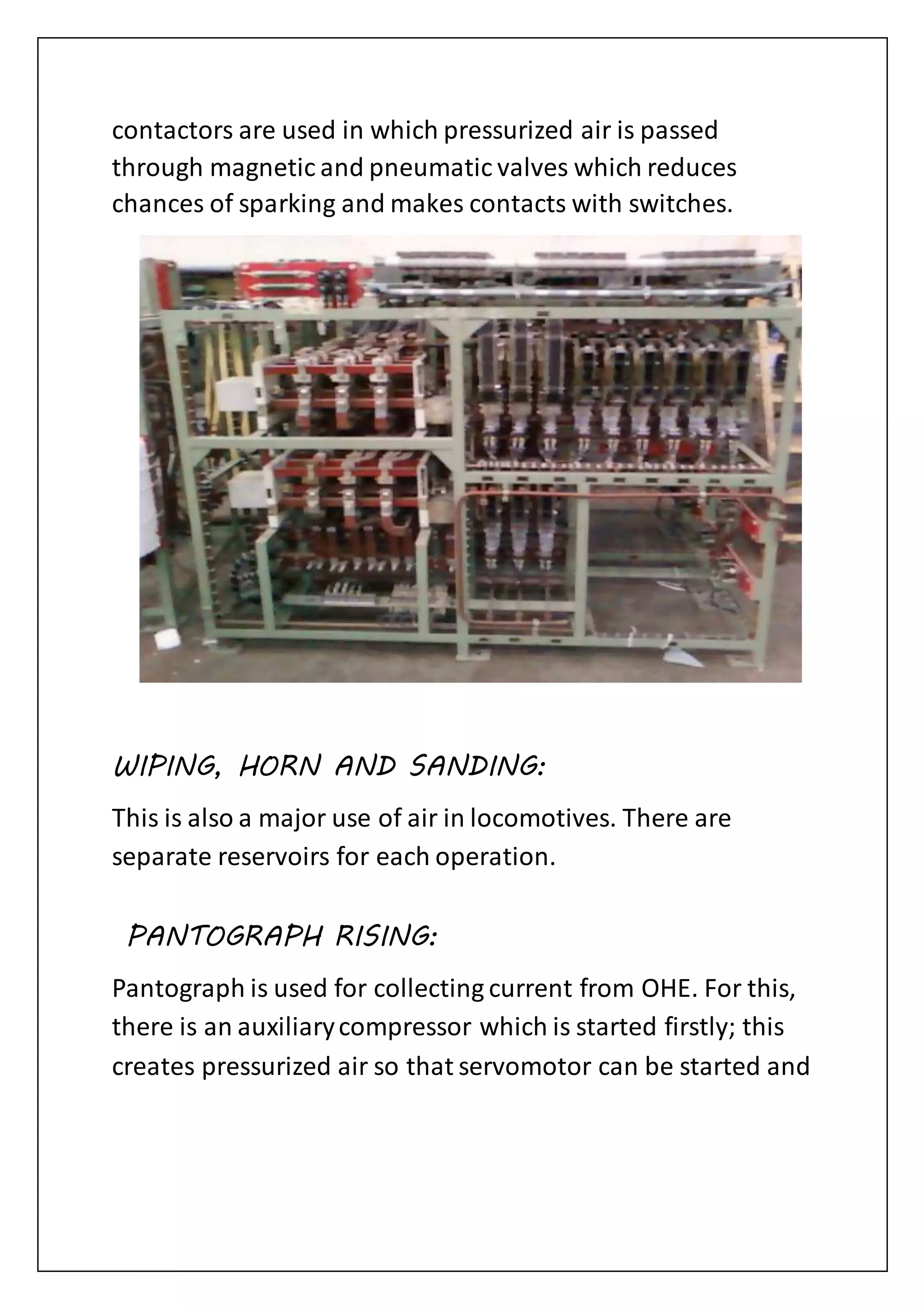
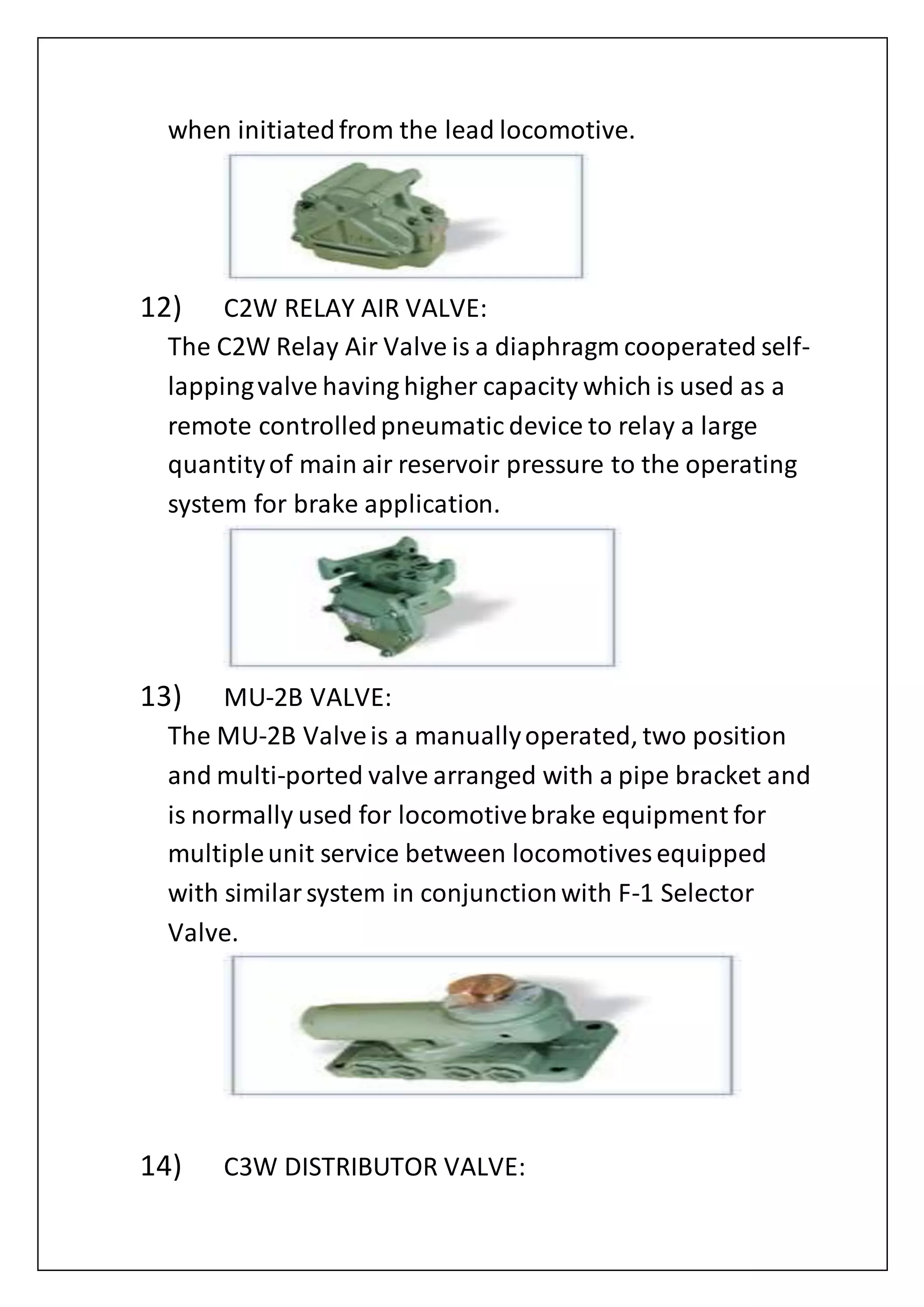
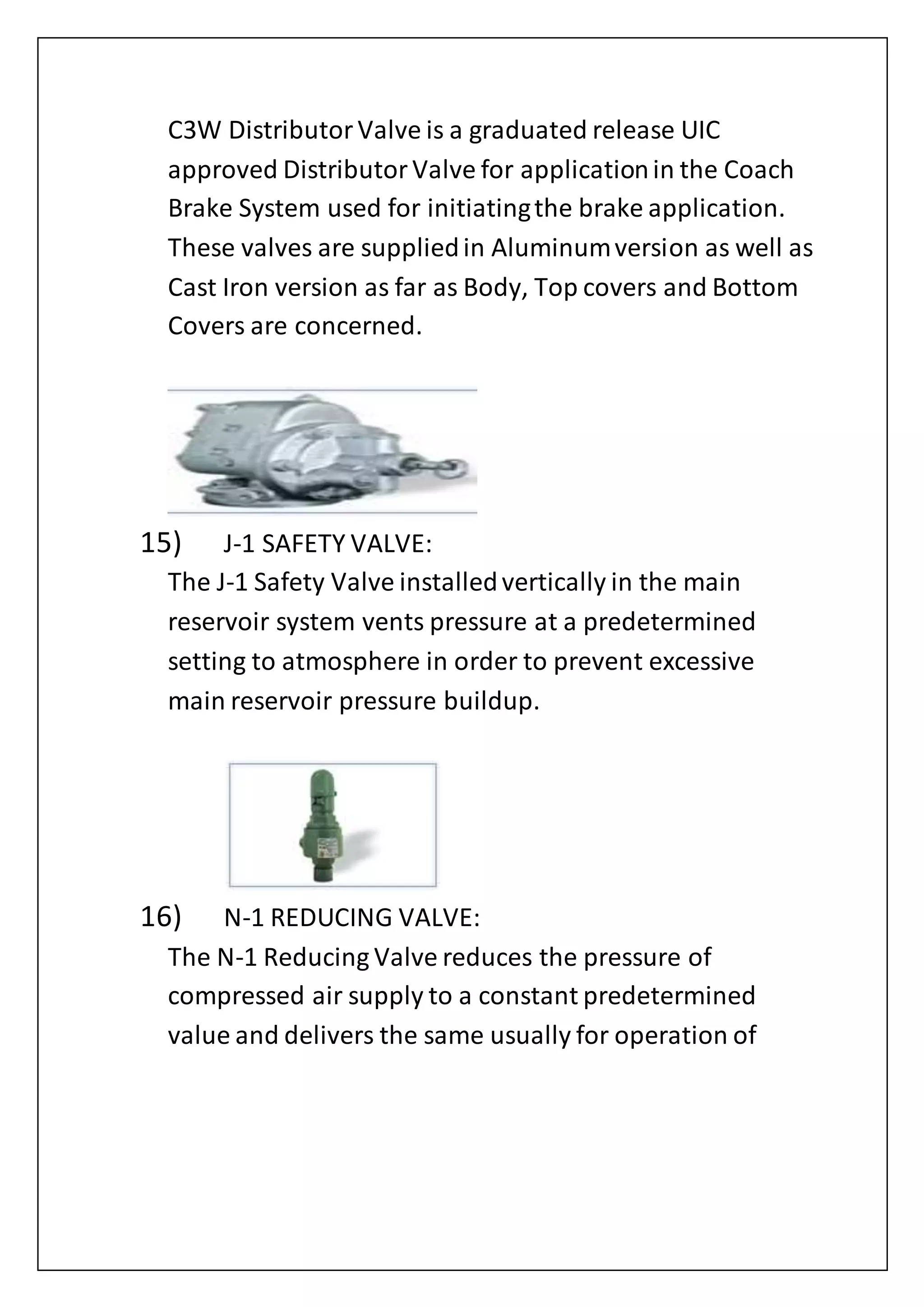
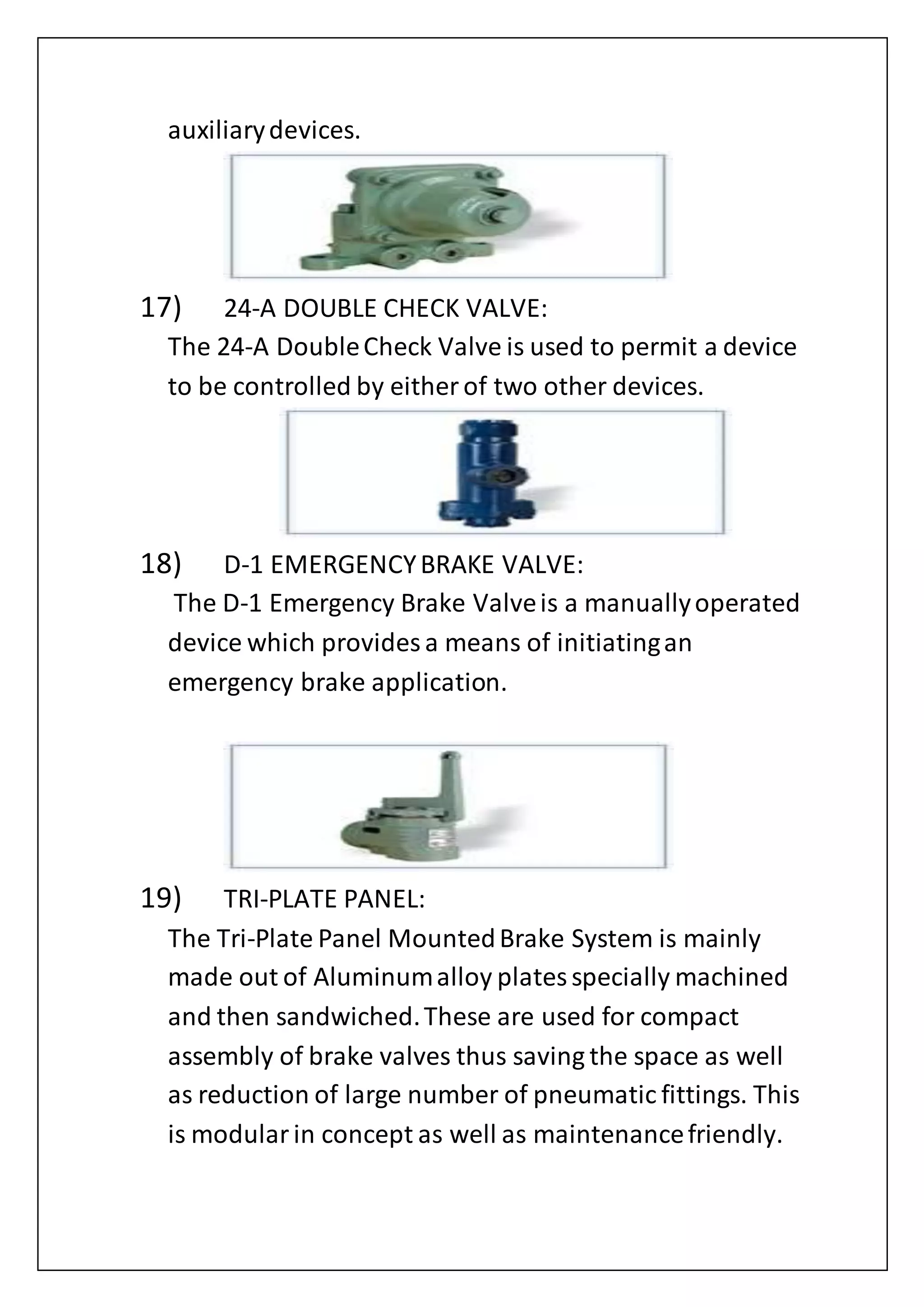
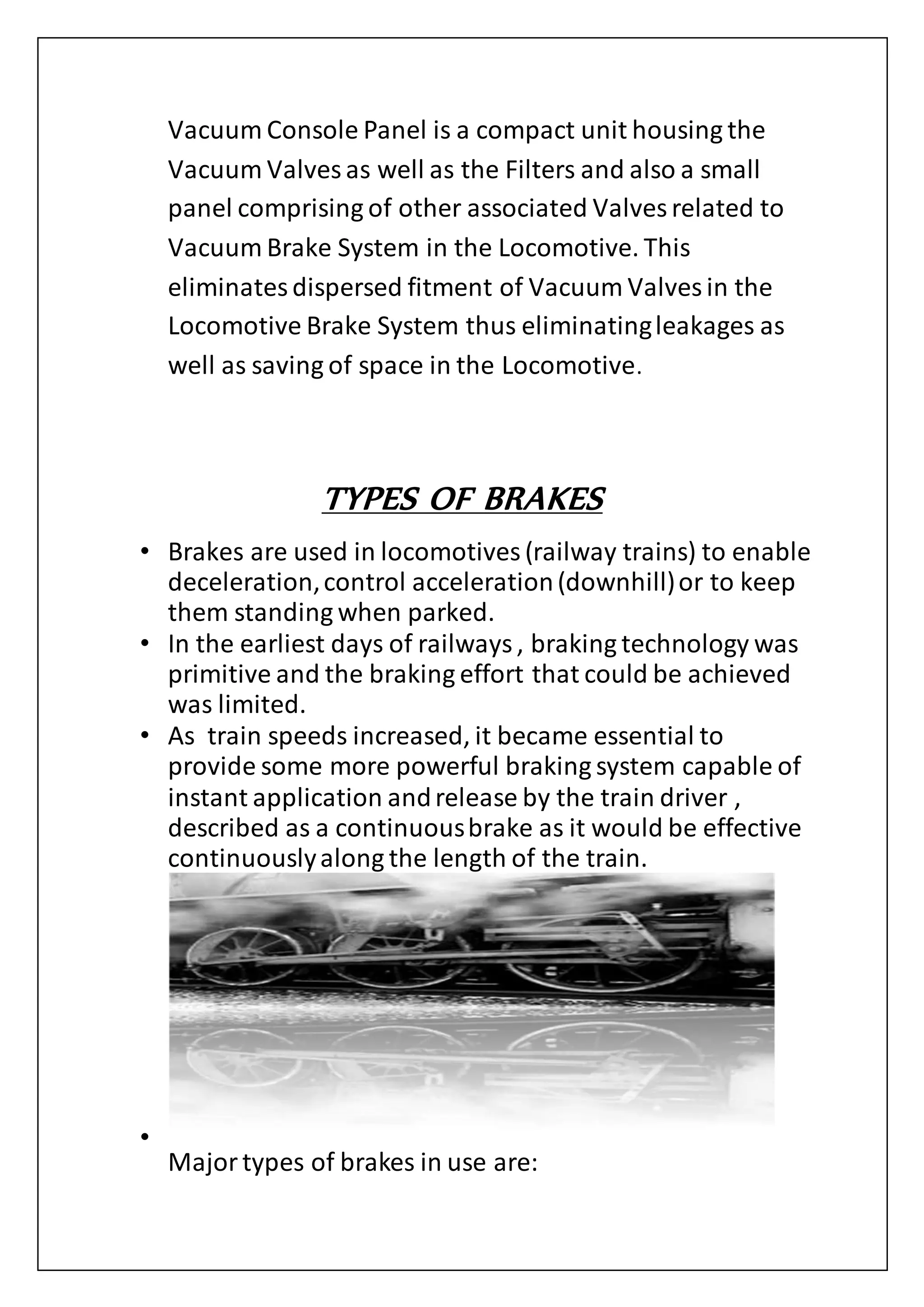
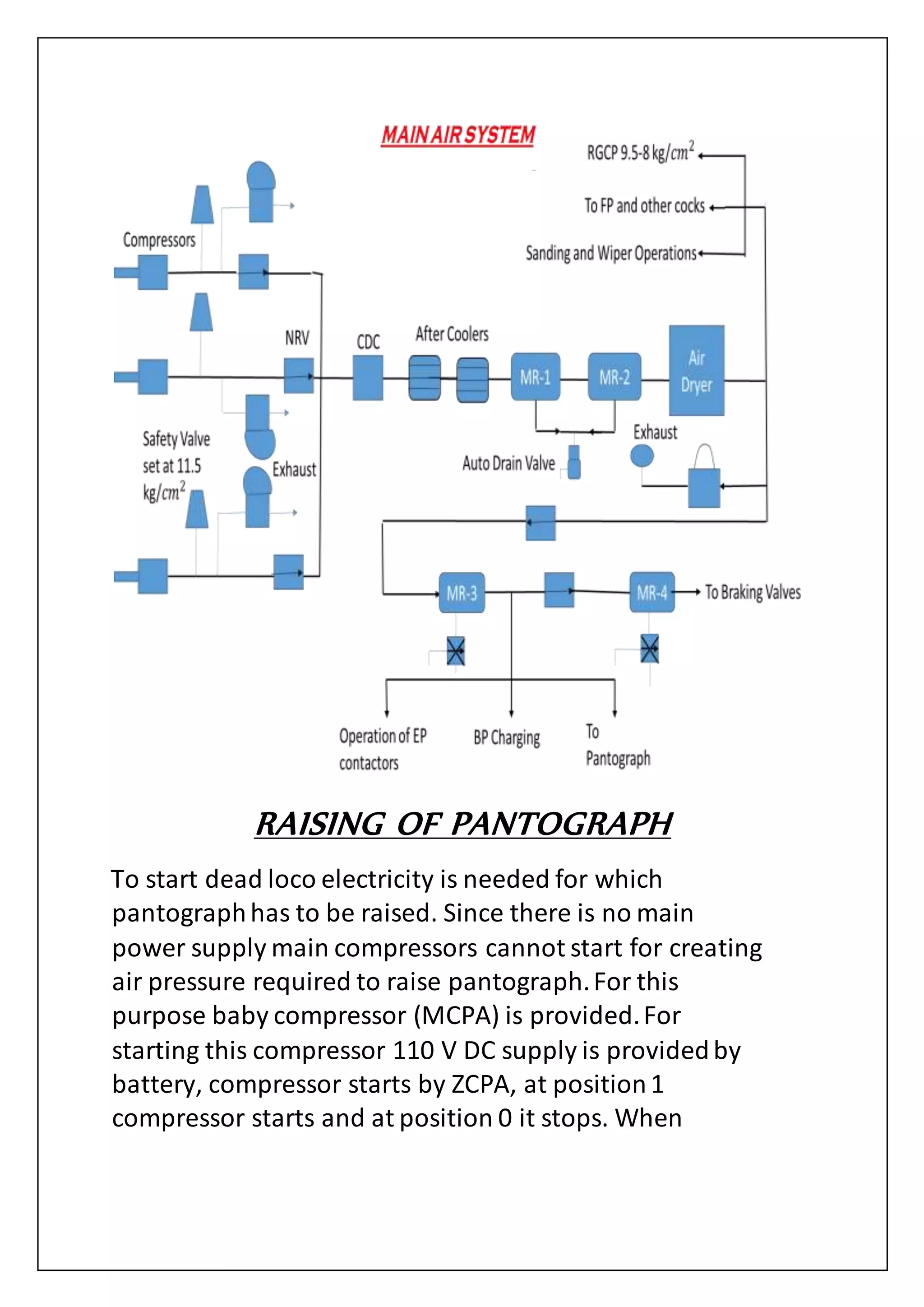
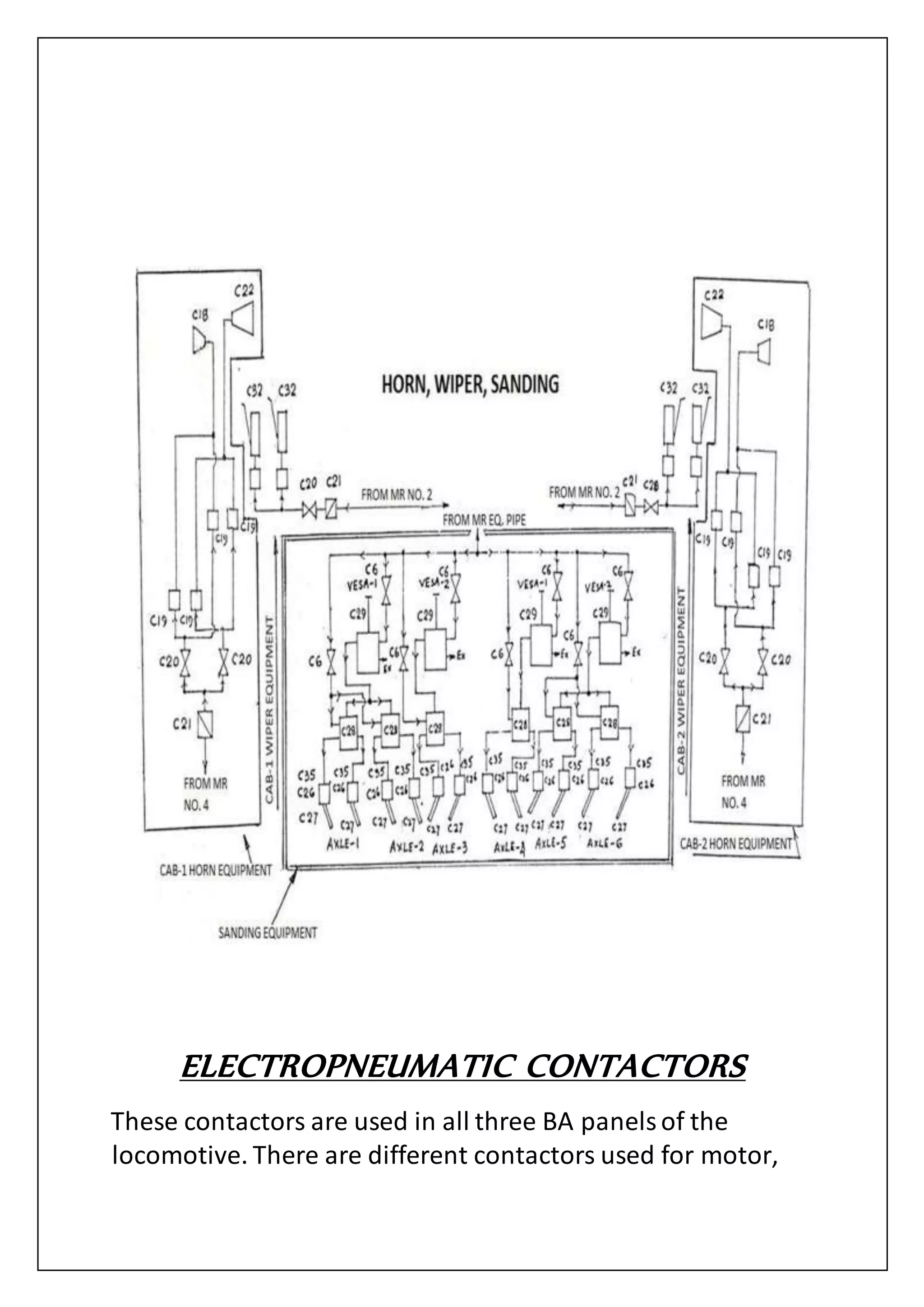
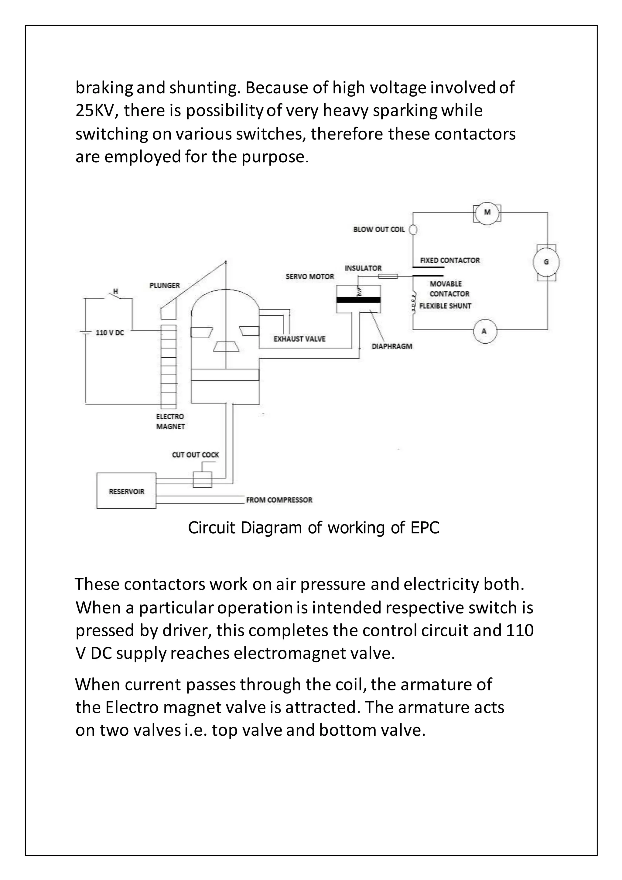
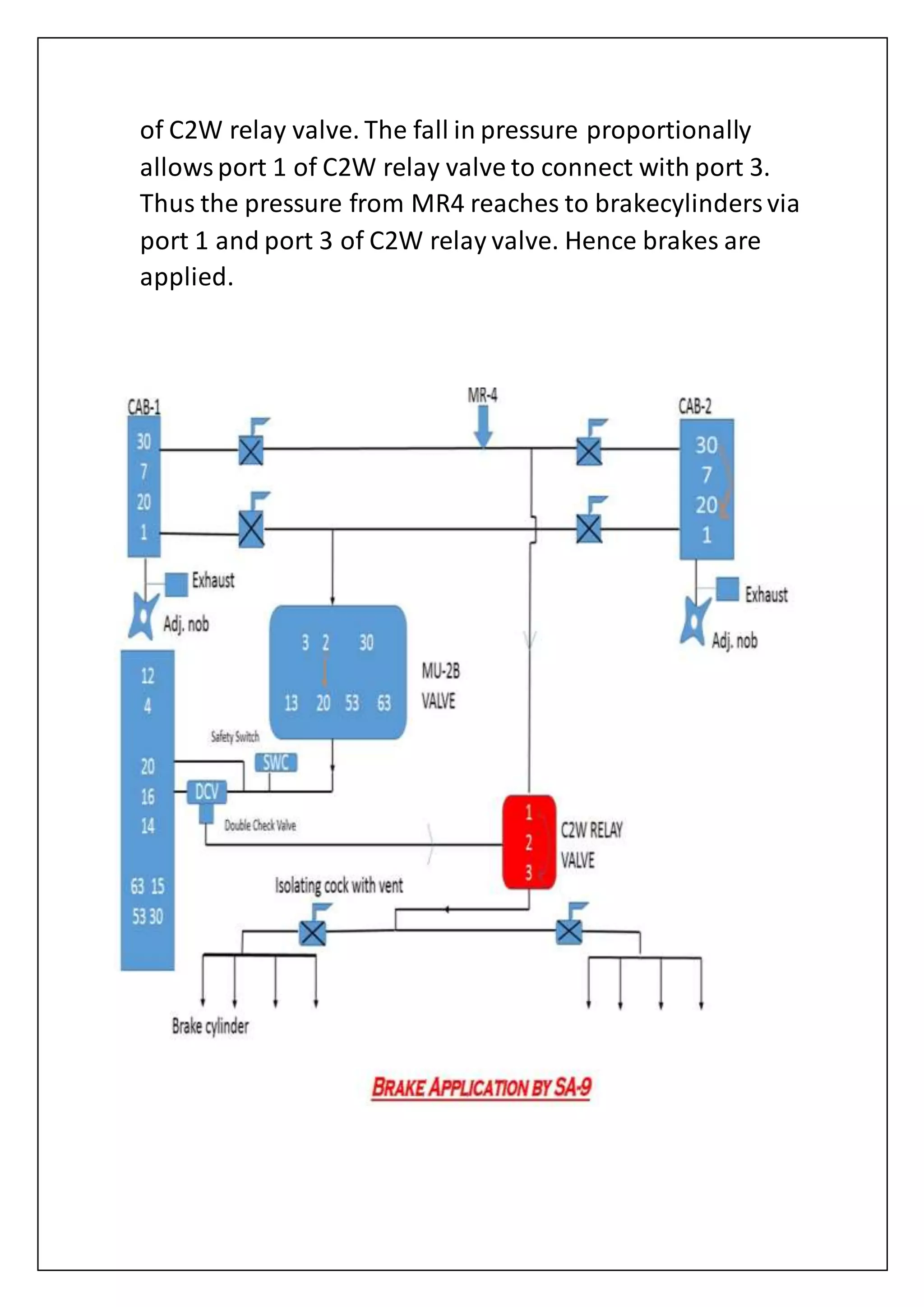
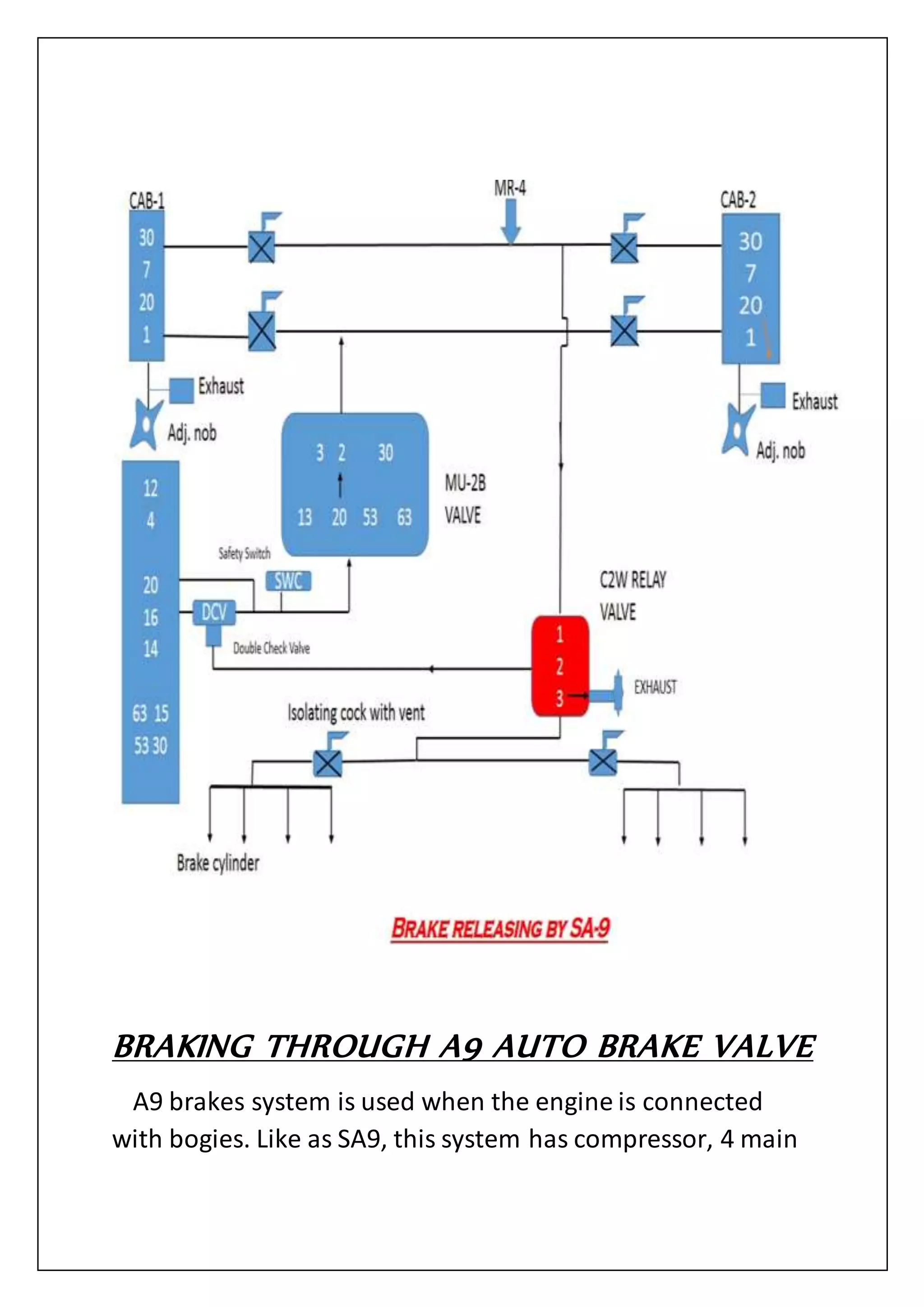
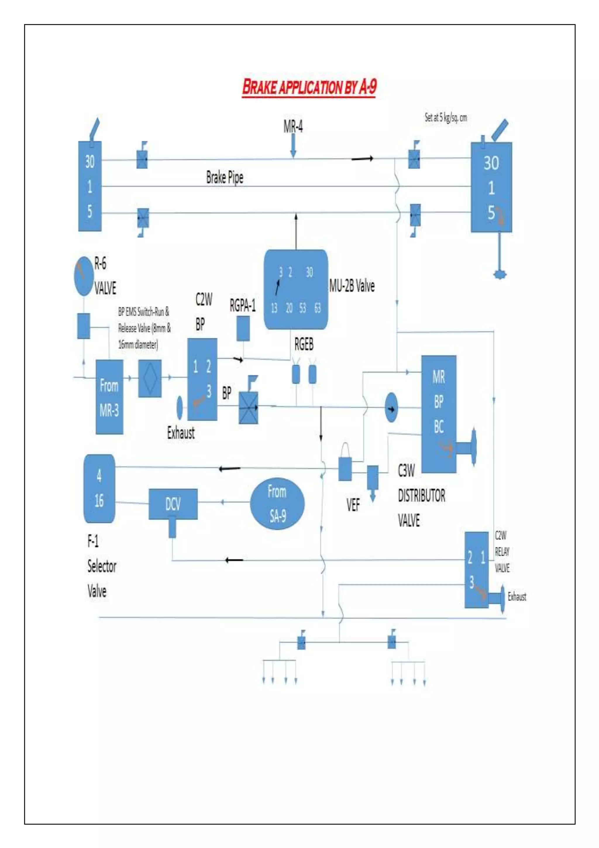
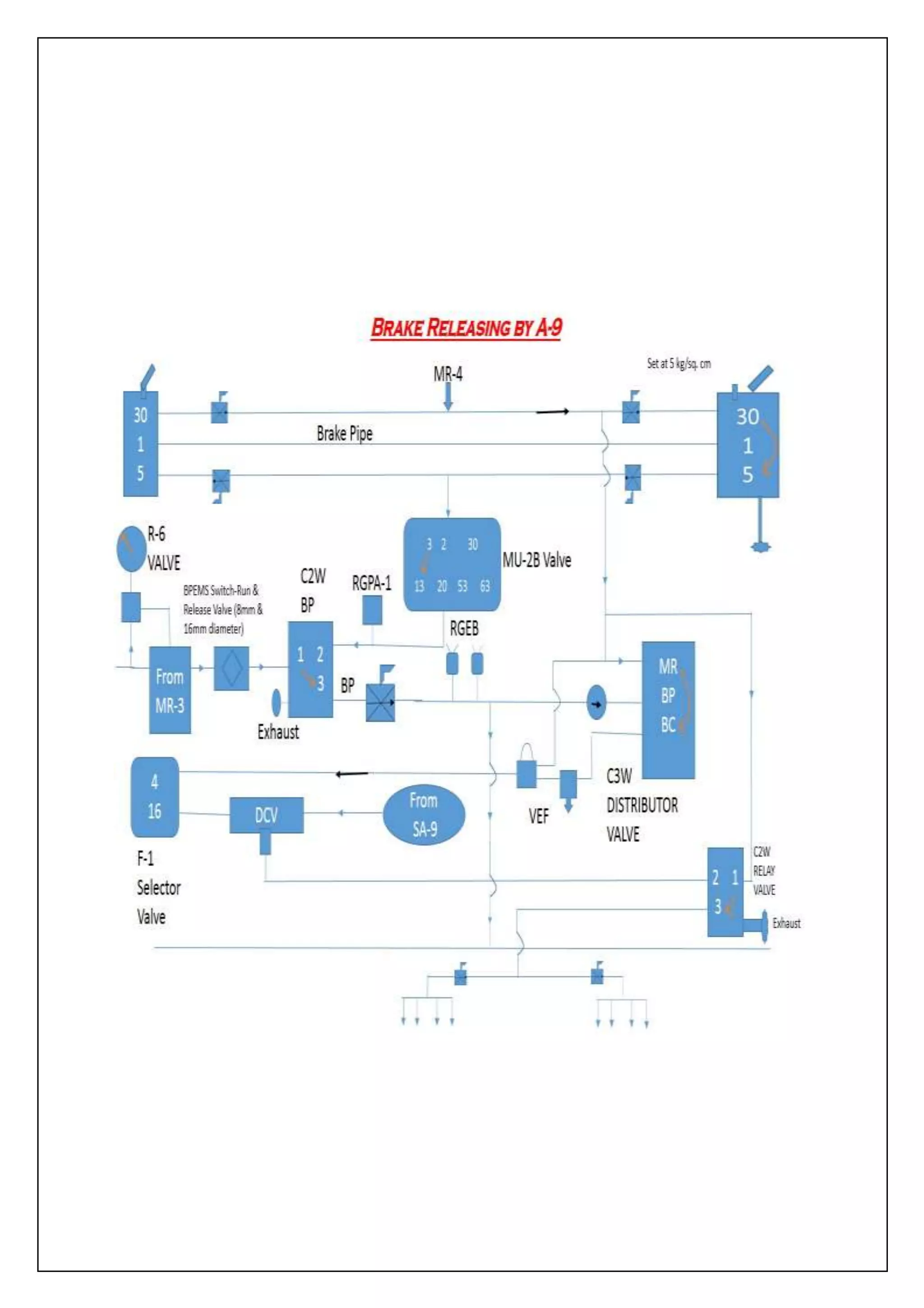
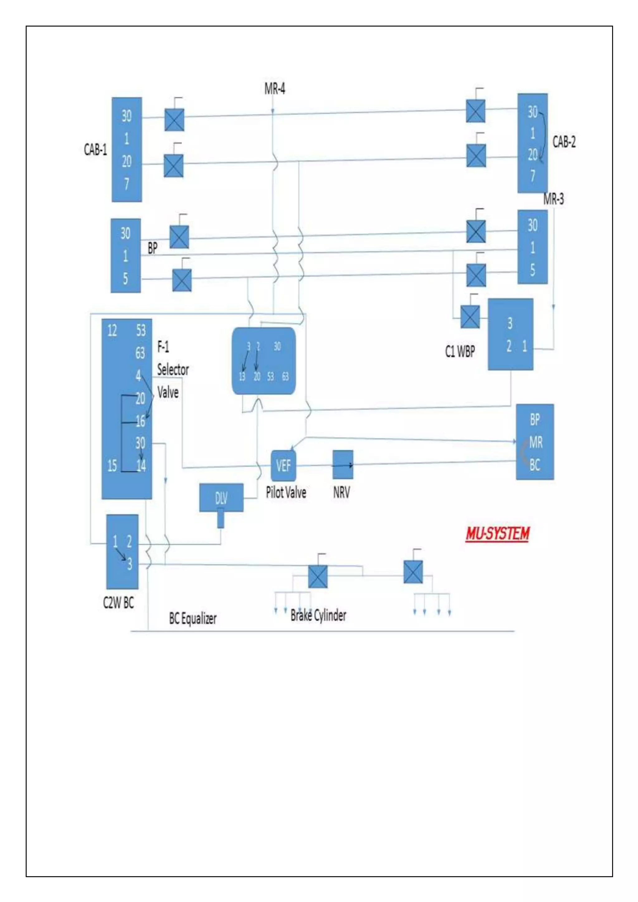
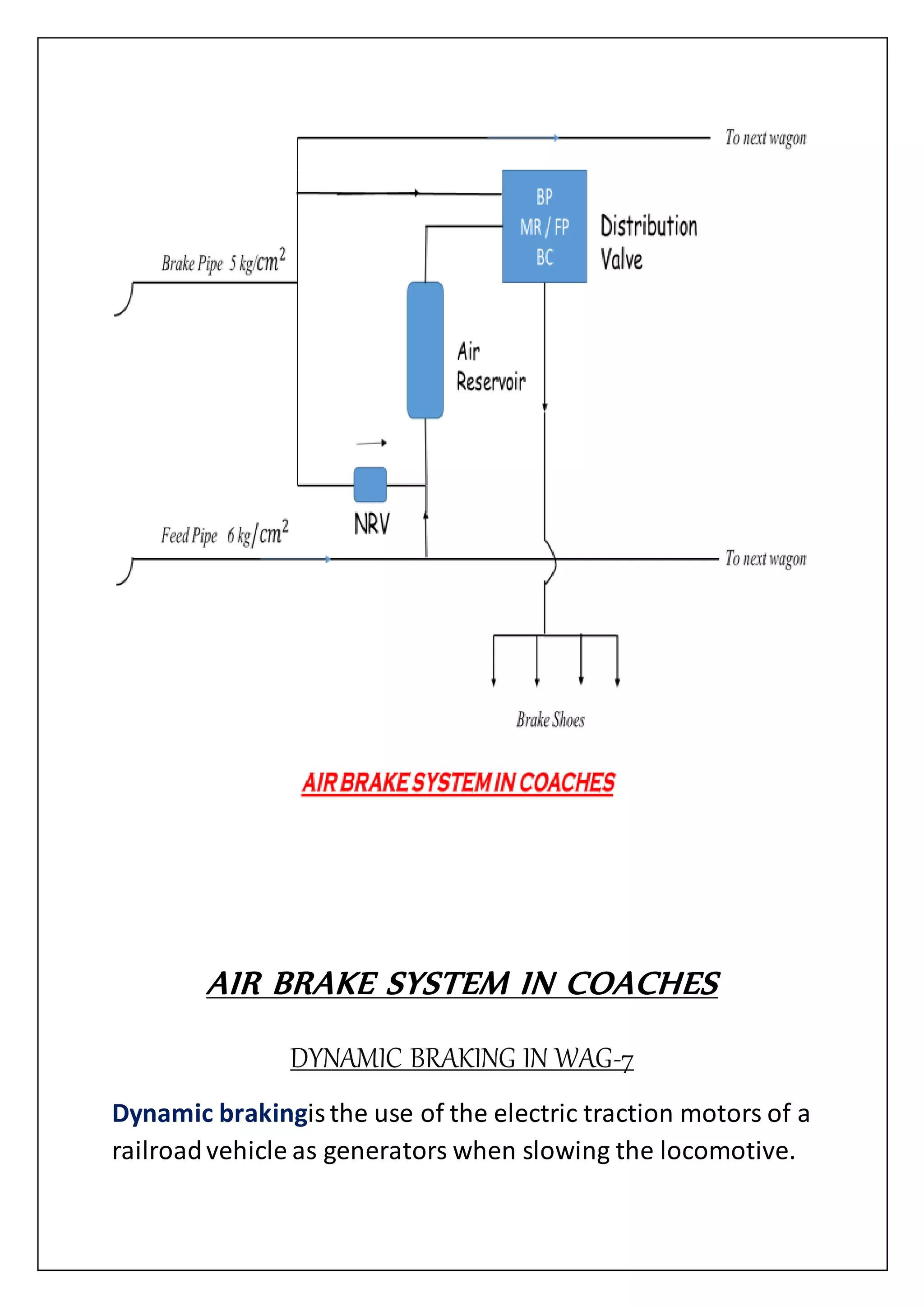
PNEUMATIC SYSTEMS IN WAG-7
SUBMITTEDTO: SUBMITTEDBY: Dr.
Dhruv Bhargav Aayush Singhal
Sr. DGM, HRD B.Tech (ME) II Year
GLA University
ACKNOWLEDGEMENT
I am extremely thankful and indebted to the numerous
BHEL engineers, who provided vital information about
the functioning of their respective departments thus
helping me to gain an overall idea of the working of the
organization.
I am highly thankful to my project guide Mr. Y.R.
Tripathi (Production Engineer, LMM) and Mr.
Bahadur Singh (Engineer, LMM) for giving me the
chance to get acquainted with various aspects of
locomotive breaking system.
Last but not the least I would like to thank my parents
and all my fellow trainees who have been a constant
source of inspiration and encouragement during my
studies and training.
CONTENTS
BHARAT HEAVY ELECTRICALS LIMITED
S.NO Topic Name Page
No.
1 BHEL –INTRODUCTION 4
2 VISION, MISSION ,VALUES 6
3 ROTATION REPORT 7
4 PRODUCTSOF BHEL Jhansi 30
5 LocomotiveDepartment(LMM) 32
6 Product of LMM 40
7 WAG-7 41
8 T.S. OF WAG-7 42
9 EQUIPMENTLAYOUT 47
10 PNEUMATIC FUNCTIONS 51
11 PNEUMATIC EQUIPMENTS 53
12 TYPE OF BRAKES 59
13 BRAKE PRINCIPLE 68
14 AIR BRAKE SYSTEM 70
15 MAIN AIR SYSTEM 75
16 RAISING OF PANTOGRAPH 77
17 HORN,WIPER AND SANDING 78
18 OPERATION OF E.P. CONTACTORS 80
19 SA-9 (APPLICATION & RELEASE) 82
20 A-9 (APPLICATION & RELEASE) 85
21 AIR BRAKE SYSTEM IN MU SYSTEM 88
22 AIR BRAKE SYSTEM in COACHES 91
23 CONCLUSION 94
24 REFRENCES 95
INTRODUCTION
Bharat Heavy Electricals Limited (BHEL) is one of the oldest
and largest state-owned engineering and manufacturing
enterprise in Indiain the energy-related and infrastructure
sector which includes Power, Railways, Transmission and
Distribution,Oil and Gas sectors and many more. It is the
12th largest power equipment manufacturer in the world. In
the year 2011, it ranked ninthmost innovativecompany in
the world by US businessmagazine Forbes. BHEL is the only
IndianEngineering company on the list, which contains
onlineretail firm Amazon at the second positionwith Apple
and Google at fifth and seventh positions, respectively. It is
also placed at 4th place in Forbes Asia's Fabulous50 List of
2010. BHEL was establishedmore than 50 years ago, ushering
in the indigenousHeavy Electrical Equipment industry in
India. The company hasbeen earning profits continuously
since 1971-72 and paying dividendssince 1976-77.74% of the
total power generated in Indiais produced by equipment
manufactured by BHEL.
It is one of India'snine largest Public Sector Undertakingsor
PSUs, known as the “Navratnas” or 'the nine jewels’. In June
2012, BHEL commissioned a 250 MW power generating unit
at Harduaganjin Uttar Pradesh. Thiswould add six million
units of electricity on a daily basis.
BHEL is an integrated power plantequipment manufacturer
and one of the largest engineering and manufacturing
companies in Indiain terms of turnover. It was establishedin
1964, ushering in the indigenousHeavy Electrical Equipment
industry in India - a dream that has been more than realized
with a well-recognized track record of performance. The
company has been earning profits continuouslysince 1971-
72 and paying dividendssince 1976-77
The high level of quality& reliabilityof their products is due
to adherence to internationalstandardsby acquiringand
adaptingsome of the best technologiesfrom leading
companies in the world includingGeneral Electric Company,
Alstom SA, Siemens AG and MitsubishiHeavy Industries Ltd.,
together with technologies developedin our own R&D
centres. Most of their manufacturing units and other entities
have been accredited to Quality Management Systems (ISO
9001:2008), EnvironmentalManagement Systems (ISO
14001:2004) and OccupationalHealth& Safety Management
Systems (OHSAS 18001:2007).
It hasa share of around 59% in India's total installed
generating capacitycontributing 69% (approx.) to the total
power generated from utilitysets (excluding non-
conventionalcapacity)as of March 31, 2012. It has been
exporting there power and industry segment products and
services for approximately40 years. It has exported our
products and services to more than 70 countries. We had
cumulativelyinstalledcapacity of over 8,500 MW outside of
India in 21countries, includingMalaysia,Iraq, the UAE, Egypt
and New Zealand. There physicalexports range from turnkey
projects to after sales services.
It works with a vision of becoming a world-class engineering
enterprise, committed to enhancingstakeholder value.
There greatest strength is there highly skilled and committed
workforce of over 49,000 employees. Every employee is
given an equal opportunityto develop himself and grow in
his career.
VISION, MISSION AND VALUES
Vision
A world-class Engineering Enterprise committed to Enhancing
Stakeholder Value.
Mission
To be an Indian multinational enterprise providing total
business solution through quality products systems and
services in the field of energy, transportation, industry,
infrastructure and other potential areas.
Values
-Ensure speed of Response.
-Foster, learning, creativity and teamwork.
-Respect for dignity and potentialof individuals.
-Loyalty and pride in the company.
-Zest for change.
-Zest to excel.
-Integrity and fairness in all matters.
-Strict adherence to commitments.
ROTATION REPORT
SECTIONS OF BHEL JHANSI
BHEL JHANSI divisionhas many departments with production
and administrativedepartments separated. Broadly BHEL has
two production categories:-
1- Transformer section
2- Locomotive section
The production,design and commercial departments of BHEL
are:
STORE
Here all the material required by the company, is kept,
maintainedand transported to various sections of the
company.
FABRICATION
Fabricationis nothing but production.It comprises of three
bays viz. Bay-0, Bay-1 & Bay-2.
BAY-0
It is the preparationshop. There are different machines
availableto perform different types of functions. This
section has the followingmachines:
 Planarmachine- to reduce thickness
 Shearing machine- to shear the metal sheet according
to the required dimensions
 CNC Flame cutting machine- to cut complicatedshape
items using oxy-acetylene flame
The other cutting machines which use oxy-acetylene are
listed below:
o Pantograph machine
o Hand torch cutting machine
 Bending machine- to bend metal sheets and rods
 Flattening machine- in this machine, hammer is
used for flattening operation
 Drilling machine- to make hole by drill
BAY-1
It is an assembly shop where different types of tank come
from Bay-0. Here welding processes such as arc welding, CO₂
welding, TIG & MIG welding are used for assembly, after
which a long surface is obtained.Grinder operating at 1200
rpm is used to eliminatethe roughness.
BAY-2
It is an assembly shop dealingwith making different objects
mentioned below:
1- Tank assembly
2- Tank cover assembly
3- End frame assembly
4- Core clamp assembly
5- Pin and pad assembly
6- Foot assembly
7- Cross feed assembly
Before assembly SHOT BLASTING (firing of small iron particles
with compressed air) is done on different parts of jobs to
clean the surface before planning.
After assembly NON DESTRUCTIVE TESTS are done which are:
1- ULTRASONIC TEST- to detect the welding fault on the
CRO, at the fault place high amplitudewaves are
obtained.
2- DIE PENETRATION TEST- Red solutionis put at the
welding and then cleaned. After some time white
solutionis put. Appearanceof a red spot indicatesa
fault at welding.
3- MAGNETIC CRACK DETECTION- Magnetic field is created
and then iron powder is put at the welding. Sticking of
iron powder in the welding indicatesa fault.
4- X-RAY TEST- It is same as human testing and the fault is
seen in X-ray film.
BAY-3
Bay-3 is mainly dividein three sections:
1- Machinesection
2- Copper section
3- Toolingsection
MACHINE SECTION
The operationsto form small componentsof power and
traction transformer are done in this section. The shop
consists of following machines:
CENTRAL LATHE: It is consists of tailstock and headstock.
Lower part of tailstock spindle is moving. On this machine
facing, threading and turning is done.
TURRET LATHE: Its function is same as central lathe but it is
used for mass production.Here turret head is used in
presence of tailstock because turret head containsmany
tailstocks, aroundsix.
CAPSTAN LATHE: It is belt drive.
RADIAL ARM DRILLING MACHINE: It is used for drilling and
boring.
HORIZONTAL BORING MACHINE:It is computerized and used
for making bore, facing etc.
MILING MACHINE:It is of two types-
a) Horizontal millingmachine: it is used for making gear
and cutting operations.
b) Vertical milling machine:by this machine facing, cutting
and T-slot cutting is done.
COPPER SECTION
All the processes related to copper are done here.
TUBE SLITTING MACHINE:This machine is developedhere
and is used for cutting the tube along its length and across its
diameter. Its bladethickness is 3 mm.
SHEARING MACHINE:It is operated hydraulicallyand its
blade has V-shape and thickness of 15mm.
DIE AND PUNCHING MACHINE:It is also hydraulically
operated and has a die and punch for making holes.
HYDRAULIC BANDING MACHINE:It is used for bending the
job up to 90⁰.
SHEARING MACHINE:It is fully mechanicaland is used to cut
the job along its width.
FLY PRESS MACHINE:It is used to press the job. It is operated
mechanicallyby a wheel, which is on the top of machine.
BEND SAW MACHINE: Thisis used for cutting the job having
small thickness. It has a circularly operated blade, around 5.1
m long.
WATER COOLED BRAZING MACHINE:It containstwo carbon
brushes. The sheet is put along with a sulphassheet and the
carbon brushes are heated. A lap joint is formed between the
sheets as the sulphassheet melts.
LINCING BELT MACHINE:It creates a smooth surface.
HYDRAULIC PRESS MACHINE:To press the job.
SOLDER POT MACHINE: It has a pot that containssolder.
Solder has compositionof 60% zinc and 40% lead.
TOOLING SECTION
In this section servicing of tool is done.
BLADE SHARP MACHINE:It sharpensthe blade using a
circular diamondcutter. Blade of CNC cropping line machine
is sharpened here.
MINI SURFACE GRINDER MACHINE:It serves grinding
purpose. It has a grinding wheel made of “ALIMINIUM
OXIDE”.
TOOL AND SURFACE GRINDING MACHINE:This is specially
used to grind the tools used in Bay-7.
DRILL GRINDING MACHINE:To grind the drills.
BAY-4
This is winding section. Types of windingsare:
1- Reverse section locomotivewinding
2- Helical winding
3- Spiral winding
4- Interleaved winding
5- Half sectionalwinding
There are four types of coil fixed in a transformer, they are:
1- Low voltage coil (LV)
2- High voltage coil (HV)
3- Tertiary coil
4- Tap coil
The type of winding dependsupon job requirement. Also, the
width and thickness of conductors are designed particulars
and are decided by design department. Conductors used for
winding is in the form of very long strips wound on a spool,
the conductoris covered by cellulosepaper for insulation.
For winding, first the mould of diameterequal to inner
diameter of required coil is made. The specification of coil is
given in drawing. The diameter of mould is adjustableas its
body is made up of wooden sections that interlock with each
other. This interlockingcan be increased or decreased to
adjust the inner diameterof coil.
BAY-5
It is core and punch section. The laminationused in power,
dry, ESP transformers etc. for making core is cut in this
section.
CRGO (cold rolled grain oriented) silicon steel is used for
lamination,which is imported in India from Japan,U.K. and
Germany. It is availablein 0.27 and 0.28 mm thick sheets, 1
m wide and measured 1kg. The sheets are coated with very
thin layer of insulatingmaterial called “calcites”.
For the purpose of cutting and punching the core three
machines are installedin shop.
1- SLITTING MACHINE:It is used to cut CRGO sheets in
different width. It has a circular cutter whose position
can be changed as par the requirement.
2- CNC CROPPING LINE PNEUMATIC: It containsonly one
blade, which can rotate 90⁰ about the sheet. It is
operated pneumatically.
3- CNC CROPPING LINE HYDRAULIC: It is also used to cut
the CRGO sheet. It is operated hydraulically.It contains
two blades, one is fixed and other rotates 90⁰ above the
sheet. M4 qualitysheet 0.23-0.33 mm thickness is used.
BAY-6
Single phase traction transformer for AC locomotives is
assembled in this section. These freight locomotive
transformers are used where there is frequent change in
speed. In this bay core winding and all assembly and testing
of traction transformer is done. Three phase transformer for
ACEMU are also manufacturedin this section. The supply line
for this transformer is of 25KV and power of the transformer
is 6500KVA.
The tap changer of rectifier transformer is also assembled in
this bay. Rectified transformer is used in big furnaces like the
thermal power stations/plants(TPP).
BAY-7
This is the insulationshop. Varioustypes of insulationused
are:
1- AWWW: All Wood Water Washed press paper. The
paper is 0.2-0.5mm thick cellulose and is wound on the
conductors for insulation.
2- PRE-COMPRESSED BOARD: This is widely used for
general insulationandseparation of conductors in the
form of blocks.
3- PRESS BOARD: This is used for separation of coils e.g. LV
from HV. It is up to 38mm thick.
4- UDEL: Un-Demnified Electrical Laminatedwood or
permawood. This is special type of plywoodmade for
insulationpurposes.
5- FIBRE GLASS: This is a resin material and is used in fire
prone areas.
6- BAKELITE
7- GASKET: It is used for protection against leakage.
8- SILICON RUBBER SHEET: It is used for dry type
transformer.
The machines used for shaping the insulationmaterialare:
1- Cylindrical
2- Circle cutting
3- Scraping
4- Punching press
5- Drilling
6- Guillotine
7- Bend saw (for OD)
8- Circularsaw (for ID)
9- Linshing
BAY-8
In this section instrument transformer and ESP transformer
are manufactured.
INSTRUMENT TRANSFORMER
These are used for measurement. Actual measurement is
done by measuring instruments but these transformers serve
the purpose of steeping down the voltage to protect the
measuring instrument. They are used in AC system for
measurement of current, voltage and energy. It can also be
used for measuring power factor, frequency and for
indicationof synchronism. They find applicationin protection
of power system and for the operationof over voltage, over
current, earth fault and variousother types of relays.
There are two types:
1- Current transformer (CT)
2- Voltage transformer (VT)
CURRENT TRANSFORMER
It is step down transformer. High current is not directly
measured by the CT but stepped down to lower measurable
voltages.
The main parts of CT are:
a) BODY: The main body is a bushing, which houses the
winding and also acts as an insulator.
 The CT has a bottom and top chamber.
 The top chamber is a cylindricaltank of mild steel.
It hasterminals for connectivityoh HV coils. It also
has large glass window to indicatethe oil level.
 Below the top chamber is the bushing made of
porcelain.It has several folds rain sheds to provide
a specific electric field distributionand long leakage
path. Some bushingsare cylindricalwhile modern
ones are conical as amount of oil porcelainused is
reduced without any undesirableeffect.
 Bottom chamber houses the secondary winding.
There is also connectionbox to which the
connectionof the low voltage coil is made.
b) WINDINGS: The primary winding consists of hollow
copper/aluminiumpipebent in the form of “U”. Aluminiumis
used for low rating. For higher ratings a set of wires is passed
through the pipe. For still higher ratings a copper pipe is used
and for highest rating copper pipe with copper wires passing
through it is used. This arrangement depends on the current
carrying capacity. The bent portion of primary as in bottom
chamber whereas the free end in the top chamber. The
straight portion lies inside the bushing.
The primary is wound with crepe paper insulation.The
thickness of the insulationgoes in increasing as we go
downwards in the bottom chamber. The free ends are
provided with “ferrules”, which are, small hollowcylinders
through which wires can pass connectionto the primary are
made through these ferrules.
The secondary is dividedin a number of coils for different set
of tapings. Connectionsin different tapingsare made in
connectionbox. Each coil has an annularcore of CRGO. The
wire used is insulatedcopper wire. The winding may be done
both manuallyand by machine. After winding the coils are
covered with paper tape insulation.The coils are then slipped
into both the legs of the primary windingand connections
are made in connection box for different tapping.
VOLTAGE TRANSFORMER
This is also a step down transformer. The outer construction
is same as that of the CT i.e. this also has a top chamber,
bushing and a bottom chamber. The difference is only in the
winding.
WINDINGS: the primary winding is of thick wire having a few
turns. The winding is heavily insulatedwith paper insulation.
It hasa hollow cylinder passing centrally through it, which
houses the secondary winding.The customer gives the choice
of paint. Epoxy paint is generally used in chemical plants and
seashore installation.Terminalsare then mark and ratings
diagram plate is fixed.
The job is then sent to the shippingdepartment, which take
care of its dispatch by packing it in the wooden boxes.
ESP TRANSFORMER
The electrostatic precipitatortransformer is used for
environmentalapplication.It is used to filter in a suspended
charge particle in the waste gases of an industry. They are of
particularuse in the thermal power stations and cement
industry.
The ESP is a single phase transformer. It hasa primary and
secondary. The core is laminatedand is made up of CRGO
silicon steel. It is a step up transformer. An AC reactor is
connected in series with primary coil. The output of
transformer must be DC that is obtainedby using a bridge
rectifier. A radio frequency choke is connected in series with
the DC output for the protection of the secondary circuit and
filter circuit. The output is chosen negative because the
particles are positivelycharged. The DC output from the
secondary is given to a set of platesarranged one after the
other. Impurity particles being positivelycharged stick to
these plates, which can be jerked off. For this a network of
plateshas to be setup allacross the plant. This is very costly
process in comparison with the transformer cost. A relive
vent is also providedto prevent the transformer from
bursting if higher pressure developsinside it. It is the weakest
point in the transformer body. An oil temperature indicator
and the secondary supply spark detector are also provided.
One side of the transformer output is taken and the other
side has a “marshallingbox “which is the control box of the
transformer.
BAY-9
In this bay power transformer are assembled. After taking
different input from different bays, assembly is done.
Power transformer is used to step up and step down voltages
at generating and substations. There are various ratings-
11KV, 22KV, manufactured;they are generator transformer,
system and auto transformer.
A transformer in a process of assemblage is called a job. The
design of the transformer is done by the design department
and is unique to each job as per customer requirement. The
design department provides drawing to the assembly shop,
which assembles it accordingly.
The steps involvedin assembly are:
1- Core building
2- Core lifting
3- Unlacing
4- Reaching and end frame mounting HV terminal gear and
LV terminal gear mounting
5- Vapourphasing and oil soaking
6- Final servicing and tanking
7- Case fitting
CORE BUILING
It is made of CRGO steel. The punched core is sent to the
shop from core punching shop. Here it is assembled with the
help of drawing. A set of 4 laminationsis called a packet. The
vertical portion of the core is calleda “leg” the horizontal one
is called as “yoke”. Packets of both are interlinked.It is
undesirableto keep the X section of core circularto provide
low reluctance part without air space. A perfect circle cannot
be made so the core is stepped to achieve a near circle. The
rest of the spaces are filled with thin wooden rod.
After core buildingthe end frames are bolted. The bolts are
insulatedfrom the core.
CORE LIFTING
The core is lifted by a crane and is placed vertical. The rest of
assembly is done on the core in this position.
UNLANCING AND CORE ASSEMBLY
The yoke of the core is removed using crane. Bottom
insulationin the form of 50mm thick UDEL sheets is placed
PCB and press board are also used for fillingthe gap and
provide a good base for the coil rest. The coil are then
lowered primary, secondary, tertiary and tap in that
sequences.
RELACING AND END FRAME MOUNTING
After lowering a coil the top insulation similarto the bottom
one is provided. The removed yoke is placedend frame
bolted back into its position.
The connectionsare then made as per drawings. All the
conductors are insulatedusing crepe paper. Brazing copper
makes the connections. For brazing silphosis used.
The followingtests are done during relacing:
1- Megger test
2- Ratio test
3- Meg current/ High voltage test
Testing at this stage is called pre testing. This is essential
because if fault are seen at a later stage whole transformer
will have to be dissembled.
HV TERMINAL GEAR AND LV TERMINAL GEAR MOUNTING
Terminal gears are accessories providedat high voltage and
low voltage terminals. Maindevice used is tap changer. Tap
changer can be on load or offload. In offload type the supply
has to be tripped then the tapingschanges, but in on load
type the tapingscan be changed while the supply is on. On
load type changer (OLTC) are used where the supply is
desirable to be continuous.
The upper portion of the OLTC containsmechanism by which
taping is changed. There is switch which changes tap in very
small time. But there is a possibility of sparking. To get rid of
it, OLTC is filled with oil. The bottom part houses the
terminals and the mechanism, which makes automatic
connections.
The terminalsare made of thick aluminiumstrips.
VAPOUR PHASING AND OIL SOAKING
It is well known fact that impure water conducts electricity.
Therefore, moisture presence in transformer will effect
insulation;the process of moisture removal from transformer
is called vapourphasing.
The job is put in a dummy type and placedin a vacuum
vessel. It is an airtight chamber with heating facilities. A
solvent vessel is released in the chamber which enters all
transformer parts and insulations.It absorbs water rapidly.
The job is heated in vacuum. All the solvent vapours are
sucked out with moisture.
Metals contain no moisture but a lot of insulations are
provided which contains moisture and if not taken care of,
may burst the job.
After moisture removal tank is filled with transformer oil and
soaked for at least three hours, so that everything gets wet
with oil.
The job remains in vessel for three days during phasing. It is
taken out of the vessel and also out of the dummy time.
FINAL SERVICING AND TANKING
After taking job out of the dummy time all the parts
retightened and any other defect are rectified and job is
retimed in mild steel tank. After tanking oil is filled.
CASE FITTING
The accessories are fixed and final touches given to job. The
accessories includetank cover, fixing bushing, fixing valves
etc. the terminalsare marked and rating and diagram plate is
fixed by bolting.
Bushings are hollow to provide a passage for conductor;oil is
filled inside the hollowspaces for better insulation.Bushing is
built on a mild steel base, which is boltedto bottom chamber
with a cork gasket in vacuum.
The bottom chamber is mild steel tank with a steel frame
attached to its base for earthling. This chamber houses the
secondary winding.
TRANSFORMER ENGINEERING (T.R.E.)
This section deals with the designing of all types of
transformer. The design is manufactured in BHEL Jhansi
ranges from 10 MVA to 240 MVA and up to 220KV. The
varioustypes of transformer manufactured in this unit are:
POWER TRANSFORMER
a) Generator transformer
b) System transformer
c) Auto transformer
SPECIAL TRANSFORMER
a) Freight loco
b) ESP
c) Instrument
d) Dry type
All the above types are oil cooled except dry type, which is air
cooled.
The generator voltages at the power station are 6.9KV, 11KV
and 13.8KV but due to certain advantages like economical
generation 11KV is most widely used. For this voltage needs
to be stepped up. Transmission at higher voltage is desirable
because it result in lesser losses, needs thinner wire and
hence is economical.If the current is kept high the copper
losses becomes very high but iron losses are practically
constant.
In certain cases the required voltage may be less than the
output voltage, so in order to obtainwe require a taping
circuit. The output voltage may have a certain percentage
variation,which may be taped in 4 or 6 steps.
The type of tap changer dependson the applicationof the
transformer, where a continuouspower supply is not
required an off circuit tap changer (OCTC) may be used and
where a continuouspower is a must e.g. at a substationin
cities on loadtap changer (OLTC) is used.
TECHNOLOGY
This department analyses the changes taking place in the
world and suggest changes accordingly. This is very
important because the product must not get obsolete in the
market otherwise they will be rejected by the customer.
Functionsof this department are:
 Processingsequence: the sequence of process of
manufacturing is decided for timely and economic
completionof the job.
 Operation time estimate: it includes incentives scheme
management.
 Allowed operation time: it includes incentive amount.
TRANSFORMER COMMERCIAL (T.R.C.)
The objective if the department is interactionwith the
customers. It brings out tenders and notices and also
responds to them. It is this department that bags contracts of
buildingtransformers. After delivery regarding faults, this
department does failures and maintenance.All such snags
are reported to them and they forward the information to
the concerning department.
The main work of the TRC is classified as:
1- Tenders and notices
2- Interaction with design department
3- Place of the work
4- Approximate cost of the work
5- Earnest money
6- The place and the time where documentscan be seen
7- The place and time where tenders documents can be
obtained
8- The time up to which the tender documents will be sold.
LOCOMOTIVE COMMERCIAL (LMC)
The LMC department functionssame as TRC. It takes up
order for diesel and electric locos and report to the
concerning manufacturing departments. The orders of small
capacity diesel loco are usuallygiven by large firms such as
Coal India Limited (CIL), SAIL and RELIANCE INDUSTRIES etc.
the orders for heavy duty electric loco are given by Indian
Railways.
LOCOMOTIVE MANUFACTURING (LMM)
The loco manufacturing department may be broadly classified as:
 Electric loco manufacturing
 Diesel loco manufacturing
Each of the above 2 manufacturing department is further
dividedinto different shops as loco store, bogie shop, testing
shop etc.
This unit dealswith the complete assembly of loco till the
end. The important works done here are:
 Centre pivot assembly
 Suspension tube assembly
 Wheel pressing
 Axle wheel assembly
 Mountingof traction motors
 Mountingof upper and lower base of bogie
 Brake gear assembly
 Testing of traction motor
 Mountingof compressors, transformer, pantographetc.
 Final circuiting and piping
 Welding and painting of loco
Some of the important machines in the machine area are:
1. Wheel press
2. Axle turning machine
3. CNC lathe machine
4. Turret lathe machine
5. CNC axle gearing machine
6. CNC vertical boring machine
7. Hydraulic press
8. Electric heated oven
WHEEL PRESS MACHINE
RATING:
Power of ram-5000KN
Wheel diameter-1400mm
Max. Distance between ram and res. Head-3000mm
Max. Working pressure-400 bar
Weight of wheel set between centres-5000kg
It is used for mounting of wheel in the axle. The force
required for pressing the wheel in the axle varies from engine
to engine.
ELECTRIC HEATED OVEN:
RATING:
Chamber size-1500mm x 1250mm
Temp. Rating-350⁰C (max)
Power rating-40KW
TRACTION MOTOR:
RATING:
RPM Volts Amperes Output
(KW)
Continuous
rating
895 750 900 630
One hour
rating
877 750 960 670
Max. value 2150 900 1350
LOCOMOTIVE ENGINEERING (LME)
Like as TRE, this department deals with design of diesel and
electric locos. Design of assembly of different parts is
prepared here and sent to the concerned manufacturing
units.
QUALITY CONTROL
There is central qualityservice department whose duty is to
maintainquality& satisfy customer needs. Each
manufacturing department has a qualitycontrol section.
TESTING
 After complete assembly of loco, all types of testing are
done in this shop. Air-brakes are tested for any leakage
and are corrected accordingly. All the electrical and
electronic equipment’sare tested includingall digital
displays. Functioningof transformer, compressors and
other machinery is also checked. The company owns a
nearly 20 KM railway track to perform all kind of run
test. Rain test is also performed to check for chances of
short circuiting.
WORK, ENGINEERING AND SERVICES
This department looks after the commission and
maintenanceof all the machinery used in the factory. It also
has 3 two-stage air compressors for supplyingcompressed air
to the variousbays.
The department has 3 different divisions:
 Mechanicalengineering
 Electrical engineering
 Electronics engineering
PRODUCTION OF BHEL JHANSI
TRANSFORMER DIVISION
TYPE RANGE
Power Transformer up to 400 kV 315 MVA
Rectifier Transformer up to 132 kV 120 kA
Furnace Transformer up to 33 kV 60 MVA
Transformer for ESP up to 95 kVp 1400 mA
Voltage Transformer up to 220 kV
Current Transformer up to 400 kV
Transformer for ACEMU up to 25 kV 1550 kVA
Cast Resin Dry Type
Transformer
up to 33 kV 15 MVA
Traction Transformer
Single phase freight
loco Three phase
freight loco
up to 25 kV 5400
kVA up to 25 kV
7475 kVA
LOCOMOTIVE DIVISION
1. ELECTRIC LOCMOTIVES
 WAG-5 HB AC
 WCAM-2 AC-DC
 WCAM-3 AC-DC
 WCAG-1 AC-DC
 WAG- 7 AC
2. DEISEL ELECTRIC SHUNTING LOCOMOTIVES
 350HP
 450HP
 700HP-Single Power Pack
 700HP-Twin Power Pack
 1400HP
 2600HP
3. TRACK MAINTENANCE EQUIPMENTS
 OHE CAR
 RAIL CUM ROAD VEHICLE
 DIESEL ELECTRIC TOWER CAR UTILITY VEHILCE
 DYNAMIC TRACK STABILISER
4. OTHER NEW PRODUCTS
 WELL WAGON
 BATTERY LOCOMOTIVE
 ELECTRICS OF DG SET FOR DLW / NPCIL
 HOIST ASSEMBLIES FOR SYNCHROLIFT
 BATTERY TROLLEYS
LOCOMOTIVE MANUFACTURING (LMM)
Locomotive Manufacturinghas two sections:
i. Bogie shop
ii. Assembly shop
 Bogie shop
Step by step process carried out to prepare Bogie Frame in
Bogie shop A.
 Machining of axle
Axle is prepared in bogie shop out of thick cylindricalraw
material.
 Facing and drillingoperationis done on the axle.
 Turning operation is done on the axle to get the
required diameter, by CNC machine.
 Grinding operationis done on the axle to make the
surface smooth.
 Preparation of collar and wheel
The collarand wheel are machinedto get the desired
accuracy. Collarcontainsa small hole inside which helps
in releasing of oil. It is providedacross the gears so that it
doesn’t move on axle and forms a firm grip.
 After machining these parts are assembledon pressing
machine. The collar, gear, wheel are pressed on the axle
via pressing machine.
 Tube is fitted on the axle and traction motor is
assembled on it.
 Tube supports the traction motor and keeps it
stationary while axle is rotating. The gear and pinion
(gear of traction motor) are meshed together (the
teeth’s are in ratio 65:16 respectively).
 Axle boxis assembled. It has tapered bearing system.
 After the assembly is complete followingtest is
performed as per the specification:
Wheel Testing:
In this process the testing of the assembly of traction
motor and wheel (with gears and axle box) on axle is
done. This test is called traction motor run test. In this
test servo-57 or ENCLO-68 oil is used. It ensures clean
commutation.
Specification:
In axle caps of TM-4906 and TM-4605 AZ
Traction motor
supply- Voltage 30-
40 V DC
Current 70-90 Amps
Duration 2hrs
Backlash test: Any backlashif occurred is recorded and any
abnormalitylike bearing noise is also noted. Backlash limits
0.3 to 0.8 mm.
B.
1. Bogie frame is prepared by achievingdesired
accuracy. Accuracy is achieved by machiningit
through CNC machine (COOPER machine).
2. After final machiningbogie fitting is done. Bogie
fitting includes followingsteps:
• Liner mounting is done. It is done so
that the shell of the bogie can be mounted
at this place. The shell structure is pivoted
at this place, and liner provides a smooth
joint.
• Pneumatic brake system is installed.
a) Bush brake system is assembled.
b) Brake rigging is done.
• Wheel axle system is mounted.
• Suspension arrangement is done which
includes mounting of springs and linkages.
• Beam mounting is carried out by
mounting two equalizer beams. These
beams maintainthe alignment of the train
by transmitting the suspension motion
equally.
• Bogie trail load is appliedfor couplingof
Axle with Bogie by tightening of Horn Stay
to the Bogie. By applyingload the vertical
gap between the axle box and pedestal
reduces and thus the gap can also be
maintained.Horn stay provides a support
to the axle mounted in the pedestal, so
that if frame assembly is lifted the Wheel
Axle arrangement does not run out.
• Rubber is mounted on the frame which is
connected to the Traction motors for
giving a vibration absorbing support
caused due to the suspension of Wheel
and Axle system.
• After bogie frame is ready it is send to the
assembly shop.
2) Assembly Shop
 The shell is received from fabricationshop.
 Painting below underframe
 Chequered plate laying
 EPDM and slotted channelmounting
 Side wall piping
 Painting inside underframe
 Rubber layingfor laying
 Power cable laying
 Control cable laying on side wall
 Equipmentmounting below underframe
 Underframe piping
 Equipmentmounting above underframe
 AC-2 termination(Coupler & SB)
 Roof Preparation
 PC-1 termination (Coupler & SB)
 Power cable terminationon equipment
 Control cable terminationon equipment
 Pneumatic pipe interconnectionon console
 Pneumatic piping in CAB-1
 Pneumatic piping in CAB-2
 Crew friendly (FRP) Cabin work (Roof & Desk)
 Crew friendly (FRP) Cabin work (Front cabinet,
Front plate & chair)
 Testing by BHEL & Inspection by RDSO testing
 Dispatch
TESTING:
Testing is carried out after all the assembly is complete.
Followingsteps are performed in testing:
 HV & IR (High Voltage and InsulationResistance)
Test: In this testing the insulationof the cabling is
tested. Whether there is any leakage of current and
its resistance fits the required limit.
 Sequence Test: Thisis to check whether the wiring is
done accordance with the drawing or not and supply
circuit is working properly.
 Under Catenary Test: 100V supply is provided
through battery to baby compressor (8 kg/cm2
) then
Pantograph is lifted. VCB (Vacuum Circuit Breaker) is
closed so that the supply gets transferred. Supply
goes to the Rectifier, SL etc. and the circuit is thus
tested completely.
 Auxiliary Run Test: MVMT (for cooling of motors),
MVRH (cooling of circulated oil), MVSL (cooling of
smoothening reactor), MVSI (cooling of rectifier),
and MVMP (cooling of motors) run test.
 Pneumatic Test: This is to check the working of
brake system.
 Traction Motor Test: To check the direction of
rotation of traction motor.
 Rain Test.
 Long Run Test: Final Bogie is tested by running 4-5
km in nearby station and DBR test is performed
during the run.
Various machines employed in the shop:
HOESC –pressing machine –wheel, axle, collar, and
gears are pressed together on
this
MachinePressing limit (95 – 132 tones)
Cooper machine: wheel turning CNC machine.
Specification
 Travel along x-axis – 1000mm
 Travel along z-axis – 3000mm
 Swing over bead – 760mm
 Spindlenose – 5mm
 Spindlepower – 20 kw
 Asquith CNC machine (bogie machining centre):
Bogie after being prepared from fabrication shop
comes to bogie shop for machining.In machining
of bogie, variousprocesses like boring drilling,
milling, facing etc. is done through ASQUITH CNC
MACHINE Specificationof this machine are:-
 travel in x –axis 8000 mm
 travel in y- axis 4000 mm
 travel in z- axis 800 mm
 spindle dia. - 180 mm
 spindle power 40 kW
 auto tool changer 40 tools
Hydraulic arm drillingmachine
Radialarm drillingmachine
Turret lathe
Specification:
 Swing over saddle- 596mm (max)
 Swing over cross
 Slide-317 mm
 Flange to turret
 Face – 1500mm
Axle drilling machine
Centre drilling and facing machine:
Specification:
 Work holder – 160*3000 HID
 Stock removal – 5.5 mm
 Gang drilling– 3 no. UNC 98mm PCD/100mm
PCD
 Motor power – 10.5 – 5.5 HP
Axle turning machine
Churchillmachine tool:
CNC vertical millingm/c Specification:
 Travel in x-axis – 1200mm
 Travel in y-axis – 600 mm
 Travel in z-axis – 400 mm
 Spindledia. – 180 mm
 Spindlenose – ISO 50
 Spindlepower - 30 kW
 System – SINUMARIL 80O mm
Hydraulic Pipe Bending Machine:
This machine is in Assembly Sop and it is used to bend
pipe of variousdiameterat various angles.
Specification:
• Max. capacity 65mm OD*6mm thick ferrous tube
• Max. bend radius - 300mm
• Length over mandrel – 6 metre
• Hyd. Tank capacity - 200 litre Total H.P- 100
PRODUCTS OF LMM
LOCOMOTIVE DIVISION
 ELECTRIC LOCMOTIVES
 WAG-5 HB AC
 WCAM-2 AC-DC
 WCAM-3 AC-DC
 WCAG-1 AC-DC
 WAG- 7 AC
 DEISEL ELECTRIC SHUNTING LOCOMOTIVES
 350HP
 450HP
 700HP-Single Power Pack
 700HP-Twin Power Pack
 1400HP
 2600HP
 TRACK MAINTENANCE EQUIPMENTS
 OHE CAR
 RAIL CUM ROAD VEHICLE
 DIESEL ELECTRIC TOWER CAR
 UTILITY VEHILCE
 DYNAMIC TRACK STABILISER
 OTHER NEW PRODUCTS
 WELL WAGON
 BATTERY LOCOMOTIVE
 ELECTRICS OF DG SET FOR DLW / NPCIL
 HOIST ASSEMBLIES FOR SYNCHROLIFT
 BATTERY TROLLEYS
WAG-7
WAG-7 is the name of electric locomotive used in India. It is a
very powerful locomotive in Indian Railways' fleet. Built by
ChittaranjanLocomotiveWorks and BHEL, Jhansi to RDSO
specifications.WAG-7 is an up-rated version of WAG-5
locomotive with high capacity transformer, rectifier, traction
motor, compressor and other matching associated
equipment’s. These are six axles loco with axle and nose
suspended drive. The loco is fitted with six Hitachi designed
DC series traction motors types HS15250A, controlledby a
tap changer are used in this locomotive. IndianRailway is
going to achieve 700 milliontons of traffic; WAG-7 is the
main stay of loco. In the locomotive vehicle market WAG-7 is
more economicaloptionand one of the cheapest in the
world.
TECHNICAL SPECIFICATIONS
OF WAG-7
Type of Service Freight
Length 20.394 m
Width 3.005 m
Height 4.162 m
Weight 123 tonnes
Axle Load 20.5 tonnes
Gauge BG 1676 mm
Rated power
Maximum
Continuous
5350 hp
5000 hp
OHE Voltage
Nominal
Minimum
Maximum
25 kV
17.5 kV
30 kV
OHE frequency
Nominal
Minimum
Maximum
50 Hz
45 Hz
55 Hz
Power supply of traction
motors
750 V
Maximum speed 100 km/h
Balancingspeed 86 km/h
No. of Traction Motors per
loco
6
Traction Motors Hitachi HS15250A (a variant
of the standard HS15250)
Power of Traction Motors 630 kW
InitialTractive Effort 44 tonnes
Gear Ratio 16:65
Type of Bogie Fabricated trimount high
adhesionmedium speed co-
co
No. of axles 6
Braking Pneumatic and Dynamic
Loco Brake Pressure On wheel 3.0 kg/cm2
Factor of adhesion 0.345
Control System Tap changer with
microprocessor based fault
diagnostic system
Traction Motors A variant of the standard
HS15250 with higher current
rating (thicker wire gauge,
better insulation);Motors
built by CLW and BHEL. 6
motors in parallelgrouping
Traction Motors Class of
Insulationfor Armature and
Field
C
Traction Motors Suspension Axle hung and Nose-
suspended
Traction Motors Weight 3650 kg
Traction Motors
Temperature rise in
90 o
C
Armature
Traction Motors
Temperature Rise in
Field
70 o
C
Traction Motors
Temperature rise in
Commutator
85 o
C
Traction Motors Coil
resistance at
110 degrees Celsiusof
Armature
0.0126 Ω
Traction Motors Coil
resistance at
110 degrees Celsiusof Main
pole
0.0117 Ω
Traction Motors Coil
resistance at
110 degrees Celsiusof Inter
pole
0.0089 Ω
Traction Motors Continuous
rating
630 kW, 750 V, 900 A, 895
rpm
Traction Motors rating for 1
hour
670 kW, 750 V, 960 A, 877
rpm
Traction Motors Air gap for
Main pole
6.35 mm
Traction Motors Air gap for
Inter pole
10 mm
Gear Ratio 65:16
Transformer BHEL, type CGTT-5400,
Primary rating (5670 kVA, 252
A) Secondary rating (5400kVA,
1000V, 5400 A), Tertiary rating
270 V, 32 taps, 12200 kg,
Forced Oil cooling,Class A
Insulation
Rectifiers Two - silicon rectifiers, cell
type S18FN350 (from Hind
Rectifier), 64 per bridge,
Continuousrating 2700A
Pantographs Two- Stone India (Calcutta)
type AN12, 235 kg including4
insulators
Bogie drive arrangement Gear pinion
Current Ratings 1150A/2min, 1000A/10min,
850A/hr , 550A continuous
Number of sandboxes 8
Permanent shunt 5%
2 Headlights 32 V, 50 W
Lead Acid batteries 50 cells, 110 V(5 hour rating)
Arno Converter 1 phase 216 kVA, 415 V, 520 A
Arno Converter 3 phase 150 kVA, 415 V, 210 A, 1485
rpm
2 TRC-2000 type 10.5 kg/cm2
Compressors by
Rigi
2 Compressor Motors 30 hp, 415 V, 930 rpm
2 Exhauster Motors 7.5 kW, 415 V, 970 rpm
2 250 RE type Exhausters by
North
4500 litres/minute
2 SF India Ltd. Traction
Motor
Blowers
276 m3
/min.
2 Traction MotorBlower
Motors by
Siemens
415 V, 26 kW, 50 A, 2920 rpm
2 PFT-59 type Smoothing
Reactors by SF India Ltd.
4200 m3
/min.
2 Smoothing Reactor Motors 2.2 kW, 415 V, 2860 rpm
2 KDBR-1 type Breaking
Resistor Blowers by KEC
International
510 m3
/min.
Breaking Resistor Blower
Motor
30 kW, 450 V, 76 A DC, 3300
rpm
Brushes grade EG1055/BG 1165(Margnite)
Brushes type 2 split
Brushes size 200 X 40 X 64 mm
Brushes Wear limit 25 mm
2 PHMX-40-6 type Rectifier
Blowers by SF India Ltd.
3100-3200 m3
/hour
2 Rectifier Blower Motors 2.2 kW, 415 V, 4.8A, 2860 rpm
MLBH-60-1-H2 type Coil
Cooler Blower by SF India
Ltd.
22200 m3
/hour
Coil Cooler Blower Motor 22 kW, 415 V, 45 A, 1450 rpm
Oil Pump by Best & Co. Pvt.
Ltd.
730 litres/minute
Oil Pump Motor 32 kW, 415 V, 2865 rpm
2 SL 30 type Smoothing
Reactors
1250 V, 1350 A
Smoothing Reactor
Resistance at 110 o
C
0.00344 Ω
EQUIPMENT LAYOUT
The above diagram shows an AC electric locomotive, i.e. a
locomotive collectingAC power from an overhead line. The
lines on the diagram indicatethe single phase AC circuit and
DC circuits. A locomotiveusing DC traction current is similar,
except that there is no single phase AC circuits or
transformer. The current passes directly from the pantograph
to the main and auxiliaryinverters.
AC motors:It is a kind of modern train traction motor type
using three phase AC electrical supply and now the favoured
design for modern train traction systems. It can be used on
DC and AC electrified railwayswith suitablecontrol
electronics and on diesel-electric locomotives.
Axle Brush: The means by which the power supply circuit is
completed with the substation once power has been drawn
on the locomotive.Current collected from the overhead line
or third rail is returned via the axle brush and one of the
running rails.
Battery: All the trainsare providedwith a battery to provide
start up current and for supplyingessential circuits, such as
emergency lighting, when the line supply fails. The battery is
usuallyconnected across the DC control supply circuit.
Cooling Fans: To keep the thyristors and other electronic
power systems cool, the interior of a modern locomotives is
equippedwith an air management system, electronically
controlled to keep allsystems operating at the correct
temperature. The fans are powered by an auxiliary inverter
producing 3-phase AC at about 400 volts.
Inverter: Electronic power device mounted on trains to
provide alternatingcurrent from direct current. Popular
nowadaysfor DC railwaysto allow three phase drive or for
auxiliarysupplies which need an AC supply.
Pantograph: It is the current collectionsystem used by
locomotives and trains on routes electrified with overhead
lines. The pantographis held up by compressed air pressure.
It is designed to collapse if it detects an obstruction. It can
also be lowered manuallyto isolate the locomotive or train.
Rectifier: Thisis the converter consisting of thyristors and
diodes which is used to convert AC to DC. A modern
locomotive will usuallyhave at least two, a “MainRectifier”
for the power circuits and one or more for the auxiliary
circuits.
Transformer:A set of winding with a magnetic core used to
step down or step up a voltage from one level to another.
The voltage differences are determined by the proportionof
windingson the input side compared with the proportionon
the outside side.
PNEUMATIC FUNCTIONS IN WAG-7
Pressurized or compressed airis used for followingproposes
in WAG-7:
CONTACTORS:
BA panelsare there, two in number that are consisting of
variouscontactors and pneumaticvalves. Because of very
high voltage of 25KV, there is possibilityof very heavy
sparking while switching on various switches, therefore these
contactors are used in which pressurized air is passed
through magnetic and pneumatic valves which reduces
chances of sparking and makes contacts with switches.
WIPING, HORN AND SANDING:
This is also a major use of air in locomotives. There are
separate reservoirs for each operation.
PANTOGRAPH RISING:
Pantograph is used for collecting current from OHE. For this,
there is an auxiliarycompressor which is started firstly; this
creates pressurized air so that servomotor can be started and
pantographcan be raised.
AIR BRAKING:
The vast majority of the world’s trains are equippedwith
braking systems which use compressed air as the force used
to push blocks on the wheels or padson to discs. These
systems are known as “airbrakes” or “pneumatic brakes”.
Changing the level of air pressure in the pipe causes a change
in the state of the brake on each vehicle. It can applythe
brakes, release it or holdit “on” after a partialapplication.
PNEUMATIC EQUIPMENTS
Variouspneumatic equipmentgenerally used in a WAG-7
are:
1)COMPRESSORS:
They are 3 in numbers and used to pump compressed
air to the reservoirs. The flow of air or pressure is
maintainedby governor through “loading“and
“unloading”stages. The compressor must buildreservoir
pressure from 50 to 90 psi.
2)MAIN RESERVOIR:
They are 4 in number and named as MR1, MR2, MR 3 &
MR4. Their capacity is 205 liters and are tested to
withstand pressure about 16 kg/cm². First reservoir to
chamber is known as supply reservoir. The other
reservoirs are known as dry reservoirs.
3)CUT OFF ANGLE COCK:
Cut off cocks are providedat the end of brake pipe and
feed pipe on each loco to maintainflow of air in the air
brake system during the run of the vehicle. These cocks
are closed while isolating the vehicle from the train for
any reason.
4)ISOLATING COCK:
Ball type isolatingcocks are used to provide facility for
cutting off of air supply to auxiliaryreservoir from feed
pipe.
5)CHECKVALVE WITH CHOKE:
Check valve are used between feed pipe and auxiliary
reservoir to permit flow of airfrom feed pipe to auxiliary
reservoir in one direction only.
6)CENTRIFUGAL DIRT COLLECTOR:
It is used for the removal of dirt as well as heavy
particles prior to the entry of air in the system by
centrifugal action.
7)AIR BRAKE HOSE COUPLING BRAKE PIPE AND FEED PIPE:
Air brake hose couplingsare used in between two
adjacent vehicles for continuation ofair flow between
brake pipes as well as in feed pipe lines.
8)BALL TYPE COCKS:
These are used for insulationof air supply in the
pneumatic circuits. The body of ball type cocks is made
of steel and ballis made of stainless steel.
9)8’’x8’’ UAH BRAKE CYLINDER:
UAH Brake Cylinder is used for Locomotive Brake
application.It developsforces due to outward
movement of Piston due to air pressure. The Brake
Cylinder includesa Piston and Push Rod so designed that
when it is connected to suitable brake rigging it will
provide brake force through the rigging.
10) A9 AUTOMATIC BRAKE VALVE:
The A-9 Automatic Brake Valve is a compact self-lapping,
pressure maintainingBrake Valvewhich is capable of
graduating the applicationor release of locomotive and
train brakes. A-9 Automatic Brake Valve has five
positions:Release, minimum Reduction, Full Service,
Over Reduction and Emergency.
10) SA-9 INDEPENDENTBRAKE VALVE:
SA-9 IndependentBrake Valveis a compact self-lapping,
pressure maintainingBrake Valvewhich is capable of
graduating the applicationor release of Locomotive Air
Brakes independentof Automatic Brake. The SA-9
IndependentBrake Valve is also capableof releasing an
automatic brake applicationon the Locomotive without
affecting the train brake application.The SA-9 Brake
Valve has three positions:quick release, release and
application.
11) F-1 SELECTOR VALVE:
The F-1 Selector Valve performs the function of
commanding the brake equipmenton the locomotiveto
lead or trail positionof the adjacentlocomotive and
ensures operationof brakes in the trail locomotives
when initiatedfrom the lead locomotive.
12) C2W RELAY AIR VALVE:
The C2W Relay Air Valve is a diaphragm cooperated self-
lappingvalve having higher capacity which is used as a
remote controlledpneumatic device to relay a large
quantityof main air reservoir pressure to the operating
system for brake application.
13) MU-2B VALVE:
The MU-2B Valveis a manuallyoperated, two position
and multi-ported valve arranged with a pipe bracket and
is normally used for locomotivebrake equipment for
multipleunit service between locomotives equipped
with similarsystem in conjunctionwith F-1 Selector
Valve.
14) C3W DISTRIBUTOR VALVE:
C3W DistributorValve is a graduated release UIC
approved DistributorValve for applicationin the Coach
Brake System used for initiatingthe brake application.
These valves are suppliedin Aluminumversion as well as
Cast Iron version as far as Body, Top covers and Bottom
Covers are concerned.
15) J-1 SAFETY VALVE:
The J-1 Safety Valve installedvertically in the main
reservoir system vents pressure at a predetermined
setting to atmosphere in order to prevent excessive
main reservoir pressure buildup.
16) N-1 REDUCING VALVE:
The N-1 Reducing Valve reduces the pressure of
compressed air supply to a constant predetermined
value and delivers the same usually for operation of
auxiliarydevices.
17) 24-A DOUBLE CHECK VALVE:
The 24-A DoubleCheck Valve is used to permit a device
to be controlled by either of two other devices.
18) D-1 EMERGENCYBRAKE VALVE:
The D-1 Emergency Brake Valveis a manuallyoperated
device which provides a means of initiatingan
emergency brake application.
19) TRI-PLATE PANEL:
The Tri-Plate Panel MountedBrake System is mainly
made out of Aluminumalloy platesspecially machined
and then sandwiched.These are used for compact
assembly of brake valves thus saving the space as well
as reduction of large number of pneumatic fittings. This
is modularin concept as well as maintenancefriendly.
Vacuum Console Panel is a compact unit housing the
Vacuum Valves as well as the Filters and also a small
panel comprising of other associated Valves related to
Vacuum Brake System in the Locomotive. This
eliminatesdispersed fitment of Vacuum Valves in the
Locomotive Brake System thus eliminatingleakages as
well as saving of space in the Locomotive.
TYPES OF BRAKES
• Brakes are used in locomotives (railway trains) to enable
deceleration,control acceleration(downhill)or to keep
them standing when parked.
• In the earliest days of railways, braking technology was
primitive and the braking effort that could be achieved
was limited.
• As train speeds increased, it became essential to
provide some more powerful braking system capable of
instant application andrelease by the train driver ,
described as a continuousbrake as it would be effective
continuouslyalong the length of the train.
•
Majortypes of brakes in use are:
 Air brakes
 Electro-pneumaticbrakes
 Dynamic brakes
 Emergency brakes
 Manualbrakes
 Vacuum brakes
AIR BRAKES
• The vast majority of train’ssystem are equippedwith a
braking system that uses compressed airas the force used to
push blocks on to the wheels or padson to the discs.
• These systems are known as the “air brakes” or
“pneumatic brakes”.
• In pneumatic braking system, the compressed air is
transmitted along the train through a “brake pipe”.
• Changing the level of air pressure in the pipe causes a
change in the state of the brake on each vehicle.
• It can apply the brake, release it or hold it “on” after a
partialapplication.
AIR BRAKEPARTS
Majorparts of air brake system are:
COMPRESSORS
MAIN RESERVOIR
CUT OFF ANGLE COCK
ISOLATING COCK
CHECKVALVE WITH CHOKE
CENTRIFUGAL DIRT COLLECTOR
AIR BRAKE HOSE COUPLING
SA-9 INDEPENDENTBRAKE VALVE
BALL TYPE COCKS
8’’x8’’ UAH BRAKE CYLINDER
C3W DISTRIBUTOR VALVE
J-1 SAFETY VALVE
N-1 REDUCING VALVE:
24-A DOUBLE CHECK VALVE
D-1 EMERGENCYBRAKE VALVE
ELECTRO-PNEUMATIC BRAKES
 A higher performing EP brake has a train pipe delivering
air to all the reservoirs on the train, with the brakes
controlledelectricallywith a 3-wire control circuit.
 This can give several levelsof braking, from mild to
severe, and allowsthe driver greater control over the
level of braking used, which greatly increases the
passenger comfort.
 It also allowsfor faster brake application,asthe
electrical signal is propagatedeffectively instantlyto all
vehicles in the train.
Advantage
One major advantageof EP brakes is its faster operationas
compared to the conventionalsystemsin which the change in
pressure that activatesthe brake can take several seconds to
propagatefully to the rear of the train.
Disadvantage
One major constraintin front of EP brakes is its high cost due
to which it is not used in freight trains.
DYNAMIC BRAKING
• Dynamic braking is the use of the electric traction
motors of a railroadvehicle as generatorswhen
slowing the locomotive.
• It is termed rheostatic if the generatedelectrical
power is dissipatedas heat in brake grid resistors,
• Regenerative if the power is returned to the supply
line.
ADVANTAGE
One major advantageof dynamic braking is that it
lowers the wear of friction-based braking components, and
additionally regeneration canalso lower energy
consumption.
EMERGENCY BRAKES
There is an emergency brake valve which is provided on
assistant driver’s side in cab, which is being appliedduring
emergency conditions.During its application thecomplete BP
pressure is directly exhausted through its exhaust port and
air brake is performed through C3W distributor valve as well
as A9 brake system.
MANUAL BRAKES
Manualbrake is another kind of brake provided in the
driver’s cab .It consists of a gear and a handle arrangement
directly connected to the brake cylinder to push the horse
shoe on to the wheel when encountering slipping surfaces.
Manualbrake is appliedonly one wheel using a handle(fitted
in the driver’s cab acting as a lever).
VACUUM BRAKES
Principle parts of the vacuum brake system are:
 Driver’s brake valve
 Exhauster
 Brake pipe
 Dummy coupling
 Coupledhoses
 Brake cylinder
 Vacuum reservoir
 Brake block
 Brake rigging
 Ball valve
Advantage
• The vacuum brake has one major advantageover the
originalbrake system.
• It couldprovide a partialrelease which the air brake
cannot execute
Disadvantage
• It is slower in operationthanthe air brake, particularly
over a long train.
• A considerablevolume of air has to be admittedto
the train pipe to make a full brake application,anda
considerablevolume hasto be exhausted.
• The existence of vacuum in the train pipe causes
debris to be sucked in.
VACUUM BRAKES ARE NOT USED NOWADAYS.
BRAKE PRINCIPLE
 A moving train containsenergy, known as kinetic
energy, which needs to be removed from the train in
order to cause it to stop.
 The simplest way of doing this is to convert the energy
into heat.
 The conversion is actuallydone by attachinga contact
material to the rotating wheels.
 This material creates friction and thus converts the
kinetic energy into heat.
 The wheels slow down and eventuallythe train stops.
 The material used for braking is normally in form of a
block or pad.
AIR BRAKE SYSTEM
Pneumatic systems are power systems using compressed air
as a working medium for the power transmission. Their
principleof operationis similar to that of the hydraulicpower
systems. An aircompressor converts the mechanicalenergy
of the prime mover into, mainly, pressure energy of the
compressed air. Thistransformation facilitatesthe
transmission, storage, and control of energy. After
compression, the compressed airis used for one or more of
following functions:
• To determine status of processors (Sensors)
• Information Processing (Processors)
• Switching of actuators by means of final control
elements
• Carrying out work (actuators)
Common pneumatic systems used in industrial sector
Pneumatic system of automatic machine Automobile production lines
ADVANTAGES OF PNEUMATIC SYSTEM
Pneumatic control systems are widely used in our society,
especiallyin the industrialsectors for the driving of
automatic machines. Pneumatic systems have a lot of
advantages-
 High effectiveness
Many factories have equipped their production lines
with compressed air supplies and movable
compressors. There is an unlimited supply of air in our
atmosphere to produce compressed air.
Moreover, the use of compressed air is not restricted by
distance, as it can easily be transported through pipes.
After use, compressed air can be released directly into
the atmosphere without the need of processing.
 High durability and reliability
Pneumatic components are extremely durableand cannot
be damaged easily. Compared to electromotive
components, pneumatic componentsare more durable and
reliable.
 Simple design
The designs of pneumatic components are relatively
simple. They are thus more suitable for use in simple
automatic control systems.
 High adaptability to harsh environment
Compared to the elements of other systems, compressed air
is less affected by high temperature, dust, corrosion, etc.
 Safety
Pneumatic systems are safer than electromotive
systems because they can work in inflammable
environment without causing fire or explosion. Apart
from that, overloading in pneumatic system will only
lead to sliding or cessation of operation. Unlike
electromotive components, pneumatic components
do not burn or get overheated when overloaded.
 Easy selection of speed and pressure
The speeds of rectilinear and oscillating movement of
pneumatic systems are easy to adjust and subject to
few limitations. The pressure and the volume of air can
easily be adjusted by a pressure regulator.
 Environmental friendly
The operation of pneumatic systems do not produce
pollutants. The air released is also processed in special
ways. Therefore, pneumatic systems can work in
environments that demand high level of cleanliness.
One example is the production lines of integrated
circuits.
 Economical
As pneumatic components are not expensive, the costs of
pneumatic systems are quite low.
Moreover, as pneumatic systems are very durable, the cost
of repair is significantly lower than that of other systems.
LIMITATIONS OF PNEUMATC SYSTEMS
Although pneumaticsystems possess a lot of advantages,
they are also subject to many limitations-
 Relatively low accuracy
As pneumaticsystems are powered by the force
provided by compressed air, their operationis subject to
the volume of the compressed air. As the volume of air
may change when compressed or heated, the supply of
air to the system may not be accurate, causing a
decrease in the overall accuracy of the system.
 Low loading
As the cylindersof pneumaticcomponents are not very
large, a pneumatic system cannot drive loadsthat are too
heavy.
 Processingrequired before use
Compressed air must be processed before use to ensure the
absence of water vapour or dust.
Otherwise, the moving parts of the pneumatic
componentsmay wear out quickly due to friction.
 Uneven moving speed
As air can easily be compressed, the moving speeds of
the pistons are relativelyuneven.
 Noise
Noise will be produced when compressed air is released from
the pneumatic components
PNEUMATIC SYSTEM OF WAG-7
Pneumatic system is used to perform some mechanical
operations in WAG-7
Locomotive. Highly compressed air is used for these
operations. These are:
 Pneumatic Braking
 Pantograph rising and falling
 Horn, Wiper & Sanding operations
 Electro-pneumatic contactors
AIR BRAKE PARTS
Majorparts of air brake system are:
COMPRESSORS
MAIN RESERVOIR
CUT OFF ANGLE COCK
ISOLATING COCK
CHECKVALVE WITH CHOKE
CENTRIFUGAL DIRT COLLECTOR
AIR BRAKE HOSE COUPLING
SA-9 INDEPENDENTBRAKE VALVE
BALL TYPE COCKS
8’’x8’’ UAH BRAKE CYLINDER
C3W DISTRIBUTOR VALVE
J-1 SAFETY VALVE
N-1 REDUCING VALVE:
24-A DOUBLE CHECK VALVE
D-1 EMERGENCYBRAKE VALVE
MAIN AIR SYSTEM
Compressors deliver compressed air at 8-10 kg/cm² to
system via check valve and shorted to flow past additional
cooling pipe, 2 nos. after cooler, centrifugal dirt collector
with reservoir & drain cock, MR1, MR2, CDC with reservoir &
drain cock & isolating cock to brake air system.
Main airsupply is also taken to loco control equipmentand
air flow measuring devices from MR3 and MR equalizingpipe
from MR2.
Main airsupply for sanding equipment, both end cab wipers
are taken from MR equalizingpipe. MR supply for feed pipe is
also taken from MR equalizingpipe via isolating cock and
finallyreduced to 6 kg/cm² through feed valve. MR equalizing
pipe pressure is also tapped to port 15 of f1 selector valve for
its function.
MR3 and MR4 are providedwith individualdraincocks. But
MR1 and MR2 are providedwith common drain cock. MR air
between main compressor and their respective check valve is
also piped to unloader valves, which are providedfor each
compressor for unloadingduring cut-out.
RAISING OF PANTOGRAPH
To start dead loco electricity is needed for which
pantographhas to be raised. Since there is no main
power supply main compressors cannot start for creating
air pressure required to raise pantograph.For this
purpose baby compressor (MCPA) is provided.For
starting this compressor 110 V DC supply is providedby
battery, compressor starts by ZCPA, at position1
compressor starts and at position 0 it stops. When
pressure becomes more than 6.5 kg/cm2
compressor is
stopped.
ZPT switch is used by the driver to raise pantograph.
Initially it is at 0 position, at position 1 pantograph of
opposite side of cab is raised and at position 2
pantograph of same side of cab is raised.
By this compressor air at high pressure is collected in
pantograph reservoir which passes through HOM switch
and goes to servo motor of corresponding side and
pantograph is raised. Throttle valve is used to check the
force of air going to apply. Pantograph raising time is
about 6s to 11s.
Once pantographis raised main compressors starts
functioning.Air from MR-3 goes to control reservoir which
further goes to BA panelswhere contactors are present.
This high pressure (10 kg/cm2
) airalso reaches pantograph
reservoir and so baby compressor is switched off.
HORN, WIPER AND SANDING OPERATION
SAND EJECTOR TYPE 6F: Sand ejectors are used for
ejection of sand at the point of contact of wheel and
rail by suitable pipingto increase adhesion. It allows
restricted sand flow which can be regulated as
required.
The ejector should be positionedat the lowest point of
the sand hopper from which the ejector is fed. For
efficient operationof the sand ejector, sand used should
be dry, clean and of proper grade.
The sand ejector being at a lower level, sand will
automaticallyflow by its own weigh into the sand ejector
and be collected there. When the sanding magnet valve
is not operated, there will be no admission of airinto the
ejector and sand will take its own angle of repose and be
left to rest accordinglyunless and until disturbed form
external source.
PNEUPHONIC HORN:Like the brake system, the horn
apparatusis a safety device. It consumes more air which
may endanger the efficiency of the brakes. If the horn is
too weak it has little valve as a warning device on level
crossings and Yards.
The main reservoir air enters at the MR port. The MR air
then enters space by deflecting the diaphragm(3) through
a small clearance between the bush (2) and the diaphragm
(3). As the clearance is very small so while MR air enters
form space ‘A’ to space ‘C’ it subjects the diaphragm into
vibrations. These vibrationsare then transferred to
atmospheric air availablein space ‘C’ and sound is
produced. The tone of the horn can be adjusted by
screwing –in or screwing –out the cover (10). After the
required adjustment is mad the cover should be locked by
set screw (8) and sealed in position.
ELECTROPNEUMATIC CONTACTORS
These contactors are used in all three BA panelsof the
locomotive. There are different contactors used for motor,
braking and shunting. Because of high voltage involvedof
25KV, there is possibilityof very heavy sparking while
switching on various switches, therefore these contactors
are employed for the purpose.
Circuit Diagram of working of EPC
These contactors work on air pressure and electricity both.
When a particularoperationis intended respective switch is
pressed by driver, this completes the control circuit and 110
V DC supply reaches electromagnet valve.
When current passes through the coil, the armature of
the Electro magnet valve is attracted. The armature acts
on two valves i.e. top valve and bottom valve.
At rest, that is as long as the Electromagnetic coil is not
excited, the valve allows communication between
servomotor and the atmosphere.
When coil is energized:
• The top valve closes the opening to atmosphere.
• The bottom valve lets compressed air collected in
reservoir by compressor, into the servomotor.
This compressed air in servomotor raises the piston.
From piston an insulator is connected from which mobile
contact is fixed. On raising piston this mobile contact gets
connected to fixed contact and thus power circuit is
complete and starts functioning.
When the control circuit supply is stopped the coil gets
de-energized, the valve regains its initial position and so
compressed air cannot reach the servomotor. Its piston
moves down wards under the action of the restraining
spring and air in servomotor gets released from exhaust
valve and thus mobile contact gets disconnected from
fixed contact and circuit stops functioning.
During opening of contactor high arc is produced between
mobile and fixed contact. This arc is extinguished using Blow
out coil and Arc chute.
INDEPENDENT BRAKING THROUGH SA-9
BRAKE VALVE
SA9 brake system is used only when engine is running
alone. The compressor supply compressed air to fill up
reservoirs MR1, MR2, and MR3 & MR4. MR2 & MR3 and
MR3 & MR4 are connected through check valves which
permit flow of airin one directiononly. MR3 is used for
other connectionslike sand, wiping and electric controls.
Thus for any leakage in MR3, the pressure in reservoir MR4
will not drop. After MR4 there is an isolating cock to
provide facility for cutting off of airsupply. The system is
placed in both the cabs and can be operated from any cab.
However while operating the brakes from any cab; the
control from the other cab must be closed. To facilitate
this two isolating cocks for provided to each cab. The
supply of MR4 reaches to port 1 of C2W relay valve from
where it can be transmitted to brake cylinders.
On released situationport 30 is connected with port 20.
This allowspressure to flow till port 2 of MU2B valve. The
pressure reaches to port 20 of MU2B valve. Thusthere is
pressure buildup at port 2 of C2W relay valve. The
pressure at port 2 proportionallycloses port 1 of C2W and
port 3 is connected to exhaust. So in released position
brake cylindersare connected to exhaust at atmospheric
pressure. Hence there is no braking.
When the handlein one of the cab is moved to applied
position,post 20 gets connected to exhaust and there is no
pressure buildup at 2 of MU2B valve. The pressure at port
20 of MU2B fallswhich results in fall in pressure at port 2
of C2W relay valve. The fall in pressure proportionally
allowsport 1 of C2W relay valve to connect with port 3.
Thus the pressure from MR4 reaches to brakecylindersvia
port 1 and port 3 of C2W relay valve. Hence brakes are
applied.
BRAKING THROUGH A9 AUTO BRAKE VALVE
A9 brakes system is used when the engine is connected
with bogies. Like as SA9, this system has compressor, 4 main
reservoirs and different valves. The system is same in both
the cabs.
When the handleof the brake is set to release position,port
30 is connected to port 5 and a pressure of around s kg/cm²
is build up in BP. The pressure flows through port 3 and port
13 of MU2B and reaches to port 2 of C2W relay valve. The
pressure at port 2 proportionallyconnects port 1 to port 3.
Thus there is pressure buildat BP and MR disconnectsto BC.
So pressure at brake cylindersfalls and there is no braking.
In appliedpositionport 30 disconnects to port 5 and port 5
connects to exhaust in proportionof handlemoved. The
pressure falls at port 3 and 13 of MU2B which reaches to port
2 of C2W relay valve. The fall in pressure proportionally
disconnects port 1 and port 3 of C2W valve. The pressure at
BP thus falls which proportionallyconnectsMR to BC.
Pressure at BC through valves of F1 selector valve reaches to
brake cylindersand hence brakes are applied.The pressure
from C3W distributorvalve reaches to F1 selector valve via
N1 reducing valve which reduces pressure to 1.8 kg/cm².
When the brake valve handleis moved in the minimum
reduction position,reduction of pressure in the brake pipe by
0.2 to 0.5 kg/cm² is achieved and proportionalapplicationof
brakes on loco and train takes place. In full service of the
automatic brake valve handle, the BP pressure is reduced to
3.5 kg/cm² and in over reduction to 2.5-2.6 kg/cm² is
achieved.
AIR BRAKE SYSTEM IN MU SYSTEM
The MU- 2B valve is a two-position valve with a pipe bracket.
It is used in multiple unit service. The MU-2B valve pilots the
F-1 selector valve. It is a device that enables equipment of
one locomotiveto be controlled by equipmentof another. It
also controls the movement of the VA1 release valve. The
two positionsused in the MU- 2B valve is "LEAD" and "TRAIL
or DEAD."
This valve is provided to work in multiunitoperation.
In trail unit brake applicationvalves are isolatedthrough this
valve.
MU2B Valvehas two positions, which works as a spool valve.
It hasnumber of port connections.
In "LEAD" position, main reservoir air pipedto port 63 is
connected to port 53 and thus to the doublecheck valve that
leadsto the piston of the VA–1 release valve. Independent
brake control pressure is connected to port 2 &20 of the
MU– 2B valve. Port 13 and port 3 are connected as a means
of providing the passage to charge the brake pipe from the
automatic brake valve. Port 30 connected to the F1 selector
valve provides the connection for a supply of MR air that
positionsthe F1 selector valve when the locomotiveis used
as a trailing unit.
When the unit is used as a trail locomotive, the MU-2B valve
is positionedin "TRAIL or DEAD" position. Ports 2, 3, and 20
are blankedat the MU-2B valve. Port 53 is connected to
exhaust at the MU- 2B valve. Main reservoir piped to port 63
is connected to port 30, which in turn, positionsthe F-1
selector valve of trail position operation.At the F- 1 selector
valve, brake cylinder equalizingpipe air, port 14, is connected
to ports 16 and 20, both of which are connected through a
doublecheck valve and thus to the control port of the relay
valve. This provides a passage for air emanatingfrom the
lead unit during a brake application.
AIR BRAKE SYSTEM IN COACHES
DYNAMIC BRAKING IN WAG-7
Dynamic brakingisthe use of the electric traction motors of a
railroadvehicle as generators when slowing the locomotive.
It is termed rheostatic if the generated electrical power is
dissipated as heat in brake grid resistors, and regenerative if
the power is returned to the supply line. Dynamic braking
lowers the wear of friction-based braking components, and
additionally regenerationcan also lower energy
consumption.
PRINCIPLE OF OPERATION
During braking, the motor fields are connected across either
the main traction generator (diesel-electric loco) or the
supply (electric locomotive) and the motor armatures are
connected across either the brake grids or supply line. The
rolling locomotive wheels turn the motor armatures, and if
the motor fields are now excited, the motors will act as
generators.
During dynamicbraking the traction motors which are now
acting as generators are connected to the braking grids
(Large resistors) which put a large load on the electrical
circuit. When a generator circuit is loadeddown with
resistance it causes the generators to slow their rotation.By
varying the amount of excitation in the traction motor fields
and the amount of resistance imposed on the circuit by the
resistor grids, the traction motors can be slowed down to a
virtual stop (approximately3-5 MPH).
For permanent magnet motors, dynamicbraking is easily
achieved by shorting the motor terminals, thus bringing the
motor to a fast abrupt stop. This method, however,
dissipatesall the energy as heat in the motor itself, and so
cannot be used in anythingother than low-power
intermittent applicationsdue to cooling limitations.It is not
suitable for traction applications
RHEOSTATIC BRAKING
The electrical energy produced by the motors is dissipated as
heat by a bank of on-board resistors. Large cooling fans are
necessary to protect the resistors from damage. Modern
systems have thermal monitoring,so if the temperature of
the bank becomes excessive, it will be switched off, and the
braking will revert to friction only.
REGENRATIVE BRAKING
In electrified systems the similarprocess of regenerative
braking is employedwhereby the current produced during
braking is fed back into the power supply system for use by
other traction units, instead of being wasted as heat. It is
normal practice to incorporate both regenerative and
rheostatic braking in electrified systems. If the power supply
system is not "receptive", i.e. incapableof absorbing the
current, the system will default to rheostatic mode in order
to provide the braking effect.
BLENDED BRAKING
Dynamic braking alone is insufficient to stop a locomotive, as
its braking effect rapidly diminishes below about 10 to 12
miles per hour (16 to 19 km/h). Therefore it is always used in
conjunction with the regular air brake. This combined system
is called blended braking. Li-ion batteries have also been
used to store energy for use in bringing trains to a complete
halt.
Although blendedbraking combines both dynamic and air
braking, the resulting braking force is designed to be the
same as what the airbrakes on their own provide. This is
achieved by maximizing the dynamic brake portion, and
automaticallyregulatingthe air brake portion, as the main
purpose of dynamic braking is to reduce the amount of air
braking required. Thisconserves air, and minimizes the risks
of over-heated wheels. One locomotivemanufacturer,
Electro-Motive Diesel (EMD), estimates that dynamic braking
provides 50% to 70% of the braking force during blended
braking.
CONCLUSION
Air brake or pneumatic brake system are used by vast
majority of the world’s trains. The system uses compressed
air and changing the level of airpressure in the pipe cause a
change in the state of the brake on each vehicle. This system
is quick and effective as compared to vacuum brakes which
are simple in design. An air brake compressor is usually
capableof generating a pressure of 90 psi vs. only 15 psi for
vacuum. Therefore, an air brake system can use a much
smaller brake cylinder than a vacuum system to generate the
same braking force. Thisadvantage of air brakes increases at
high altitude. The air brake system is undoubtedlyone of the
most enduring features of railway technology.There have
been many improvements over the years but the skill
required to control any train fitted with pure pneumatic
brake control is still only acquired with long hours of practice
and care at every stage of the operation.
REFRENCES
Followingare some of the sources I reached out to while
working on this project,
 Google
 Wikipedia
 www.bheljhs.co.in
www.wabco.com

Aayush_loco report-PNEUMATIC SYSTEMS IN WAG-7

  • 1.
    PNEUMATIC SYSTEMS INWAG-7 SUBMITTEDTO: SUBMITTEDBY: Dr. Dhruv Bhargav Aayush Singhal Sr. DGM, HRD B.Tech (ME) II Year GLA University
  • 2.
    ACKNOWLEDGEMENT I am extremelythankful and indebted to the numerous BHEL engineers, who provided vital information about the functioning of their respective departments thus helping me to gain an overall idea of the working of the organization. I am highly thankful to my project guide Mr. Y.R. Tripathi (Production Engineer, LMM) and Mr. Bahadur Singh (Engineer, LMM) for giving me the chance to get acquainted with various aspects of locomotive breaking system. Last but not the least I would like to thank my parents and all my fellow trainees who have been a constant source of inspiration and encouragement during my studies and training.
  • 3.
    CONTENTS BHARAT HEAVY ELECTRICALSLIMITED S.NO Topic Name Page No. 1 BHEL –INTRODUCTION 4 2 VISION, MISSION ,VALUES 6 3 ROTATION REPORT 7 4 PRODUCTSOF BHEL Jhansi 30 5 LocomotiveDepartment(LMM) 32 6 Product of LMM 40 7 WAG-7 41 8 T.S. OF WAG-7 42 9 EQUIPMENTLAYOUT 47 10 PNEUMATIC FUNCTIONS 51 11 PNEUMATIC EQUIPMENTS 53 12 TYPE OF BRAKES 59 13 BRAKE PRINCIPLE 68 14 AIR BRAKE SYSTEM 70 15 MAIN AIR SYSTEM 75 16 RAISING OF PANTOGRAPH 77 17 HORN,WIPER AND SANDING 78 18 OPERATION OF E.P. CONTACTORS 80 19 SA-9 (APPLICATION & RELEASE) 82 20 A-9 (APPLICATION & RELEASE) 85 21 AIR BRAKE SYSTEM IN MU SYSTEM 88 22 AIR BRAKE SYSTEM in COACHES 91 23 CONCLUSION 94 24 REFRENCES 95
  • 4.
    INTRODUCTION Bharat Heavy ElectricalsLimited (BHEL) is one of the oldest and largest state-owned engineering and manufacturing enterprise in Indiain the energy-related and infrastructure sector which includes Power, Railways, Transmission and Distribution,Oil and Gas sectors and many more. It is the 12th largest power equipment manufacturer in the world. In the year 2011, it ranked ninthmost innovativecompany in the world by US businessmagazine Forbes. BHEL is the only IndianEngineering company on the list, which contains onlineretail firm Amazon at the second positionwith Apple and Google at fifth and seventh positions, respectively. It is also placed at 4th place in Forbes Asia's Fabulous50 List of 2010. BHEL was establishedmore than 50 years ago, ushering in the indigenousHeavy Electrical Equipment industry in India. The company hasbeen earning profits continuously since 1971-72 and paying dividendssince 1976-77.74% of the total power generated in Indiais produced by equipment manufactured by BHEL. It is one of India'snine largest Public Sector Undertakingsor PSUs, known as the “Navratnas” or 'the nine jewels’. In June 2012, BHEL commissioned a 250 MW power generating unit at Harduaganjin Uttar Pradesh. Thiswould add six million units of electricity on a daily basis. BHEL is an integrated power plantequipment manufacturer and one of the largest engineering and manufacturing companies in Indiain terms of turnover. It was establishedin
  • 5.
    1964, ushering inthe indigenousHeavy Electrical Equipment industry in India - a dream that has been more than realized with a well-recognized track record of performance. The company has been earning profits continuouslysince 1971- 72 and paying dividendssince 1976-77 The high level of quality& reliabilityof their products is due to adherence to internationalstandardsby acquiringand adaptingsome of the best technologiesfrom leading companies in the world includingGeneral Electric Company, Alstom SA, Siemens AG and MitsubishiHeavy Industries Ltd., together with technologies developedin our own R&D centres. Most of their manufacturing units and other entities have been accredited to Quality Management Systems (ISO 9001:2008), EnvironmentalManagement Systems (ISO 14001:2004) and OccupationalHealth& Safety Management Systems (OHSAS 18001:2007). It hasa share of around 59% in India's total installed generating capacitycontributing 69% (approx.) to the total power generated from utilitysets (excluding non- conventionalcapacity)as of March 31, 2012. It has been exporting there power and industry segment products and services for approximately40 years. It has exported our products and services to more than 70 countries. We had cumulativelyinstalledcapacity of over 8,500 MW outside of India in 21countries, includingMalaysia,Iraq, the UAE, Egypt and New Zealand. There physicalexports range from turnkey projects to after sales services. It works with a vision of becoming a world-class engineering enterprise, committed to enhancingstakeholder value.
  • 6.
    There greatest strengthis there highly skilled and committed workforce of over 49,000 employees. Every employee is given an equal opportunityto develop himself and grow in his career. VISION, MISSION AND VALUES Vision A world-class Engineering Enterprise committed to Enhancing Stakeholder Value. Mission To be an Indian multinational enterprise providing total business solution through quality products systems and services in the field of energy, transportation, industry, infrastructure and other potential areas. Values -Ensure speed of Response. -Foster, learning, creativity and teamwork. -Respect for dignity and potentialof individuals. -Loyalty and pride in the company. -Zest for change. -Zest to excel. -Integrity and fairness in all matters. -Strict adherence to commitments.
  • 7.
    ROTATION REPORT SECTIONS OFBHEL JHANSI BHEL JHANSI divisionhas many departments with production and administrativedepartments separated. Broadly BHEL has two production categories:- 1- Transformer section 2- Locomotive section The production,design and commercial departments of BHEL are: STORE Here all the material required by the company, is kept, maintainedand transported to various sections of the company. FABRICATION Fabricationis nothing but production.It comprises of three bays viz. Bay-0, Bay-1 & Bay-2. BAY-0 It is the preparationshop. There are different machines availableto perform different types of functions. This section has the followingmachines:  Planarmachine- to reduce thickness  Shearing machine- to shear the metal sheet according to the required dimensions
  • 8.
     CNC Flamecutting machine- to cut complicatedshape items using oxy-acetylene flame The other cutting machines which use oxy-acetylene are listed below: o Pantograph machine o Hand torch cutting machine  Bending machine- to bend metal sheets and rods  Flattening machine- in this machine, hammer is used for flattening operation  Drilling machine- to make hole by drill BAY-1 It is an assembly shop where different types of tank come from Bay-0. Here welding processes such as arc welding, CO₂ welding, TIG & MIG welding are used for assembly, after which a long surface is obtained.Grinder operating at 1200 rpm is used to eliminatethe roughness. BAY-2 It is an assembly shop dealingwith making different objects mentioned below: 1- Tank assembly 2- Tank cover assembly 3- End frame assembly 4- Core clamp assembly 5- Pin and pad assembly 6- Foot assembly
  • 9.
    7- Cross feedassembly Before assembly SHOT BLASTING (firing of small iron particles with compressed air) is done on different parts of jobs to clean the surface before planning. After assembly NON DESTRUCTIVE TESTS are done which are: 1- ULTRASONIC TEST- to detect the welding fault on the CRO, at the fault place high amplitudewaves are obtained. 2- DIE PENETRATION TEST- Red solutionis put at the welding and then cleaned. After some time white solutionis put. Appearanceof a red spot indicatesa fault at welding. 3- MAGNETIC CRACK DETECTION- Magnetic field is created and then iron powder is put at the welding. Sticking of iron powder in the welding indicatesa fault. 4- X-RAY TEST- It is same as human testing and the fault is seen in X-ray film. BAY-3 Bay-3 is mainly dividein three sections: 1- Machinesection 2- Copper section 3- Toolingsection MACHINE SECTION The operationsto form small componentsof power and traction transformer are done in this section. The shop consists of following machines:
  • 10.
    CENTRAL LATHE: Itis consists of tailstock and headstock. Lower part of tailstock spindle is moving. On this machine facing, threading and turning is done. TURRET LATHE: Its function is same as central lathe but it is used for mass production.Here turret head is used in presence of tailstock because turret head containsmany tailstocks, aroundsix. CAPSTAN LATHE: It is belt drive. RADIAL ARM DRILLING MACHINE: It is used for drilling and boring. HORIZONTAL BORING MACHINE:It is computerized and used for making bore, facing etc. MILING MACHINE:It is of two types- a) Horizontal millingmachine: it is used for making gear and cutting operations. b) Vertical milling machine:by this machine facing, cutting and T-slot cutting is done. COPPER SECTION All the processes related to copper are done here. TUBE SLITTING MACHINE:This machine is developedhere and is used for cutting the tube along its length and across its diameter. Its bladethickness is 3 mm. SHEARING MACHINE:It is operated hydraulicallyand its blade has V-shape and thickness of 15mm.
  • 11.
    DIE AND PUNCHINGMACHINE:It is also hydraulically operated and has a die and punch for making holes. HYDRAULIC BANDING MACHINE:It is used for bending the job up to 90⁰. SHEARING MACHINE:It is fully mechanicaland is used to cut the job along its width. FLY PRESS MACHINE:It is used to press the job. It is operated mechanicallyby a wheel, which is on the top of machine. BEND SAW MACHINE: Thisis used for cutting the job having small thickness. It has a circularly operated blade, around 5.1 m long. WATER COOLED BRAZING MACHINE:It containstwo carbon brushes. The sheet is put along with a sulphassheet and the carbon brushes are heated. A lap joint is formed between the sheets as the sulphassheet melts. LINCING BELT MACHINE:It creates a smooth surface. HYDRAULIC PRESS MACHINE:To press the job. SOLDER POT MACHINE: It has a pot that containssolder. Solder has compositionof 60% zinc and 40% lead. TOOLING SECTION In this section servicing of tool is done. BLADE SHARP MACHINE:It sharpensthe blade using a circular diamondcutter. Blade of CNC cropping line machine is sharpened here.
  • 12.
    MINI SURFACE GRINDERMACHINE:It serves grinding purpose. It has a grinding wheel made of “ALIMINIUM OXIDE”. TOOL AND SURFACE GRINDING MACHINE:This is specially used to grind the tools used in Bay-7. DRILL GRINDING MACHINE:To grind the drills. BAY-4 This is winding section. Types of windingsare: 1- Reverse section locomotivewinding 2- Helical winding 3- Spiral winding 4- Interleaved winding 5- Half sectionalwinding There are four types of coil fixed in a transformer, they are: 1- Low voltage coil (LV) 2- High voltage coil (HV) 3- Tertiary coil 4- Tap coil The type of winding dependsupon job requirement. Also, the width and thickness of conductors are designed particulars and are decided by design department. Conductors used for winding is in the form of very long strips wound on a spool, the conductoris covered by cellulosepaper for insulation. For winding, first the mould of diameterequal to inner diameter of required coil is made. The specification of coil is given in drawing. The diameter of mould is adjustableas its
  • 13.
    body is madeup of wooden sections that interlock with each other. This interlockingcan be increased or decreased to adjust the inner diameterof coil. BAY-5 It is core and punch section. The laminationused in power, dry, ESP transformers etc. for making core is cut in this section. CRGO (cold rolled grain oriented) silicon steel is used for lamination,which is imported in India from Japan,U.K. and Germany. It is availablein 0.27 and 0.28 mm thick sheets, 1 m wide and measured 1kg. The sheets are coated with very thin layer of insulatingmaterial called “calcites”. For the purpose of cutting and punching the core three machines are installedin shop. 1- SLITTING MACHINE:It is used to cut CRGO sheets in different width. It has a circular cutter whose position can be changed as par the requirement. 2- CNC CROPPING LINE PNEUMATIC: It containsonly one blade, which can rotate 90⁰ about the sheet. It is operated pneumatically. 3- CNC CROPPING LINE HYDRAULIC: It is also used to cut the CRGO sheet. It is operated hydraulically.It contains two blades, one is fixed and other rotates 90⁰ above the sheet. M4 qualitysheet 0.23-0.33 mm thickness is used. BAY-6
  • 14.
    Single phase tractiontransformer for AC locomotives is assembled in this section. These freight locomotive transformers are used where there is frequent change in speed. In this bay core winding and all assembly and testing of traction transformer is done. Three phase transformer for ACEMU are also manufacturedin this section. The supply line for this transformer is of 25KV and power of the transformer is 6500KVA. The tap changer of rectifier transformer is also assembled in this bay. Rectified transformer is used in big furnaces like the thermal power stations/plants(TPP). BAY-7 This is the insulationshop. Varioustypes of insulationused are: 1- AWWW: All Wood Water Washed press paper. The paper is 0.2-0.5mm thick cellulose and is wound on the conductors for insulation. 2- PRE-COMPRESSED BOARD: This is widely used for general insulationandseparation of conductors in the form of blocks. 3- PRESS BOARD: This is used for separation of coils e.g. LV from HV. It is up to 38mm thick. 4- UDEL: Un-Demnified Electrical Laminatedwood or permawood. This is special type of plywoodmade for insulationpurposes.
  • 15.
    5- FIBRE GLASS:This is a resin material and is used in fire prone areas. 6- BAKELITE 7- GASKET: It is used for protection against leakage. 8- SILICON RUBBER SHEET: It is used for dry type transformer. The machines used for shaping the insulationmaterialare: 1- Cylindrical 2- Circle cutting 3- Scraping 4- Punching press 5- Drilling 6- Guillotine 7- Bend saw (for OD) 8- Circularsaw (for ID) 9- Linshing BAY-8 In this section instrument transformer and ESP transformer are manufactured. INSTRUMENT TRANSFORMER These are used for measurement. Actual measurement is done by measuring instruments but these transformers serve the purpose of steeping down the voltage to protect the measuring instrument. They are used in AC system for measurement of current, voltage and energy. It can also be
  • 16.
    used for measuringpower factor, frequency and for indicationof synchronism. They find applicationin protection of power system and for the operationof over voltage, over current, earth fault and variousother types of relays. There are two types: 1- Current transformer (CT) 2- Voltage transformer (VT) CURRENT TRANSFORMER It is step down transformer. High current is not directly measured by the CT but stepped down to lower measurable voltages. The main parts of CT are: a) BODY: The main body is a bushing, which houses the winding and also acts as an insulator.  The CT has a bottom and top chamber.  The top chamber is a cylindricaltank of mild steel. It hasterminals for connectivityoh HV coils. It also has large glass window to indicatethe oil level.  Below the top chamber is the bushing made of porcelain.It has several folds rain sheds to provide a specific electric field distributionand long leakage path. Some bushingsare cylindricalwhile modern ones are conical as amount of oil porcelainused is reduced without any undesirableeffect.
  • 17.
     Bottom chamberhouses the secondary winding. There is also connectionbox to which the connectionof the low voltage coil is made. b) WINDINGS: The primary winding consists of hollow copper/aluminiumpipebent in the form of “U”. Aluminiumis used for low rating. For higher ratings a set of wires is passed through the pipe. For still higher ratings a copper pipe is used and for highest rating copper pipe with copper wires passing through it is used. This arrangement depends on the current carrying capacity. The bent portion of primary as in bottom chamber whereas the free end in the top chamber. The straight portion lies inside the bushing. The primary is wound with crepe paper insulation.The thickness of the insulationgoes in increasing as we go downwards in the bottom chamber. The free ends are provided with “ferrules”, which are, small hollowcylinders through which wires can pass connectionto the primary are made through these ferrules. The secondary is dividedin a number of coils for different set of tapings. Connectionsin different tapingsare made in connectionbox. Each coil has an annularcore of CRGO. The wire used is insulatedcopper wire. The winding may be done both manuallyand by machine. After winding the coils are covered with paper tape insulation.The coils are then slipped into both the legs of the primary windingand connections are made in connection box for different tapping. VOLTAGE TRANSFORMER
  • 18.
    This is alsoa step down transformer. The outer construction is same as that of the CT i.e. this also has a top chamber, bushing and a bottom chamber. The difference is only in the winding. WINDINGS: the primary winding is of thick wire having a few turns. The winding is heavily insulatedwith paper insulation. It hasa hollow cylinder passing centrally through it, which houses the secondary winding.The customer gives the choice of paint. Epoxy paint is generally used in chemical plants and seashore installation.Terminalsare then mark and ratings diagram plate is fixed. The job is then sent to the shippingdepartment, which take care of its dispatch by packing it in the wooden boxes. ESP TRANSFORMER The electrostatic precipitatortransformer is used for environmentalapplication.It is used to filter in a suspended charge particle in the waste gases of an industry. They are of particularuse in the thermal power stations and cement industry. The ESP is a single phase transformer. It hasa primary and secondary. The core is laminatedand is made up of CRGO silicon steel. It is a step up transformer. An AC reactor is connected in series with primary coil. The output of transformer must be DC that is obtainedby using a bridge rectifier. A radio frequency choke is connected in series with the DC output for the protection of the secondary circuit and filter circuit. The output is chosen negative because the
  • 19.
    particles are positivelycharged.The DC output from the secondary is given to a set of platesarranged one after the other. Impurity particles being positivelycharged stick to these plates, which can be jerked off. For this a network of plateshas to be setup allacross the plant. This is very costly process in comparison with the transformer cost. A relive vent is also providedto prevent the transformer from bursting if higher pressure developsinside it. It is the weakest point in the transformer body. An oil temperature indicator and the secondary supply spark detector are also provided. One side of the transformer output is taken and the other side has a “marshallingbox “which is the control box of the transformer. BAY-9 In this bay power transformer are assembled. After taking different input from different bays, assembly is done. Power transformer is used to step up and step down voltages at generating and substations. There are various ratings- 11KV, 22KV, manufactured;they are generator transformer, system and auto transformer. A transformer in a process of assemblage is called a job. The design of the transformer is done by the design department and is unique to each job as per customer requirement. The design department provides drawing to the assembly shop, which assembles it accordingly. The steps involvedin assembly are:
  • 20.
    1- Core building 2-Core lifting 3- Unlacing 4- Reaching and end frame mounting HV terminal gear and LV terminal gear mounting 5- Vapourphasing and oil soaking 6- Final servicing and tanking 7- Case fitting CORE BUILING It is made of CRGO steel. The punched core is sent to the shop from core punching shop. Here it is assembled with the help of drawing. A set of 4 laminationsis called a packet. The vertical portion of the core is calleda “leg” the horizontal one is called as “yoke”. Packets of both are interlinked.It is undesirableto keep the X section of core circularto provide low reluctance part without air space. A perfect circle cannot be made so the core is stepped to achieve a near circle. The rest of the spaces are filled with thin wooden rod. After core buildingthe end frames are bolted. The bolts are insulatedfrom the core. CORE LIFTING The core is lifted by a crane and is placed vertical. The rest of assembly is done on the core in this position. UNLANCING AND CORE ASSEMBLY The yoke of the core is removed using crane. Bottom insulationin the form of 50mm thick UDEL sheets is placed
  • 21.
    PCB and pressboard are also used for fillingthe gap and provide a good base for the coil rest. The coil are then lowered primary, secondary, tertiary and tap in that sequences. RELACING AND END FRAME MOUNTING After lowering a coil the top insulation similarto the bottom one is provided. The removed yoke is placedend frame bolted back into its position. The connectionsare then made as per drawings. All the conductors are insulatedusing crepe paper. Brazing copper makes the connections. For brazing silphosis used. The followingtests are done during relacing: 1- Megger test 2- Ratio test 3- Meg current/ High voltage test Testing at this stage is called pre testing. This is essential because if fault are seen at a later stage whole transformer will have to be dissembled. HV TERMINAL GEAR AND LV TERMINAL GEAR MOUNTING Terminal gears are accessories providedat high voltage and low voltage terminals. Maindevice used is tap changer. Tap changer can be on load or offload. In offload type the supply has to be tripped then the tapingschanges, but in on load type the tapingscan be changed while the supply is on. On
  • 22.
    load type changer(OLTC) are used where the supply is desirable to be continuous. The upper portion of the OLTC containsmechanism by which taping is changed. There is switch which changes tap in very small time. But there is a possibility of sparking. To get rid of it, OLTC is filled with oil. The bottom part houses the terminals and the mechanism, which makes automatic connections. The terminalsare made of thick aluminiumstrips. VAPOUR PHASING AND OIL SOAKING It is well known fact that impure water conducts electricity. Therefore, moisture presence in transformer will effect insulation;the process of moisture removal from transformer is called vapourphasing. The job is put in a dummy type and placedin a vacuum vessel. It is an airtight chamber with heating facilities. A solvent vessel is released in the chamber which enters all transformer parts and insulations.It absorbs water rapidly. The job is heated in vacuum. All the solvent vapours are sucked out with moisture. Metals contain no moisture but a lot of insulations are provided which contains moisture and if not taken care of, may burst the job. After moisture removal tank is filled with transformer oil and soaked for at least three hours, so that everything gets wet with oil.
  • 23.
    The job remainsin vessel for three days during phasing. It is taken out of the vessel and also out of the dummy time. FINAL SERVICING AND TANKING After taking job out of the dummy time all the parts retightened and any other defect are rectified and job is retimed in mild steel tank. After tanking oil is filled. CASE FITTING The accessories are fixed and final touches given to job. The accessories includetank cover, fixing bushing, fixing valves etc. the terminalsare marked and rating and diagram plate is fixed by bolting. Bushings are hollow to provide a passage for conductor;oil is filled inside the hollowspaces for better insulation.Bushing is built on a mild steel base, which is boltedto bottom chamber with a cork gasket in vacuum. The bottom chamber is mild steel tank with a steel frame attached to its base for earthling. This chamber houses the secondary winding. TRANSFORMER ENGINEERING (T.R.E.) This section deals with the designing of all types of transformer. The design is manufactured in BHEL Jhansi ranges from 10 MVA to 240 MVA and up to 220KV. The varioustypes of transformer manufactured in this unit are: POWER TRANSFORMER
  • 24.
    a) Generator transformer b)System transformer c) Auto transformer SPECIAL TRANSFORMER a) Freight loco b) ESP c) Instrument d) Dry type All the above types are oil cooled except dry type, which is air cooled. The generator voltages at the power station are 6.9KV, 11KV and 13.8KV but due to certain advantages like economical generation 11KV is most widely used. For this voltage needs to be stepped up. Transmission at higher voltage is desirable because it result in lesser losses, needs thinner wire and hence is economical.If the current is kept high the copper losses becomes very high but iron losses are practically constant. In certain cases the required voltage may be less than the output voltage, so in order to obtainwe require a taping circuit. The output voltage may have a certain percentage variation,which may be taped in 4 or 6 steps. The type of tap changer dependson the applicationof the transformer, where a continuouspower supply is not required an off circuit tap changer (OCTC) may be used and where a continuouspower is a must e.g. at a substationin cities on loadtap changer (OLTC) is used.
  • 25.
    TECHNOLOGY This department analysesthe changes taking place in the world and suggest changes accordingly. This is very important because the product must not get obsolete in the market otherwise they will be rejected by the customer. Functionsof this department are:  Processingsequence: the sequence of process of manufacturing is decided for timely and economic completionof the job.  Operation time estimate: it includes incentives scheme management.  Allowed operation time: it includes incentive amount. TRANSFORMER COMMERCIAL (T.R.C.) The objective if the department is interactionwith the customers. It brings out tenders and notices and also responds to them. It is this department that bags contracts of buildingtransformers. After delivery regarding faults, this department does failures and maintenance.All such snags are reported to them and they forward the information to the concerning department. The main work of the TRC is classified as: 1- Tenders and notices 2- Interaction with design department 3- Place of the work
  • 26.
    4- Approximate costof the work 5- Earnest money 6- The place and the time where documentscan be seen 7- The place and time where tenders documents can be obtained 8- The time up to which the tender documents will be sold. LOCOMOTIVE COMMERCIAL (LMC) The LMC department functionssame as TRC. It takes up order for diesel and electric locos and report to the concerning manufacturing departments. The orders of small capacity diesel loco are usuallygiven by large firms such as Coal India Limited (CIL), SAIL and RELIANCE INDUSTRIES etc. the orders for heavy duty electric loco are given by Indian Railways. LOCOMOTIVE MANUFACTURING (LMM) The loco manufacturing department may be broadly classified as:  Electric loco manufacturing  Diesel loco manufacturing Each of the above 2 manufacturing department is further dividedinto different shops as loco store, bogie shop, testing shop etc. This unit dealswith the complete assembly of loco till the end. The important works done here are:
  • 27.
     Centre pivotassembly  Suspension tube assembly  Wheel pressing  Axle wheel assembly  Mountingof traction motors  Mountingof upper and lower base of bogie  Brake gear assembly  Testing of traction motor  Mountingof compressors, transformer, pantographetc.  Final circuiting and piping  Welding and painting of loco Some of the important machines in the machine area are: 1. Wheel press 2. Axle turning machine 3. CNC lathe machine 4. Turret lathe machine 5. CNC axle gearing machine 6. CNC vertical boring machine 7. Hydraulic press 8. Electric heated oven WHEEL PRESS MACHINE RATING: Power of ram-5000KN Wheel diameter-1400mm Max. Distance between ram and res. Head-3000mm
  • 28.
    Max. Working pressure-400bar Weight of wheel set between centres-5000kg It is used for mounting of wheel in the axle. The force required for pressing the wheel in the axle varies from engine to engine. ELECTRIC HEATED OVEN: RATING: Chamber size-1500mm x 1250mm Temp. Rating-350⁰C (max) Power rating-40KW TRACTION MOTOR: RATING: RPM Volts Amperes Output (KW) Continuous rating 895 750 900 630 One hour rating 877 750 960 670 Max. value 2150 900 1350 LOCOMOTIVE ENGINEERING (LME)
  • 29.
    Like as TRE,this department deals with design of diesel and electric locos. Design of assembly of different parts is prepared here and sent to the concerned manufacturing units. QUALITY CONTROL There is central qualityservice department whose duty is to maintainquality& satisfy customer needs. Each manufacturing department has a qualitycontrol section. TESTING  After complete assembly of loco, all types of testing are done in this shop. Air-brakes are tested for any leakage and are corrected accordingly. All the electrical and electronic equipment’sare tested includingall digital displays. Functioningof transformer, compressors and other machinery is also checked. The company owns a nearly 20 KM railway track to perform all kind of run test. Rain test is also performed to check for chances of short circuiting. WORK, ENGINEERING AND SERVICES This department looks after the commission and maintenanceof all the machinery used in the factory. It also has 3 two-stage air compressors for supplyingcompressed air to the variousbays.
  • 30.
    The department has3 different divisions:  Mechanicalengineering  Electrical engineering  Electronics engineering PRODUCTION OF BHEL JHANSI TRANSFORMER DIVISION TYPE RANGE Power Transformer up to 400 kV 315 MVA Rectifier Transformer up to 132 kV 120 kA Furnace Transformer up to 33 kV 60 MVA Transformer for ESP up to 95 kVp 1400 mA Voltage Transformer up to 220 kV Current Transformer up to 400 kV Transformer for ACEMU up to 25 kV 1550 kVA Cast Resin Dry Type Transformer up to 33 kV 15 MVA Traction Transformer Single phase freight loco Three phase freight loco up to 25 kV 5400 kVA up to 25 kV 7475 kVA
  • 31.
    LOCOMOTIVE DIVISION 1. ELECTRICLOCMOTIVES  WAG-5 HB AC  WCAM-2 AC-DC  WCAM-3 AC-DC  WCAG-1 AC-DC  WAG- 7 AC 2. DEISEL ELECTRIC SHUNTING LOCOMOTIVES  350HP  450HP  700HP-Single Power Pack  700HP-Twin Power Pack  1400HP  2600HP 3. TRACK MAINTENANCE EQUIPMENTS  OHE CAR  RAIL CUM ROAD VEHICLE  DIESEL ELECTRIC TOWER CAR UTILITY VEHILCE  DYNAMIC TRACK STABILISER 4. OTHER NEW PRODUCTS
  • 32.
     WELL WAGON BATTERY LOCOMOTIVE  ELECTRICS OF DG SET FOR DLW / NPCIL  HOIST ASSEMBLIES FOR SYNCHROLIFT  BATTERY TROLLEYS LOCOMOTIVE MANUFACTURING (LMM) Locomotive Manufacturinghas two sections: i. Bogie shop ii. Assembly shop  Bogie shop Step by step process carried out to prepare Bogie Frame in Bogie shop A.  Machining of axle Axle is prepared in bogie shop out of thick cylindricalraw material.  Facing and drillingoperationis done on the axle.  Turning operation is done on the axle to get the required diameter, by CNC machine.  Grinding operationis done on the axle to make the surface smooth.  Preparation of collar and wheel The collarand wheel are machinedto get the desired accuracy. Collarcontainsa small hole inside which helps
  • 33.
    in releasing ofoil. It is providedacross the gears so that it doesn’t move on axle and forms a firm grip.  After machining these parts are assembledon pressing machine. The collar, gear, wheel are pressed on the axle via pressing machine.  Tube is fitted on the axle and traction motor is assembled on it.  Tube supports the traction motor and keeps it stationary while axle is rotating. The gear and pinion (gear of traction motor) are meshed together (the teeth’s are in ratio 65:16 respectively).  Axle boxis assembled. It has tapered bearing system.  After the assembly is complete followingtest is performed as per the specification: Wheel Testing: In this process the testing of the assembly of traction motor and wheel (with gears and axle box) on axle is done. This test is called traction motor run test. In this test servo-57 or ENCLO-68 oil is used. It ensures clean commutation. Specification: In axle caps of TM-4906 and TM-4605 AZ Traction motor supply- Voltage 30- 40 V DC Current 70-90 Amps
  • 34.
    Duration 2hrs Backlash test:Any backlashif occurred is recorded and any abnormalitylike bearing noise is also noted. Backlash limits 0.3 to 0.8 mm. B. 1. Bogie frame is prepared by achievingdesired accuracy. Accuracy is achieved by machiningit through CNC machine (COOPER machine). 2. After final machiningbogie fitting is done. Bogie fitting includes followingsteps: • Liner mounting is done. It is done so that the shell of the bogie can be mounted at this place. The shell structure is pivoted at this place, and liner provides a smooth joint. • Pneumatic brake system is installed. a) Bush brake system is assembled. b) Brake rigging is done. • Wheel axle system is mounted. • Suspension arrangement is done which includes mounting of springs and linkages. • Beam mounting is carried out by mounting two equalizer beams. These beams maintainthe alignment of the train by transmitting the suspension motion equally.
  • 35.
    • Bogie trailload is appliedfor couplingof Axle with Bogie by tightening of Horn Stay to the Bogie. By applyingload the vertical gap between the axle box and pedestal reduces and thus the gap can also be maintained.Horn stay provides a support to the axle mounted in the pedestal, so that if frame assembly is lifted the Wheel Axle arrangement does not run out. • Rubber is mounted on the frame which is connected to the Traction motors for giving a vibration absorbing support caused due to the suspension of Wheel and Axle system. • After bogie frame is ready it is send to the assembly shop. 2) Assembly Shop  The shell is received from fabricationshop.  Painting below underframe  Chequered plate laying  EPDM and slotted channelmounting  Side wall piping  Painting inside underframe  Rubber layingfor laying  Power cable laying
  • 36.
     Control cablelaying on side wall  Equipmentmounting below underframe  Underframe piping  Equipmentmounting above underframe  AC-2 termination(Coupler & SB)  Roof Preparation  PC-1 termination (Coupler & SB)  PC-1 termination (Coupler & SB)  Power cable terminationon equipment  Control cable terminationon equipment  Pneumatic pipe interconnectionon console  Pneumatic piping in CAB-1  Pneumatic piping in CAB-2  Crew friendly (FRP) Cabin work (Roof & Desk)  Crew friendly (FRP) Cabin work (Front cabinet, Front plate & chair)  Testing by BHEL & Inspection by RDSO testing  Dispatch TESTING: Testing is carried out after all the assembly is complete. Followingsteps are performed in testing:
  • 37.
     HV &IR (High Voltage and InsulationResistance) Test: In this testing the insulationof the cabling is tested. Whether there is any leakage of current and its resistance fits the required limit.  Sequence Test: Thisis to check whether the wiring is done accordance with the drawing or not and supply circuit is working properly.  Under Catenary Test: 100V supply is provided through battery to baby compressor (8 kg/cm2 ) then Pantograph is lifted. VCB (Vacuum Circuit Breaker) is closed so that the supply gets transferred. Supply goes to the Rectifier, SL etc. and the circuit is thus tested completely.  Auxiliary Run Test: MVMT (for cooling of motors), MVRH (cooling of circulated oil), MVSL (cooling of smoothening reactor), MVSI (cooling of rectifier), and MVMP (cooling of motors) run test.  Pneumatic Test: This is to check the working of brake system.  Traction Motor Test: To check the direction of rotation of traction motor.  Rain Test.  Long Run Test: Final Bogie is tested by running 4-5 km in nearby station and DBR test is performed during the run. Various machines employed in the shop:
  • 38.
    HOESC –pressing machine–wheel, axle, collar, and gears are pressed together on this MachinePressing limit (95 – 132 tones) Cooper machine: wheel turning CNC machine. Specification  Travel along x-axis – 1000mm  Travel along z-axis – 3000mm  Swing over bead – 760mm  Spindlenose – 5mm  Spindlepower – 20 kw  Asquith CNC machine (bogie machining centre): Bogie after being prepared from fabrication shop comes to bogie shop for machining.In machining of bogie, variousprocesses like boring drilling, milling, facing etc. is done through ASQUITH CNC MACHINE Specificationof this machine are:-  travel in x –axis 8000 mm  travel in y- axis 4000 mm  travel in z- axis 800 mm  spindle dia. - 180 mm  spindle power 40 kW  auto tool changer 40 tools Hydraulic arm drillingmachine Radialarm drillingmachine Turret lathe Specification:
  • 39.
     Swing oversaddle- 596mm (max)  Swing over cross  Slide-317 mm  Flange to turret  Face – 1500mm Axle drilling machine Centre drilling and facing machine: Specification:  Work holder – 160*3000 HID  Stock removal – 5.5 mm  Gang drilling– 3 no. UNC 98mm PCD/100mm PCD  Motor power – 10.5 – 5.5 HP Axle turning machine Churchillmachine tool: CNC vertical millingm/c Specification:  Travel in x-axis – 1200mm  Travel in y-axis – 600 mm  Travel in z-axis – 400 mm  Spindledia. – 180 mm  Spindlenose – ISO 50  Spindlepower - 30 kW  System – SINUMARIL 80O mm
  • 40.
    Hydraulic Pipe BendingMachine: This machine is in Assembly Sop and it is used to bend pipe of variousdiameterat various angles. Specification: • Max. capacity 65mm OD*6mm thick ferrous tube • Max. bend radius - 300mm • Length over mandrel – 6 metre • Hyd. Tank capacity - 200 litre Total H.P- 100 PRODUCTS OF LMM LOCOMOTIVE DIVISION  ELECTRIC LOCMOTIVES  WAG-5 HB AC  WCAM-2 AC-DC  WCAM-3 AC-DC  WCAG-1 AC-DC  WAG- 7 AC  DEISEL ELECTRIC SHUNTING LOCOMOTIVES
  • 41.
     350HP  450HP 700HP-Single Power Pack  700HP-Twin Power Pack  1400HP  2600HP  TRACK MAINTENANCE EQUIPMENTS  OHE CAR  RAIL CUM ROAD VEHICLE  DIESEL ELECTRIC TOWER CAR  UTILITY VEHILCE  DYNAMIC TRACK STABILISER  OTHER NEW PRODUCTS  WELL WAGON  BATTERY LOCOMOTIVE  ELECTRICS OF DG SET FOR DLW / NPCIL  HOIST ASSEMBLIES FOR SYNCHROLIFT  BATTERY TROLLEYS WAG-7
  • 42.
    WAG-7 is thename of electric locomotive used in India. It is a very powerful locomotive in Indian Railways' fleet. Built by ChittaranjanLocomotiveWorks and BHEL, Jhansi to RDSO specifications.WAG-7 is an up-rated version of WAG-5 locomotive with high capacity transformer, rectifier, traction motor, compressor and other matching associated equipment’s. These are six axles loco with axle and nose suspended drive. The loco is fitted with six Hitachi designed DC series traction motors types HS15250A, controlledby a tap changer are used in this locomotive. IndianRailway is going to achieve 700 milliontons of traffic; WAG-7 is the main stay of loco. In the locomotive vehicle market WAG-7 is more economicaloptionand one of the cheapest in the world. TECHNICAL SPECIFICATIONS OF WAG-7
  • 43.
    Type of ServiceFreight Length 20.394 m Width 3.005 m Height 4.162 m Weight 123 tonnes Axle Load 20.5 tonnes Gauge BG 1676 mm Rated power Maximum Continuous 5350 hp 5000 hp OHE Voltage Nominal Minimum Maximum 25 kV 17.5 kV 30 kV OHE frequency Nominal Minimum Maximum 50 Hz 45 Hz 55 Hz Power supply of traction motors 750 V Maximum speed 100 km/h Balancingspeed 86 km/h No. of Traction Motors per loco 6 Traction Motors Hitachi HS15250A (a variant of the standard HS15250) Power of Traction Motors 630 kW
  • 44.
    InitialTractive Effort 44tonnes Gear Ratio 16:65 Type of Bogie Fabricated trimount high adhesionmedium speed co- co No. of axles 6 Braking Pneumatic and Dynamic Loco Brake Pressure On wheel 3.0 kg/cm2 Factor of adhesion 0.345 Control System Tap changer with microprocessor based fault diagnostic system Traction Motors A variant of the standard HS15250 with higher current rating (thicker wire gauge, better insulation);Motors built by CLW and BHEL. 6 motors in parallelgrouping Traction Motors Class of Insulationfor Armature and Field C Traction Motors Suspension Axle hung and Nose- suspended Traction Motors Weight 3650 kg Traction Motors Temperature rise in 90 o C
  • 45.
    Armature Traction Motors Temperature Risein Field 70 o C Traction Motors Temperature rise in Commutator 85 o C Traction Motors Coil resistance at 110 degrees Celsiusof Armature 0.0126 Ω Traction Motors Coil resistance at 110 degrees Celsiusof Main pole 0.0117 Ω Traction Motors Coil resistance at 110 degrees Celsiusof Inter pole 0.0089 Ω Traction Motors Continuous rating 630 kW, 750 V, 900 A, 895 rpm Traction Motors rating for 1 hour 670 kW, 750 V, 960 A, 877 rpm Traction Motors Air gap for Main pole 6.35 mm Traction Motors Air gap for Inter pole 10 mm
  • 46.
    Gear Ratio 65:16 TransformerBHEL, type CGTT-5400, Primary rating (5670 kVA, 252 A) Secondary rating (5400kVA, 1000V, 5400 A), Tertiary rating 270 V, 32 taps, 12200 kg, Forced Oil cooling,Class A Insulation Rectifiers Two - silicon rectifiers, cell type S18FN350 (from Hind Rectifier), 64 per bridge, Continuousrating 2700A Pantographs Two- Stone India (Calcutta) type AN12, 235 kg including4 insulators Bogie drive arrangement Gear pinion Current Ratings 1150A/2min, 1000A/10min, 850A/hr , 550A continuous Number of sandboxes 8 Permanent shunt 5% 2 Headlights 32 V, 50 W Lead Acid batteries 50 cells, 110 V(5 hour rating) Arno Converter 1 phase 216 kVA, 415 V, 520 A Arno Converter 3 phase 150 kVA, 415 V, 210 A, 1485 rpm 2 TRC-2000 type 10.5 kg/cm2
  • 47.
    Compressors by Rigi 2 CompressorMotors 30 hp, 415 V, 930 rpm 2 Exhauster Motors 7.5 kW, 415 V, 970 rpm 2 250 RE type Exhausters by North 4500 litres/minute 2 SF India Ltd. Traction Motor Blowers 276 m3 /min. 2 Traction MotorBlower Motors by Siemens 415 V, 26 kW, 50 A, 2920 rpm 2 PFT-59 type Smoothing Reactors by SF India Ltd. 4200 m3 /min. 2 Smoothing Reactor Motors 2.2 kW, 415 V, 2860 rpm 2 KDBR-1 type Breaking Resistor Blowers by KEC International 510 m3 /min. Breaking Resistor Blower Motor 30 kW, 450 V, 76 A DC, 3300 rpm Brushes grade EG1055/BG 1165(Margnite) Brushes type 2 split Brushes size 200 X 40 X 64 mm Brushes Wear limit 25 mm 2 PHMX-40-6 type Rectifier Blowers by SF India Ltd. 3100-3200 m3 /hour 2 Rectifier Blower Motors 2.2 kW, 415 V, 4.8A, 2860 rpm
  • 48.
    MLBH-60-1-H2 type Coil CoolerBlower by SF India Ltd. 22200 m3 /hour Coil Cooler Blower Motor 22 kW, 415 V, 45 A, 1450 rpm Oil Pump by Best & Co. Pvt. Ltd. 730 litres/minute Oil Pump Motor 32 kW, 415 V, 2865 rpm 2 SL 30 type Smoothing Reactors 1250 V, 1350 A Smoothing Reactor Resistance at 110 o C 0.00344 Ω EQUIPMENT LAYOUT
  • 49.
    The above diagramshows an AC electric locomotive, i.e. a locomotive collectingAC power from an overhead line. The lines on the diagram indicatethe single phase AC circuit and DC circuits. A locomotiveusing DC traction current is similar, except that there is no single phase AC circuits or transformer. The current passes directly from the pantograph to the main and auxiliaryinverters. AC motors:It is a kind of modern train traction motor type using three phase AC electrical supply and now the favoured design for modern train traction systems. It can be used on DC and AC electrified railwayswith suitablecontrol electronics and on diesel-electric locomotives.
  • 50.
    Axle Brush: Themeans by which the power supply circuit is completed with the substation once power has been drawn on the locomotive.Current collected from the overhead line or third rail is returned via the axle brush and one of the running rails. Battery: All the trainsare providedwith a battery to provide start up current and for supplyingessential circuits, such as emergency lighting, when the line supply fails. The battery is usuallyconnected across the DC control supply circuit. Cooling Fans: To keep the thyristors and other electronic power systems cool, the interior of a modern locomotives is equippedwith an air management system, electronically controlled to keep allsystems operating at the correct temperature. The fans are powered by an auxiliary inverter producing 3-phase AC at about 400 volts. Inverter: Electronic power device mounted on trains to provide alternatingcurrent from direct current. Popular nowadaysfor DC railwaysto allow three phase drive or for auxiliarysupplies which need an AC supply. Pantograph: It is the current collectionsystem used by locomotives and trains on routes electrified with overhead lines. The pantographis held up by compressed air pressure.
  • 51.
    It is designedto collapse if it detects an obstruction. It can also be lowered manuallyto isolate the locomotive or train. Rectifier: Thisis the converter consisting of thyristors and diodes which is used to convert AC to DC. A modern locomotive will usuallyhave at least two, a “MainRectifier” for the power circuits and one or more for the auxiliary circuits. Transformer:A set of winding with a magnetic core used to step down or step up a voltage from one level to another. The voltage differences are determined by the proportionof windingson the input side compared with the proportionon the outside side. PNEUMATIC FUNCTIONS IN WAG-7 Pressurized or compressed airis used for followingproposes in WAG-7: CONTACTORS: BA panelsare there, two in number that are consisting of variouscontactors and pneumaticvalves. Because of very high voltage of 25KV, there is possibilityof very heavy sparking while switching on various switches, therefore these
  • 52.
    contactors are usedin which pressurized air is passed through magnetic and pneumatic valves which reduces chances of sparking and makes contacts with switches. WIPING, HORN AND SANDING: This is also a major use of air in locomotives. There are separate reservoirs for each operation. PANTOGRAPH RISING: Pantograph is used for collecting current from OHE. For this, there is an auxiliarycompressor which is started firstly; this creates pressurized air so that servomotor can be started and
  • 53.
    pantographcan be raised. AIRBRAKING: The vast majority of the world’s trains are equippedwith braking systems which use compressed air as the force used to push blocks on the wheels or padson to discs. These systems are known as “airbrakes” or “pneumatic brakes”. Changing the level of air pressure in the pipe causes a change in the state of the brake on each vehicle. It can applythe brakes, release it or holdit “on” after a partialapplication. PNEUMATIC EQUIPMENTS Variouspneumatic equipmentgenerally used in a WAG-7 are: 1)COMPRESSORS:
  • 54.
    They are 3in numbers and used to pump compressed air to the reservoirs. The flow of air or pressure is maintainedby governor through “loading“and “unloading”stages. The compressor must buildreservoir pressure from 50 to 90 psi. 2)MAIN RESERVOIR: They are 4 in number and named as MR1, MR2, MR 3 & MR4. Their capacity is 205 liters and are tested to withstand pressure about 16 kg/cm². First reservoir to chamber is known as supply reservoir. The other reservoirs are known as dry reservoirs. 3)CUT OFF ANGLE COCK: Cut off cocks are providedat the end of brake pipe and feed pipe on each loco to maintainflow of air in the air brake system during the run of the vehicle. These cocks are closed while isolating the vehicle from the train for any reason. 4)ISOLATING COCK: Ball type isolatingcocks are used to provide facility for cutting off of air supply to auxiliaryreservoir from feed pipe. 5)CHECKVALVE WITH CHOKE: Check valve are used between feed pipe and auxiliary reservoir to permit flow of airfrom feed pipe to auxiliary reservoir in one direction only. 6)CENTRIFUGAL DIRT COLLECTOR:
  • 55.
    It is usedfor the removal of dirt as well as heavy particles prior to the entry of air in the system by centrifugal action. 7)AIR BRAKE HOSE COUPLING BRAKE PIPE AND FEED PIPE: Air brake hose couplingsare used in between two adjacent vehicles for continuation ofair flow between brake pipes as well as in feed pipe lines. 8)BALL TYPE COCKS: These are used for insulationof air supply in the pneumatic circuits. The body of ball type cocks is made of steel and ballis made of stainless steel. 9)8’’x8’’ UAH BRAKE CYLINDER: UAH Brake Cylinder is used for Locomotive Brake application.It developsforces due to outward movement of Piston due to air pressure. The Brake Cylinder includesa Piston and Push Rod so designed that when it is connected to suitable brake rigging it will provide brake force through the rigging. 10) A9 AUTOMATIC BRAKE VALVE: The A-9 Automatic Brake Valve is a compact self-lapping, pressure maintainingBrake Valvewhich is capable of graduating the applicationor release of locomotive and
  • 56.
    train brakes. A-9Automatic Brake Valve has five positions:Release, minimum Reduction, Full Service, Over Reduction and Emergency. 10) SA-9 INDEPENDENTBRAKE VALVE: SA-9 IndependentBrake Valveis a compact self-lapping, pressure maintainingBrake Valvewhich is capable of graduating the applicationor release of Locomotive Air Brakes independentof Automatic Brake. The SA-9 IndependentBrake Valve is also capableof releasing an automatic brake applicationon the Locomotive without affecting the train brake application.The SA-9 Brake Valve has three positions:quick release, release and application. 11) F-1 SELECTOR VALVE: The F-1 Selector Valve performs the function of commanding the brake equipmenton the locomotiveto lead or trail positionof the adjacentlocomotive and ensures operationof brakes in the trail locomotives
  • 57.
    when initiatedfrom thelead locomotive. 12) C2W RELAY AIR VALVE: The C2W Relay Air Valve is a diaphragm cooperated self- lappingvalve having higher capacity which is used as a remote controlledpneumatic device to relay a large quantityof main air reservoir pressure to the operating system for brake application. 13) MU-2B VALVE: The MU-2B Valveis a manuallyoperated, two position and multi-ported valve arranged with a pipe bracket and is normally used for locomotivebrake equipment for multipleunit service between locomotives equipped with similarsystem in conjunctionwith F-1 Selector Valve. 14) C3W DISTRIBUTOR VALVE:
  • 58.
    C3W DistributorValve isa graduated release UIC approved DistributorValve for applicationin the Coach Brake System used for initiatingthe brake application. These valves are suppliedin Aluminumversion as well as Cast Iron version as far as Body, Top covers and Bottom Covers are concerned. 15) J-1 SAFETY VALVE: The J-1 Safety Valve installedvertically in the main reservoir system vents pressure at a predetermined setting to atmosphere in order to prevent excessive main reservoir pressure buildup. 16) N-1 REDUCING VALVE: The N-1 Reducing Valve reduces the pressure of compressed air supply to a constant predetermined value and delivers the same usually for operation of
  • 59.
    auxiliarydevices. 17) 24-A DOUBLECHECK VALVE: The 24-A DoubleCheck Valve is used to permit a device to be controlled by either of two other devices. 18) D-1 EMERGENCYBRAKE VALVE: The D-1 Emergency Brake Valveis a manuallyoperated device which provides a means of initiatingan emergency brake application. 19) TRI-PLATE PANEL: The Tri-Plate Panel MountedBrake System is mainly made out of Aluminumalloy platesspecially machined and then sandwiched.These are used for compact assembly of brake valves thus saving the space as well as reduction of large number of pneumatic fittings. This is modularin concept as well as maintenancefriendly.
  • 60.
    Vacuum Console Panelis a compact unit housing the Vacuum Valves as well as the Filters and also a small panel comprising of other associated Valves related to Vacuum Brake System in the Locomotive. This eliminatesdispersed fitment of Vacuum Valves in the Locomotive Brake System thus eliminatingleakages as well as saving of space in the Locomotive. TYPES OF BRAKES • Brakes are used in locomotives (railway trains) to enable deceleration,control acceleration(downhill)or to keep them standing when parked. • In the earliest days of railways, braking technology was primitive and the braking effort that could be achieved was limited. • As train speeds increased, it became essential to provide some more powerful braking system capable of instant application andrelease by the train driver , described as a continuousbrake as it would be effective continuouslyalong the length of the train. • Majortypes of brakes in use are:
  • 61.
     Air brakes Electro-pneumaticbrakes  Dynamic brakes  Emergency brakes  Manualbrakes  Vacuum brakes AIR BRAKES • The vast majority of train’ssystem are equippedwith a braking system that uses compressed airas the force used to push blocks on to the wheels or padson to the discs. • These systems are known as the “air brakes” or “pneumatic brakes”. • In pneumatic braking system, the compressed air is transmitted along the train through a “brake pipe”.
  • 62.
    • Changing thelevel of air pressure in the pipe causes a change in the state of the brake on each vehicle. • It can apply the brake, release it or hold it “on” after a partialapplication. AIR BRAKEPARTS Majorparts of air brake system are: COMPRESSORS MAIN RESERVOIR CUT OFF ANGLE COCK ISOLATING COCK CHECKVALVE WITH CHOKE CENTRIFUGAL DIRT COLLECTOR AIR BRAKE HOSE COUPLING SA-9 INDEPENDENTBRAKE VALVE BALL TYPE COCKS 8’’x8’’ UAH BRAKE CYLINDER C3W DISTRIBUTOR VALVE J-1 SAFETY VALVE N-1 REDUCING VALVE: 24-A DOUBLE CHECK VALVE D-1 EMERGENCYBRAKE VALVE ELECTRO-PNEUMATIC BRAKES
  • 63.
     A higherperforming EP brake has a train pipe delivering air to all the reservoirs on the train, with the brakes controlledelectricallywith a 3-wire control circuit.  This can give several levelsof braking, from mild to severe, and allowsthe driver greater control over the level of braking used, which greatly increases the passenger comfort.  It also allowsfor faster brake application,asthe electrical signal is propagatedeffectively instantlyto all vehicles in the train. Advantage One major advantageof EP brakes is its faster operationas compared to the conventionalsystemsin which the change in pressure that activatesthe brake can take several seconds to propagatefully to the rear of the train. Disadvantage One major constraintin front of EP brakes is its high cost due to which it is not used in freight trains.
  • 65.
    DYNAMIC BRAKING • Dynamicbraking is the use of the electric traction motors of a railroadvehicle as generatorswhen slowing the locomotive. • It is termed rheostatic if the generatedelectrical power is dissipatedas heat in brake grid resistors, • Regenerative if the power is returned to the supply line. ADVANTAGE One major advantageof dynamic braking is that it lowers the wear of friction-based braking components, and
  • 66.
    additionally regeneration canalsolower energy consumption. EMERGENCY BRAKES There is an emergency brake valve which is provided on assistant driver’s side in cab, which is being appliedduring emergency conditions.During its application thecomplete BP pressure is directly exhausted through its exhaust port and air brake is performed through C3W distributor valve as well as A9 brake system. MANUAL BRAKES
  • 67.
    Manualbrake is anotherkind of brake provided in the driver’s cab .It consists of a gear and a handle arrangement directly connected to the brake cylinder to push the horse shoe on to the wheel when encountering slipping surfaces. Manualbrake is appliedonly one wheel using a handle(fitted in the driver’s cab acting as a lever). VACUUM BRAKES Principle parts of the vacuum brake system are:  Driver’s brake valve  Exhauster  Brake pipe  Dummy coupling  Coupledhoses  Brake cylinder  Vacuum reservoir  Brake block  Brake rigging  Ball valve Advantage • The vacuum brake has one major advantageover the originalbrake system. • It couldprovide a partialrelease which the air brake cannot execute
  • 68.
    Disadvantage • It isslower in operationthanthe air brake, particularly over a long train. • A considerablevolume of air has to be admittedto the train pipe to make a full brake application,anda considerablevolume hasto be exhausted. • The existence of vacuum in the train pipe causes debris to be sucked in. VACUUM BRAKES ARE NOT USED NOWADAYS. BRAKE PRINCIPLE  A moving train containsenergy, known as kinetic energy, which needs to be removed from the train in order to cause it to stop.  The simplest way of doing this is to convert the energy into heat.  The conversion is actuallydone by attachinga contact material to the rotating wheels.  This material creates friction and thus converts the kinetic energy into heat.  The wheels slow down and eventuallythe train stops.
  • 69.
     The materialused for braking is normally in form of a block or pad.
  • 71.
    AIR BRAKE SYSTEM Pneumaticsystems are power systems using compressed air as a working medium for the power transmission. Their principleof operationis similar to that of the hydraulicpower systems. An aircompressor converts the mechanicalenergy of the prime mover into, mainly, pressure energy of the compressed air. Thistransformation facilitatesthe transmission, storage, and control of energy. After compression, the compressed airis used for one or more of following functions: • To determine status of processors (Sensors) • Information Processing (Processors) • Switching of actuators by means of final control elements • Carrying out work (actuators) Common pneumatic systems used in industrial sector Pneumatic system of automatic machine Automobile production lines
  • 72.
    ADVANTAGES OF PNEUMATICSYSTEM Pneumatic control systems are widely used in our society, especiallyin the industrialsectors for the driving of automatic machines. Pneumatic systems have a lot of advantages-  High effectiveness Many factories have equipped their production lines with compressed air supplies and movable compressors. There is an unlimited supply of air in our atmosphere to produce compressed air. Moreover, the use of compressed air is not restricted by distance, as it can easily be transported through pipes. After use, compressed air can be released directly into the atmosphere without the need of processing.  High durability and reliability Pneumatic components are extremely durableand cannot be damaged easily. Compared to electromotive components, pneumatic componentsare more durable and reliable.  Simple design The designs of pneumatic components are relatively simple. They are thus more suitable for use in simple automatic control systems.
  • 73.
     High adaptabilityto harsh environment Compared to the elements of other systems, compressed air is less affected by high temperature, dust, corrosion, etc.  Safety Pneumatic systems are safer than electromotive systems because they can work in inflammable environment without causing fire or explosion. Apart from that, overloading in pneumatic system will only lead to sliding or cessation of operation. Unlike electromotive components, pneumatic components do not burn or get overheated when overloaded.  Easy selection of speed and pressure The speeds of rectilinear and oscillating movement of pneumatic systems are easy to adjust and subject to few limitations. The pressure and the volume of air can easily be adjusted by a pressure regulator.  Environmental friendly The operation of pneumatic systems do not produce pollutants. The air released is also processed in special ways. Therefore, pneumatic systems can work in environments that demand high level of cleanliness. One example is the production lines of integrated circuits.  Economical
  • 74.
    As pneumatic componentsare not expensive, the costs of pneumatic systems are quite low. Moreover, as pneumatic systems are very durable, the cost of repair is significantly lower than that of other systems. LIMITATIONS OF PNEUMATC SYSTEMS Although pneumaticsystems possess a lot of advantages, they are also subject to many limitations-  Relatively low accuracy As pneumaticsystems are powered by the force provided by compressed air, their operationis subject to the volume of the compressed air. As the volume of air may change when compressed or heated, the supply of air to the system may not be accurate, causing a decrease in the overall accuracy of the system.  Low loading As the cylindersof pneumaticcomponents are not very large, a pneumatic system cannot drive loadsthat are too heavy.  Processingrequired before use Compressed air must be processed before use to ensure the absence of water vapour or dust. Otherwise, the moving parts of the pneumatic componentsmay wear out quickly due to friction.
  • 75.
     Uneven movingspeed As air can easily be compressed, the moving speeds of the pistons are relativelyuneven.  Noise Noise will be produced when compressed air is released from the pneumatic components PNEUMATIC SYSTEM OF WAG-7 Pneumatic system is used to perform some mechanical operations in WAG-7 Locomotive. Highly compressed air is used for these operations. These are:  Pneumatic Braking  Pantograph rising and falling  Horn, Wiper & Sanding operations  Electro-pneumatic contactors AIR BRAKE PARTS Majorparts of air brake system are: COMPRESSORS
  • 76.
    MAIN RESERVOIR CUT OFFANGLE COCK ISOLATING COCK CHECKVALVE WITH CHOKE CENTRIFUGAL DIRT COLLECTOR AIR BRAKE HOSE COUPLING SA-9 INDEPENDENTBRAKE VALVE BALL TYPE COCKS 8’’x8’’ UAH BRAKE CYLINDER C3W DISTRIBUTOR VALVE J-1 SAFETY VALVE N-1 REDUCING VALVE: 24-A DOUBLE CHECK VALVE D-1 EMERGENCYBRAKE VALVE MAIN AIR SYSTEM Compressors deliver compressed air at 8-10 kg/cm² to system via check valve and shorted to flow past additional cooling pipe, 2 nos. after cooler, centrifugal dirt collector with reservoir & drain cock, MR1, MR2, CDC with reservoir & drain cock & isolating cock to brake air system. Main airsupply is also taken to loco control equipmentand air flow measuring devices from MR3 and MR equalizingpipe from MR2. Main airsupply for sanding equipment, both end cab wipers are taken from MR equalizingpipe. MR supply for feed pipe is also taken from MR equalizingpipe via isolating cock and
  • 77.
    finallyreduced to 6kg/cm² through feed valve. MR equalizing pipe pressure is also tapped to port 15 of f1 selector valve for its function. MR3 and MR4 are providedwith individualdraincocks. But MR1 and MR2 are providedwith common drain cock. MR air between main compressor and their respective check valve is also piped to unloader valves, which are providedfor each compressor for unloadingduring cut-out.
  • 78.
    RAISING OF PANTOGRAPH Tostart dead loco electricity is needed for which pantographhas to be raised. Since there is no main power supply main compressors cannot start for creating air pressure required to raise pantograph.For this purpose baby compressor (MCPA) is provided.For starting this compressor 110 V DC supply is providedby battery, compressor starts by ZCPA, at position1 compressor starts and at position 0 it stops. When
  • 79.
    pressure becomes morethan 6.5 kg/cm2 compressor is stopped. ZPT switch is used by the driver to raise pantograph. Initially it is at 0 position, at position 1 pantograph of opposite side of cab is raised and at position 2 pantograph of same side of cab is raised. By this compressor air at high pressure is collected in pantograph reservoir which passes through HOM switch and goes to servo motor of corresponding side and pantograph is raised. Throttle valve is used to check the force of air going to apply. Pantograph raising time is about 6s to 11s. Once pantographis raised main compressors starts functioning.Air from MR-3 goes to control reservoir which further goes to BA panelswhere contactors are present. This high pressure (10 kg/cm2 ) airalso reaches pantograph reservoir and so baby compressor is switched off.
  • 80.
    HORN, WIPER ANDSANDING OPERATION SAND EJECTOR TYPE 6F: Sand ejectors are used for ejection of sand at the point of contact of wheel and rail by suitable pipingto increase adhesion. It allows
  • 81.
    restricted sand flowwhich can be regulated as required. The ejector should be positionedat the lowest point of the sand hopper from which the ejector is fed. For efficient operationof the sand ejector, sand used should be dry, clean and of proper grade. The sand ejector being at a lower level, sand will automaticallyflow by its own weigh into the sand ejector and be collected there. When the sanding magnet valve is not operated, there will be no admission of airinto the ejector and sand will take its own angle of repose and be left to rest accordinglyunless and until disturbed form external source. PNEUPHONIC HORN:Like the brake system, the horn apparatusis a safety device. It consumes more air which may endanger the efficiency of the brakes. If the horn is too weak it has little valve as a warning device on level crossings and Yards. The main reservoir air enters at the MR port. The MR air then enters space by deflecting the diaphragm(3) through a small clearance between the bush (2) and the diaphragm (3). As the clearance is very small so while MR air enters form space ‘A’ to space ‘C’ it subjects the diaphragm into vibrations. These vibrationsare then transferred to atmospheric air availablein space ‘C’ and sound is produced. The tone of the horn can be adjusted by screwing –in or screwing –out the cover (10). After the required adjustment is mad the cover should be locked by set screw (8) and sealed in position.
  • 82.
    ELECTROPNEUMATIC CONTACTORS These contactorsare used in all three BA panelsof the locomotive. There are different contactors used for motor,
  • 83.
    braking and shunting.Because of high voltage involvedof 25KV, there is possibilityof very heavy sparking while switching on various switches, therefore these contactors are employed for the purpose. Circuit Diagram of working of EPC These contactors work on air pressure and electricity both. When a particularoperationis intended respective switch is pressed by driver, this completes the control circuit and 110 V DC supply reaches electromagnet valve. When current passes through the coil, the armature of the Electro magnet valve is attracted. The armature acts on two valves i.e. top valve and bottom valve.
  • 84.
    At rest, thatis as long as the Electromagnetic coil is not excited, the valve allows communication between servomotor and the atmosphere. When coil is energized: • The top valve closes the opening to atmosphere. • The bottom valve lets compressed air collected in reservoir by compressor, into the servomotor. This compressed air in servomotor raises the piston. From piston an insulator is connected from which mobile contact is fixed. On raising piston this mobile contact gets connected to fixed contact and thus power circuit is complete and starts functioning. When the control circuit supply is stopped the coil gets de-energized, the valve regains its initial position and so compressed air cannot reach the servomotor. Its piston moves down wards under the action of the restraining spring and air in servomotor gets released from exhaust valve and thus mobile contact gets disconnected from fixed contact and circuit stops functioning. During opening of contactor high arc is produced between mobile and fixed contact. This arc is extinguished using Blow out coil and Arc chute. INDEPENDENT BRAKING THROUGH SA-9 BRAKE VALVE
  • 85.
    SA9 brake systemis used only when engine is running alone. The compressor supply compressed air to fill up reservoirs MR1, MR2, and MR3 & MR4. MR2 & MR3 and MR3 & MR4 are connected through check valves which permit flow of airin one directiononly. MR3 is used for other connectionslike sand, wiping and electric controls. Thus for any leakage in MR3, the pressure in reservoir MR4 will not drop. After MR4 there is an isolating cock to provide facility for cutting off of airsupply. The system is placed in both the cabs and can be operated from any cab. However while operating the brakes from any cab; the control from the other cab must be closed. To facilitate this two isolating cocks for provided to each cab. The supply of MR4 reaches to port 1 of C2W relay valve from where it can be transmitted to brake cylinders. On released situationport 30 is connected with port 20. This allowspressure to flow till port 2 of MU2B valve. The pressure reaches to port 20 of MU2B valve. Thusthere is pressure buildup at port 2 of C2W relay valve. The pressure at port 2 proportionallycloses port 1 of C2W and port 3 is connected to exhaust. So in released position brake cylindersare connected to exhaust at atmospheric pressure. Hence there is no braking. When the handlein one of the cab is moved to applied position,post 20 gets connected to exhaust and there is no pressure buildup at 2 of MU2B valve. The pressure at port 20 of MU2B fallswhich results in fall in pressure at port 2
  • 86.
    of C2W relayvalve. The fall in pressure proportionally allowsport 1 of C2W relay valve to connect with port 3. Thus the pressure from MR4 reaches to brakecylindersvia port 1 and port 3 of C2W relay valve. Hence brakes are applied.
  • 87.
    BRAKING THROUGH A9AUTO BRAKE VALVE A9 brakes system is used when the engine is connected with bogies. Like as SA9, this system has compressor, 4 main
  • 88.
    reservoirs and differentvalves. The system is same in both the cabs. When the handleof the brake is set to release position,port 30 is connected to port 5 and a pressure of around s kg/cm² is build up in BP. The pressure flows through port 3 and port 13 of MU2B and reaches to port 2 of C2W relay valve. The pressure at port 2 proportionallyconnects port 1 to port 3. Thus there is pressure buildat BP and MR disconnectsto BC. So pressure at brake cylindersfalls and there is no braking. In appliedpositionport 30 disconnects to port 5 and port 5 connects to exhaust in proportionof handlemoved. The pressure falls at port 3 and 13 of MU2B which reaches to port 2 of C2W relay valve. The fall in pressure proportionally disconnects port 1 and port 3 of C2W valve. The pressure at BP thus falls which proportionallyconnectsMR to BC. Pressure at BC through valves of F1 selector valve reaches to brake cylindersand hence brakes are applied.The pressure from C3W distributorvalve reaches to F1 selector valve via N1 reducing valve which reduces pressure to 1.8 kg/cm². When the brake valve handleis moved in the minimum reduction position,reduction of pressure in the brake pipe by 0.2 to 0.5 kg/cm² is achieved and proportionalapplicationof brakes on loco and train takes place. In full service of the automatic brake valve handle, the BP pressure is reduced to 3.5 kg/cm² and in over reduction to 2.5-2.6 kg/cm² is achieved.
  • 91.
    AIR BRAKE SYSTEMIN MU SYSTEM The MU- 2B valve is a two-position valve with a pipe bracket. It is used in multiple unit service. The MU-2B valve pilots the F-1 selector valve. It is a device that enables equipment of one locomotiveto be controlled by equipmentof another. It also controls the movement of the VA1 release valve. The two positionsused in the MU- 2B valve is "LEAD" and "TRAIL or DEAD." This valve is provided to work in multiunitoperation. In trail unit brake applicationvalves are isolatedthrough this valve. MU2B Valvehas two positions, which works as a spool valve. It hasnumber of port connections. In "LEAD" position, main reservoir air pipedto port 63 is connected to port 53 and thus to the doublecheck valve that leadsto the piston of the VA–1 release valve. Independent brake control pressure is connected to port 2 &20 of the MU– 2B valve. Port 13 and port 3 are connected as a means of providing the passage to charge the brake pipe from the automatic brake valve. Port 30 connected to the F1 selector valve provides the connection for a supply of MR air that positionsthe F1 selector valve when the locomotiveis used as a trailing unit. When the unit is used as a trail locomotive, the MU-2B valve is positionedin "TRAIL or DEAD" position. Ports 2, 3, and 20 are blankedat the MU-2B valve. Port 53 is connected to exhaust at the MU- 2B valve. Main reservoir piped to port 63
  • 92.
    is connected toport 30, which in turn, positionsthe F-1 selector valve of trail position operation.At the F- 1 selector valve, brake cylinder equalizingpipe air, port 14, is connected to ports 16 and 20, both of which are connected through a doublecheck valve and thus to the control port of the relay valve. This provides a passage for air emanatingfrom the lead unit during a brake application.
  • 94.
    AIR BRAKE SYSTEMIN COACHES DYNAMIC BRAKING IN WAG-7 Dynamic brakingisthe use of the electric traction motors of a railroadvehicle as generators when slowing the locomotive.
  • 95.
    It is termedrheostatic if the generated electrical power is dissipated as heat in brake grid resistors, and regenerative if the power is returned to the supply line. Dynamic braking lowers the wear of friction-based braking components, and additionally regenerationcan also lower energy consumption. PRINCIPLE OF OPERATION During braking, the motor fields are connected across either the main traction generator (diesel-electric loco) or the supply (electric locomotive) and the motor armatures are connected across either the brake grids or supply line. The rolling locomotive wheels turn the motor armatures, and if the motor fields are now excited, the motors will act as generators. During dynamicbraking the traction motors which are now acting as generators are connected to the braking grids (Large resistors) which put a large load on the electrical circuit. When a generator circuit is loadeddown with resistance it causes the generators to slow their rotation.By varying the amount of excitation in the traction motor fields and the amount of resistance imposed on the circuit by the resistor grids, the traction motors can be slowed down to a virtual stop (approximately3-5 MPH). For permanent magnet motors, dynamicbraking is easily achieved by shorting the motor terminals, thus bringing the
  • 96.
    motor to afast abrupt stop. This method, however, dissipatesall the energy as heat in the motor itself, and so cannot be used in anythingother than low-power intermittent applicationsdue to cooling limitations.It is not suitable for traction applications RHEOSTATIC BRAKING The electrical energy produced by the motors is dissipated as heat by a bank of on-board resistors. Large cooling fans are necessary to protect the resistors from damage. Modern systems have thermal monitoring,so if the temperature of the bank becomes excessive, it will be switched off, and the braking will revert to friction only. REGENRATIVE BRAKING In electrified systems the similarprocess of regenerative braking is employedwhereby the current produced during braking is fed back into the power supply system for use by other traction units, instead of being wasted as heat. It is normal practice to incorporate both regenerative and rheostatic braking in electrified systems. If the power supply system is not "receptive", i.e. incapableof absorbing the current, the system will default to rheostatic mode in order to provide the braking effect.
  • 97.
    BLENDED BRAKING Dynamic brakingalone is insufficient to stop a locomotive, as its braking effect rapidly diminishes below about 10 to 12 miles per hour (16 to 19 km/h). Therefore it is always used in conjunction with the regular air brake. This combined system is called blended braking. Li-ion batteries have also been used to store energy for use in bringing trains to a complete halt. Although blendedbraking combines both dynamic and air braking, the resulting braking force is designed to be the same as what the airbrakes on their own provide. This is achieved by maximizing the dynamic brake portion, and automaticallyregulatingthe air brake portion, as the main purpose of dynamic braking is to reduce the amount of air braking required. Thisconserves air, and minimizes the risks of over-heated wheels. One locomotivemanufacturer, Electro-Motive Diesel (EMD), estimates that dynamic braking provides 50% to 70% of the braking force during blended braking. CONCLUSION Air brake or pneumatic brake system are used by vast majority of the world’s trains. The system uses compressed air and changing the level of airpressure in the pipe cause a change in the state of the brake on each vehicle. This system
  • 98.
    is quick andeffective as compared to vacuum brakes which are simple in design. An air brake compressor is usually capableof generating a pressure of 90 psi vs. only 15 psi for vacuum. Therefore, an air brake system can use a much smaller brake cylinder than a vacuum system to generate the same braking force. Thisadvantage of air brakes increases at high altitude. The air brake system is undoubtedlyone of the most enduring features of railway technology.There have been many improvements over the years but the skill required to control any train fitted with pure pneumatic brake control is still only acquired with long hours of practice and care at every stage of the operation. REFRENCES Followingare some of the sources I reached out to while working on this project,  Google  Wikipedia  www.bheljhs.co.in www.wabco.com