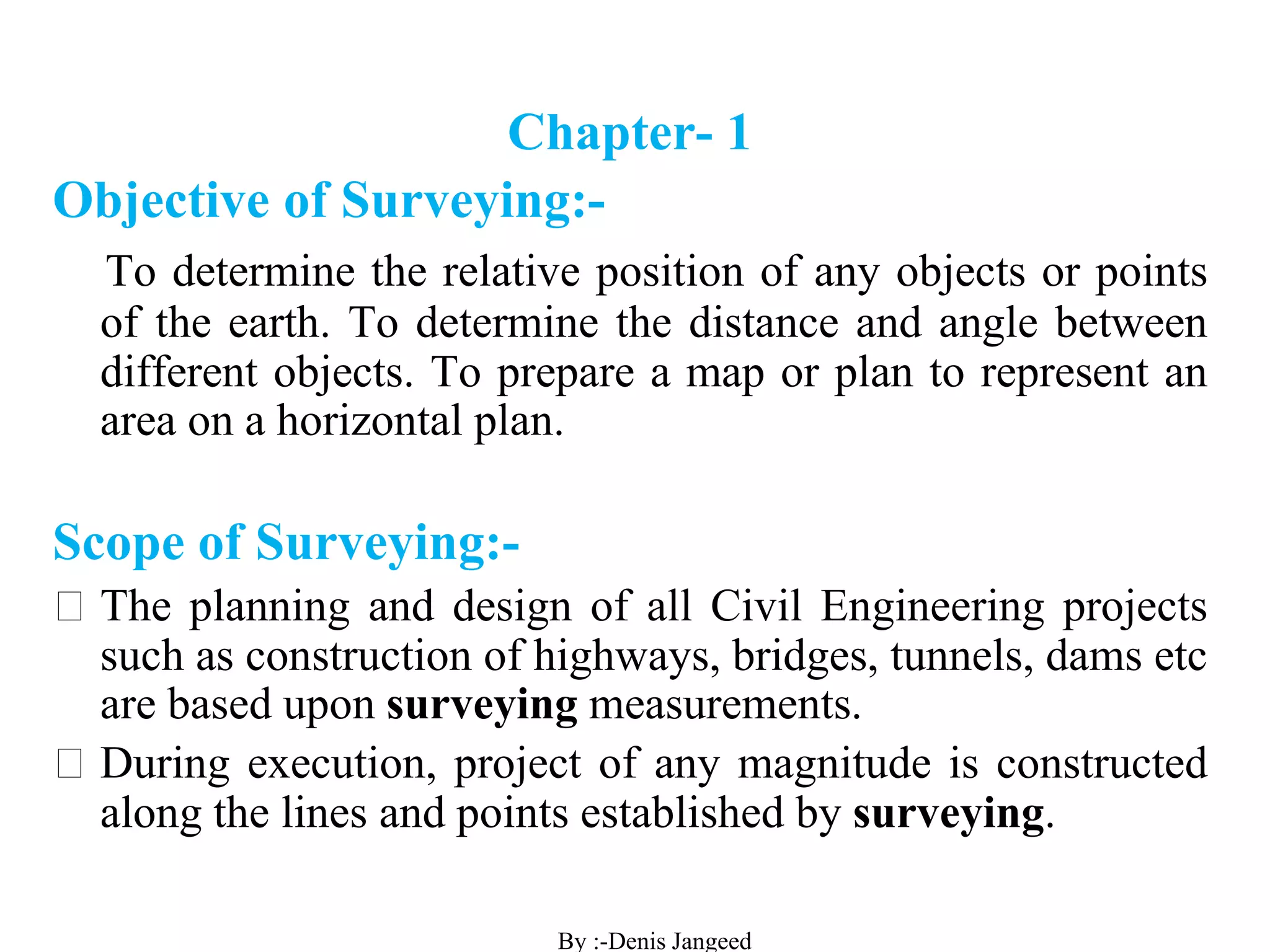
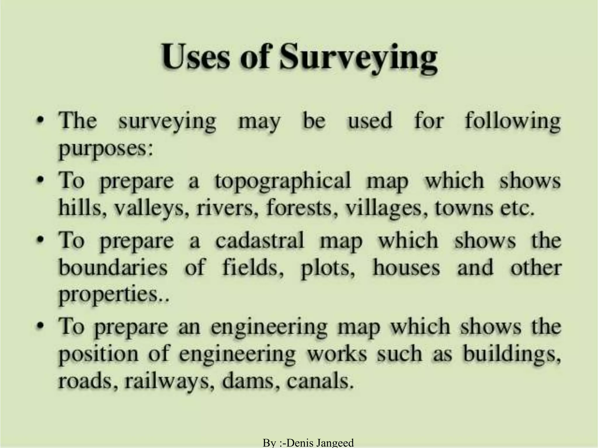
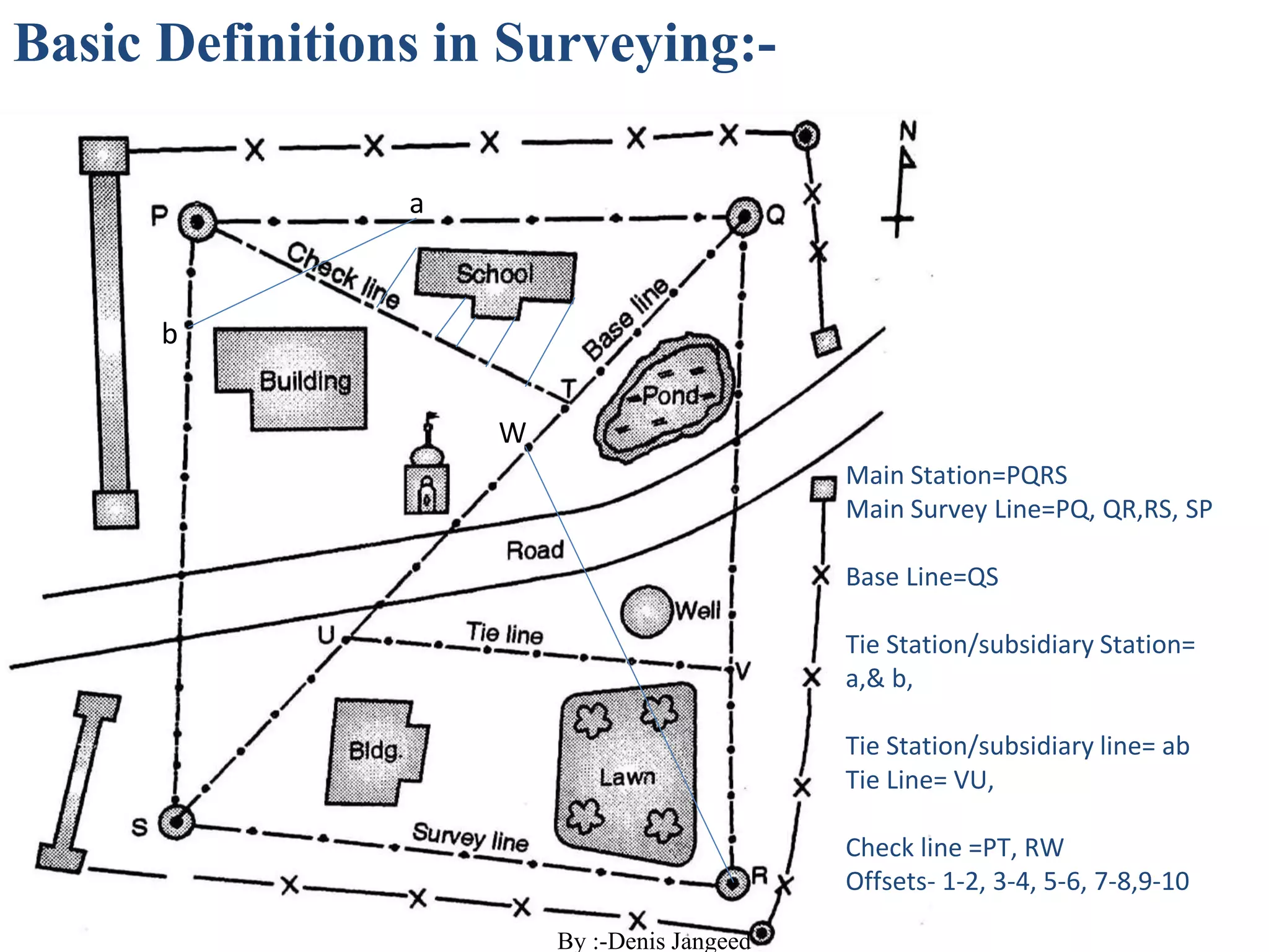
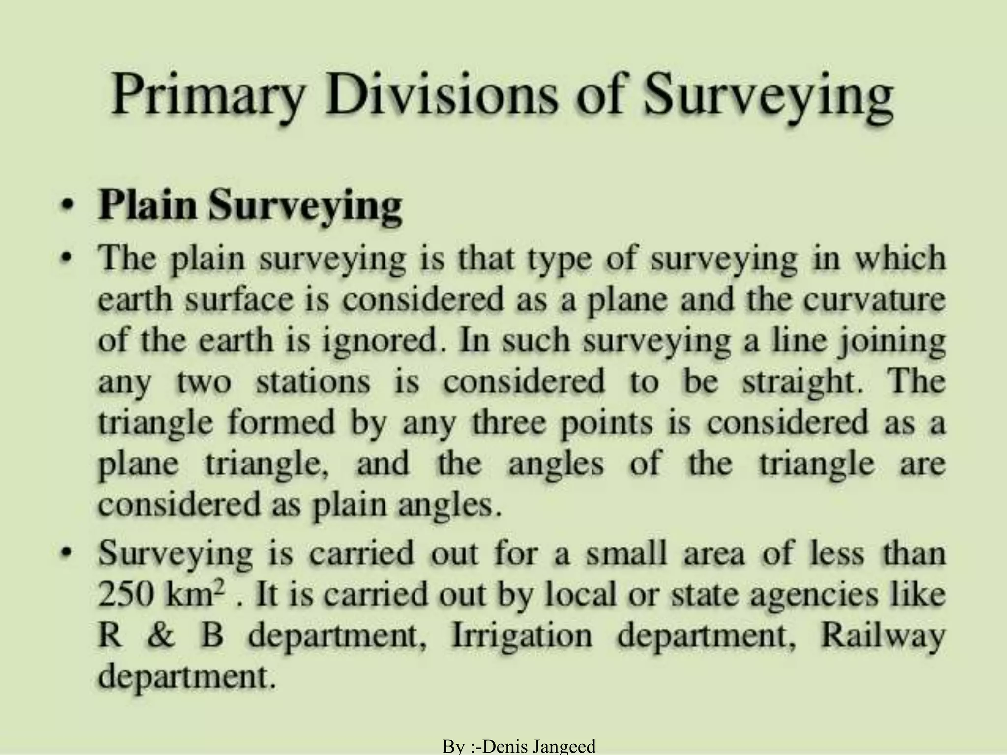
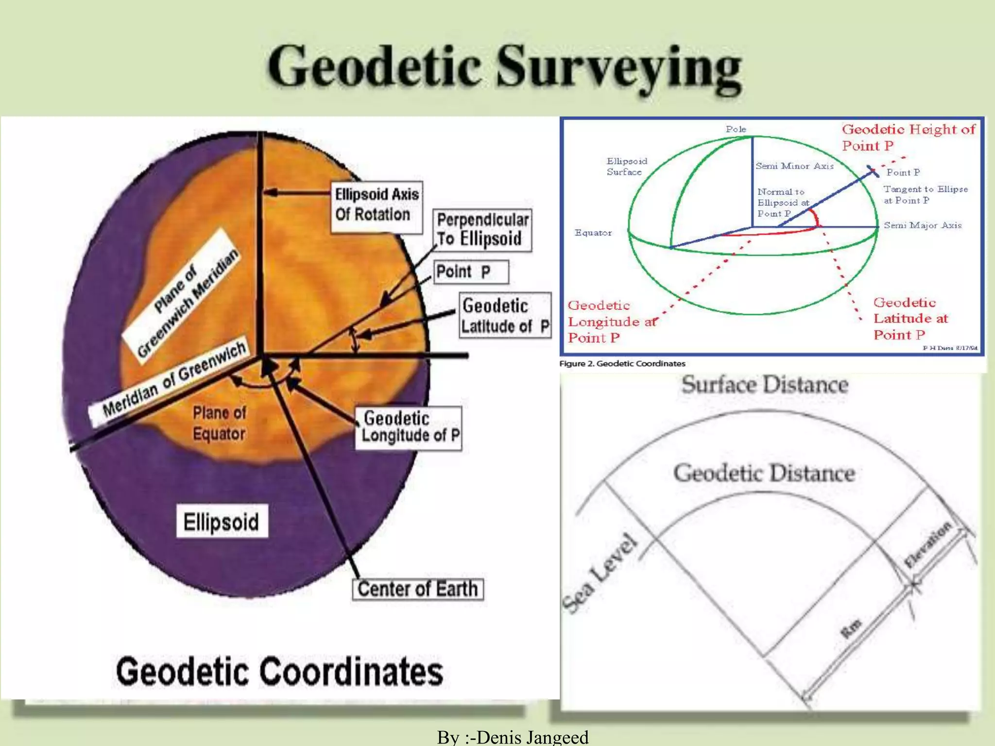
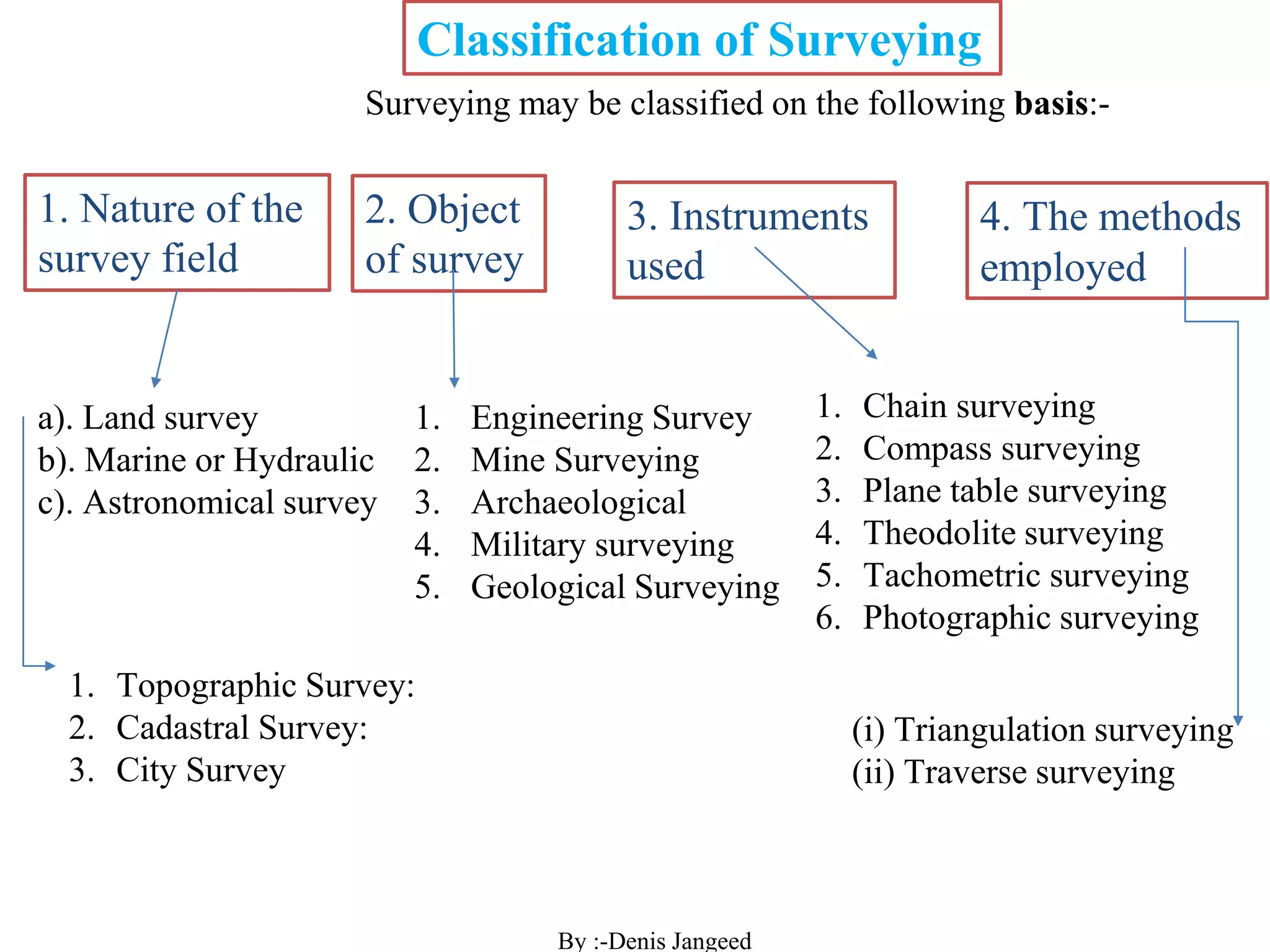
Surveying Subject Weightage for GATE & ESE.
Objective of Surveying
Scope of Surveying
Uses Of Surveying
LINEAR AND ANGULAR MEASUREMENTS in Surveying
Basic Definitions in Surveying
Divisions Of Surveying
Plumb Line
Plain & Geodetic Surveying
Fundamental Principles of Surveying
Plan, Maps & Scale & Their Types
RF
Classification of Surveying
Chain surveying
Methods of Linear measurements
Accessories used in Chain Surveying
Ranging Rod/Pole or Picket
Chaining
Types of Chains
types of tapes
Tape Correction
Ranging of Survey line
The process of ranging Direct Ranging & Indirect Ranging
Ranging by Line Ranger
Instrument used for measurement of Direction and Angle
Whole circle bearing (WCB)
Reduced Bearing (RB) Quadrant Bearing (QB)
Types of Meridian
Types of Bearing
Fore bearing and Back bearing
Compass Surveying
Traversing
Types of traverse surveying
Principle of Compass Surveying
Methods of Traversing
Traversing by Included Angle
Types of Compass
1.PrismaticCompass
2.Surveyor’sCompass
Temporary Adjustments for Prismatic Compass
Theodolite
Uses of Theodolite
Classification of Theodolite
Temporary adjustment of theodolite
MEASUREMENT OF HORIZONTAL ANGLES:-
a)Ordinary Method.
b)Repetition Method.
c)Reiteration Method.
Metric Chain : It Consists of galvanized mild steel wire of 4mm diameter known as link.
It is available in 20m, 30m, 50m length which consists of 100 links.
Gunter’s Chain : A 66 feet long chain consists of 100 links, each of 0.66 feet, it is known as Gunter’s chain.
This chain is suitable for taking length in miles.
Engineer’s Chain : A 100 feet long chain consisting of 100 links each of 1 feet is known as engineer’s chain.
This chain is used to measure length in feet and area in sq.yard.
Revenue Chain : it is 33 feet long chain consisting of 16 links.
This chain is used for distance measurements in feet & inches for smaller areas.
Definition of Surveying
Objects of Surveying
Uses of Surveying
Primary Divisions of Surveying
Principles of Surveying
List of Classification of Surveying
Definitions : Plan and Map, scales :Plain Scale and Diagonal Scale,
Introduction to surveying, ranging and chainingShital Navghare
This presentation contains the complete introduction of surveying. It also includes all the instrucments used in linear measurement and the terms related to Ranging and Chaining
This ppt presentation covers compass surveying, which explains principal of compass surveying, Types of compass, Difference between compass, Bearing, Definitions related to compass surveying etc.
Chain survey is the simplest method of surveying. ... The necessary requirements for field work are chain, tape, ranging rod, arrows and sometime cross staff. It is a system of surveying in which sides of various triangles are measured directly in the field and NO angular measurements are taken.
Content- Introduction to surveying and leveling
Object and Uses of Surveying, Fundamental Principles of Surveying, Introduction to conventional methods and equipment used for surveying and Leveling
Introduction to modern equipment’s used in surveying- EDM, Total Station, GIS,GPS, Remote sensing, planimeter.
Introduction to Topo sheets and use of maps.
Compass surveying is a type of surveying in which the directions of surveying lines are determined with a magnetic compass, and the length of the surveying lines are measured with a tape or chain or laser range finder. The compass is generally used to run a traverse line.
Input of Surveying in Civil Engineering.
Subject Name: CE-IS&GI
(Civil Engineering-Introduction Societal and Global Impact.
Surveying: The Planning And Design of all Civil Engineering Projects Such as construction of Highways , Bridges , Tunnels , Dams etc are based upon surveying measurements. Thus , surveying is a basic requirement for all Civil Engineering Projects.
Types of Surveying:
(i) Plane Surveying
(ii) Geodetic or Trigonometrical Surveying
Surveying Levelling & Contouring Unit 2 Notes updating.pptx (1).pdfDenish Jangid
Levelling
Datum
Reduced Level
Absolute Level
MSL
Back sight
Fore sight
Intermediate sight
Types of BenchMark
Height of instrument
Rise & Fall Method
Temporary benchmark
Great Trigonometric Survey BM
Line of Collimation
Barometric levelling
Trigonometric Leveling
Fly leveling
Profile leveling
Dumpy Level
Y level or Wye-level
Tilting Level
Reversible Level
Auto Level
Automatic Level
Levelling Staff
Self reading staff
Target staff
Contour
Characteristic of Contours
Uses of contours maps
Contour Interval and Horizontal Equivalent
Errors in leveling
Earth curvature
Refraction
Collimation errors
Numerical on HI, Rise & Fall Method
Solid waste management & Types of Basic civil Engineering notes by DJ Sir.pptxDenish Jangid
Solid waste management & Types of Basic civil Engineering notes by DJ Sir
Types of SWM
Liquid wastes
Gaseous wastes
Solid wastes.
CLASSIFICATION OF SOLID WASTE:
Based on their sources of origin
Based on physical nature
SYSTEMS FOR SOLID WASTE MANAGEMENT:
METHODS FOR DISPOSAL OF THE SOLID WASTE:
OPEN DUMPS:
LANDFILLS:
Sanitary landfills
COMPOSTING
Different stages of composting
VERMICOMPOSTING:
Vermicomposting process:
Encapsulation:
Incineration
MANAGEMENT OF SOLID WASTE:
Refuse
Reuse
Recycle
Reduce
FACTORS AFFECTING SOLID WASTE MANAGEMENT:
Basic Civil Engineering Notes of Chapter-6, Topic- Ecosystem, Biodiversity Green house effect & Hydrological cycle
Types of Ecosystem
(1) Natural Ecosystem
(2) Artificial Ecosystem
component of ecosystem
Biotic Components
Abiotic Components
Producers
Consumers
Decomposers
Functions of Ecosystem
Types of Biodiversity
Genetic Biodiversity
Species Biodiversity
Ecological Biodiversity
Importance of Biodiversity
Hydrological Cycle
Green House Effect
DEFINITION OF POLLUTION
Environmental pollution
Pollutants
Types of Pollution
Air Water Noise Land Pollution
NAAQS AQI Level
Central Pollution Control Boar
Environment Act, 1986
Air Quality Index (AQI) Level
Causes of Air Pollution
Fossil Fuels
Effects of Air Pollution
Air Pollution Control
Water Pollution & Types
Causes of Water Pollution
Standard Parameters drinking
Effects of Water Pollution
How to Avoid Water Pollution
Causes of Noise Pollution
Rainwater Harvesting
Effects of Noise Pollution
Prevention of Noise Pollution
Definition of Land Pollution
Causes of Land Pollution
Prevention of Land Pollution
Why is Rainwater Harvesting
Objectives of Rainwater Harvesting
Methods of Rainwater Harvesting
Surface runoff harvesting
Roof top rainwater harvesting
Basic Civil Engineering notes on Transportation Engineering, Modes of Transpo...Denish Jangid
Transport (British English) or Transportation (American English)
ransportation has developed along three basic Mode (Media):-
1. Land Transportation (way)–
(a) Road Transportation (b) Rail Transportation
2. Water Transportation
3. Air Transportation
Tramway
Inland water transport
Ocean transport
These may be classified as under:
(a). Liners
(b). Tramps
Liners Vs Tramps
Figure- Layout airport runway design
TRAFFIC SIGNS
Types of Traffic Signs:
1. Mandatory/Regulatory Signs
2. Cautionary/Warning Signs
3. Informatory/Guide Signs
STOP & Give way sign properties as per IS Code IRC 067: Code of Practice for Road Signs (Third Revision)
Causes of road accidents
ROAD SAFETY MEASURES
(1.) Engineering
(2.) Enforcement
(3.) Education
Basic Civil Engineering first year Notes- Chapter 4 Building.pptxDenish Jangid
Basic Civil Engineering notes
first year Notes
Building notes
Selection of site for Building
Layout of a Building
What is Burjis, Mutam
Building Bye laws
Basic Concept of sunlight
ventilation in building
National Building Code of India
Set back or building line
Types of Buildings
Floor Space Index (F.S.I)
Institutional Vs Educational
Building Components & function
Sills, Lintels, Cantilever
Doors, Windows and Ventilators
Types of Foundation AND THEIR USES
Plinth Area
Shallow and Deep Foundation
Super Built-up & carpet area
Floor Area Ratio (F.A.R)
RCC Reinforced Cement Concrete
RCC VS PCC
surveying_module-3-trigonometric-leveling by Denis Jangeed.pdfDenish Jangid
surveying_module-3-Trigonometric leveling by Denis Jangeed
Methods of Observation
Method of determining the elevation of
To obtain R.L of top of a ten storeyed building
following observation were taken.
Indirect levelling on a rough
terrain
a point by theodolite
• There are main three cases to determine the
R.L of any point.
• Case : 1 :- Base of Object accessible.
• Case : 2 :- Base of object inaccessible,
instrument station in the vertical plane as the
elevated object.
• Case : 3 :- Base of the object inaccessible ,
instrument stations not in the same vertical
plane as the elevated object.
There may be two case
A. Instrument axis at same level
B. Instrument axis at different level
Angle of elevation
Height of the instrument
Calculate reduce level of the top of the tower
from the following data.
Indirect levelling on a steep slope
Total station, parts of total station,
advantages and application.
Practical on Total station
To study the various electronic surveying instruments like EDM, Total Station etc. What is Total station?
Total Station with Tripod stand & Reflector prism
Basic components of Total station
It is also integrated with microprocessor, electronic data collector and storage system
Setting up the total station over a ground point
Area Calculation by Total Station
Volume Calculation by Total Station
RDM & REM by Total Station
AccuracyofaTotalStation
Remote elevation measurement
Applications of Total Station
Uses of Total Station
Total Station step by step
Field Practical of TS
EDM-Electronic Distance Measurement by Denis Jangeed.pptxDenish Jangid
EDM-Electronic Distance Measurement by Denis Jangeed
Origin of Electronic Distance Measurement
Principle of E.D.M. (Electronic Distance Measurements), Modulation,
Types of E.D.M., Distomat,
advantages and application.
electromagnetic waves
EDM Range 100 KM
EDM accuracy of 1 in 105
Electromagnetic Spectrum Range
microwaves, infrared waves and visible light waves
Measurement of distance with EDM and a Reflector
Classification of Electronic Distance Measurement Instrument
EDM instruments are classified based on the type of carrier wave as
Microwave instruments
Infrared wave instruments
Light wave instruments.
Parts of EDM instruments
Geodimeter
Tellurometer
Distomat
Errors in EDM
CURVE SURVEYING By Denis Jangeed
Type of Curves
Methods for Setting Out of Circular Curve
Broken-back Curve
Elements of Circular Curve
Elements of simple and compound curves, Types of curves, Elements of
circular, reverse, and transition curves. Method of setting out simple,
circular, transition and reverse curves, Types of vertical curves, length of
vertical curves, setting out vertical curves. Tangent corrections.Reverse Curve
Point of tangency Tangent distance Mid ordinate Length of Tangent Length of Chord
Linear Method
1.By Ordinates or Offsets from the Long Chord
2.Perpendicular Offset From Tangent
3.By Offset From Chord Produced (Deflection Distance)
4.Radial Offset From Tangent
5 Successive Bisection Of Chords
Angular Method
Tape & Theodolite/Rankine Method / Tangential / Deflection Angles
Two-theodolite Method
Tachometer Method
Degree of curvature
A Complete Guidance How to do Summer Industrial Training after 4th & 6th Seme...Denish Jangid
A Complete Guidance How to do Summer Industrial Training or internship after 4th & 6th Semester by Denis Jangeed.
company for summer training
application format training
Pre & Post evaluation form
feedback form for training
impact sheet for training
training format for college
Summer Industrial Training
Wind and Seismic Analysis WASA or Building Design Notes.pdfDenish Jangid
Wind and Seismic Analysis,
WASA notes,
Building Design Notes
framed tubes
Structural Systems:
Types of structures and Structure’s forms,
different type of design load,
load path diagram
Aspect ratio
overturning resistance
load combination
Symmetry and Asymmetry in building forms, Vertical and lateral load resting elements,
shear walls, framed tubes and various multi-storey configurations.
Evaluation of structural system,
strength and stiffness of a building,
seismic force,
lateral load resisting elements
building configuration and seismic design,
building design uplift racking overturning,
regular & irregular shape of building,
tube structured,
outrigger structure,
Wind and Seismic Analysis notes,
WRED Water Resources Engineering Design lab Record work by Mr.Denish JangidDenish Jangid
WRED Water Resources Engineering Design lab Record work by Mr.Denish Jangid
Index
1) A Canal was designed to supply the irrigation need of 1200 hectare of land growing rice of 140 days. Base period having a delta of 134 cm. If this canal water is used to irrigate wheat of base period 120days having a delta of 52cm. Calculate area of land that can be irrigated?
2) Design an irrigation channel using Kennedy’s theory to carry a discharge of 15 cumecs and take N=0.0225, m=1, S= 1in 5000
3) Design an irrigation channel using Lacey’s theory for a discharge of 20 cumecs and silt factor=1.0
4) Design an irrigation channel in a non erodible material to carry a discharge of 15 cumecs when max. Permissible velocity is 0.8m/sec. Assume bed slope 1 in 4000 side slope 1:1 & mannings N=0.025
5). Design a suitable cross-drainage work, given the following data at the crossing of a canal and drainage.
Canal: Drainage:
Full supply discharge = 32 cumecs High flood discharge = 300 cumecs
Full supply level = R.L. 213.5 High flood level = 210.0 m
Canal bed level = R.L. 212.0 High flood depth = 2.5 m
Canal bed width = 20 m General ground level = 212.5 m.
Trapezoidal canal section with 1.5 H: 1 V slopes.
Canal water depth = 1.5 m
6) Lab Problem Check the stability of Gravity dam?
7) One hour triangular unit hydrograph of a watershed has the peak discharge of 60 M3/Sec. at 10 hours & time base is 30 hours. The Ø- index is 0.4cm/hr. & base flow is 15 M3/Sec. Then Calculate
(i) Catchment area of watershed?
(ii) If there is rain fall of 5.4cm in hour then what are the ordinate of flood hydrograph at 15th hour?
WRE water resources engineering lab work by Mr. Denish JangidDenish Jangid
WRE water resources engineering lab work for civil engineering.
Index
Design a Sarda type fall for following data:
(i) Full supply discharge Us/Ds = 45 Cumec
(ii) Full supply Level Us/Ds = 118.30m/116.80m
(iii) Full supply depth Us/Ds = 1.8m/1.8m
(iv) Bed width Us/Ds = 28m/28m
(v) Bed level Us/Ds = 116.5m/115m
Drop 1.5m & Taking Bligh’s coefficient of creep =8
Calculate uplift pressure
Check the stability of gravity dam
A masonry dam 6 meter high
All FLUID MECHANICS (FM) Notes by Mr. Denish JangidDenish Jangid
All FLUID MECHANICS (FM) Notes by Mr. Denish Jangid
Fluids Definition, Type of fluids, Ideal fluids, real fluids, Newtonian and
non-Newtonian fluids.Properties of Fluids: Units of measurement, Mass density, Specific
weight, Specific volume, Specific Gravity, Viscosity, Surface tension and
Capillarity, Compressibility and Elasticity.Principles of Fluid Statics: Basic equations, Pascal Law, Type of
pressure:-atmospheric pressure, Gauge pressure, vacuum pressure,
absolute pressure, manometers, Bourdon pressure gauge.Buoyancy; Forces acting on immersed plane surface. Centre of pressure,
forces on curved surfaces. Conditions of equilibrium for floating bodies,
meta-centre and analytical determination of meta centric height.Kinematics of Flow: Visualisation of flow, Types of flow: Steady and
unsteady, uniform and non-uniform, rotational and irrotaional flow,
Laminar and turbulent flow, streamline, path line, streak line, principle of
conservation of mass, equation of continuity, acceleration of fluid
particles local and convective, velocity, acceleration, velocity potential and
stream function, elementary treatment of flow net, vorticity, circulation,
free and forced vortex. Fluid mass subject to horizontal and vertical
acceleration and uniform rotation.Fluid Dynamics: Control volume approach, Euler’s equation, Bernoulli’s
equation and its applications, venture-meter, orificemeter, orifices &
mouthpieces, time of emptying of tanks by orifices, momentum and
angular momentum equations and their applications, pressure on flat
plates and nozzles.Laminar Flow through Pipes: Laminar flow through pipes, Relation
between shear & pressure gradient. Flow between plates & pipes. Hagen-
Poiseuille equation, Equations for velocity distribution, pressure
difference velocity distribution over a flat plate and in a pipe section,
Darcy-Weisbach equation, friction factor , minor losses, pipe networks
Complete all notes WATER RESOURCE ENGINEERING (WRE)Denish Jangid
Introduction of WATER RESOURCE ENGINEERING: Objective, scope and outcome of the course.
Definitions, functions and advantages of irrigation,
present status of irrigation in India, classification for agriculture, soil moisture and crop water relations, Irrigation water quality. Consumptive use of water, principal Indian crop seasons and water requirements.
Canal Irrigation Types of canals, design of channels, regime and semi theoretical approaches (Kennedy’s Theory, Lacey’s Theory) Diversion Head works: Design for surface and subsurface flows, Bligh’s and Khosla’s methods.
Embankment Dams: Suitable sites, causes of failures, stability and seepage analysis, flow net, principles of design of earth dams. Gravity Dams: Force acting on a gravity dam, stability requirements..
Well Irrigation: Open wells and tube wells, types of tube wells, duty of tube well water. Cross-Drainage Structure: Necessity of Crossdrainage structures, their types and selection, comparative merits and demerits.
Hydrology: Definition, Hydrologic cycle, measurement of rainfall, Flood hydrograph, Rainfall analysis, Infiltration, Run off, Unit hydrograph and its determination. Irrigation Water Power and
Canal its types with design of channels by Denish Jangid sir.
covered kennedy lacey theory IS code method with comparison drawbacks. design of canal types of canal trapezoidal shape. Water Resource Engineering By KR Arora
Introduction of WATER RESOURCE ENGINEERING Unit 1 Definitions functions and a...Denish Jangid
Introduction of WATER RESOURCE ENGINEERING Definitions Unit 1, functions and advantages of irrigation, Types of Irrigation system, Field Capacity,Relationship between Duty Delta Base Period, classification of crops, classification of soil water agriculture, soil moisture, Irrigation water quality. Gross Command Area Consumptive use of water, principal Indian crop seasons and water requirements.Irrigation efficiency Scope of irrigation engineering
Spillways, Spillway capacity, flood routing through spillways, different type...Denish Jangid
Spillways: Spillway capacity, flood routing through spillways, different types & FUNCTION
of spillways and gate,Component parts of Spillways, energy dissipation below spillways Approach channel Control structure Discharge carrier Discharge channel Energy dissipators Overfall spillway spillway Saddle spillway Shaft spillway Side channel spillway Emergency spillway siphon spillway
water distribution system & warabandi by Denish Jangid unit 2 Water Resources...Denish Jangid
water distribution system & warabandi by Denish Jangid unit 2 Water Resources Engineering Rotational system method objectives of warabandi types of warabandi with flow chart figure jamabandi patwari girdawari halqa khasrah shudkar
Water Resources Engineering types of wells with figures Denish Jangid Open we...Denish Jangid
Water Resources Engineering types of wells with figuresOpen wells (Dug wells) Tube wells Wells and Tube Wells Irrigation in India Merit & Wells with Impervious lining CLASSIFICATION OF OPEN WELL BASED ON TYPE
OF Lining
Well with pervious lining : These type of wells are suitable in coarse formations these are constructed by masonry of dry bricks or stones without any binding materials. So the water supply enters from the wall of well therefore the flow is radial. Such wells are provided with bottom plug so the flow is not combination of radial and spherical.well with pervious lining CLASSIFICATION OF TUBE WELL BASED ON SUPPLY SYSTEM Strainer type tube well Cavity tube well
Slotted Type Tube well
CFD Simulation of By-pass Flow in a HRSG module by R&R Consult.pptxR&R Consult
CFD analysis is incredibly effective at solving mysteries and improving the performance of complex systems!
Here's a great example: At a large natural gas-fired power plant, where they use waste heat to generate steam and energy, they were puzzled that their boiler wasn't producing as much steam as expected.
R&R and Tetra Engineering Group Inc. were asked to solve the issue with reduced steam production.
An inspection had shown that a significant amount of hot flue gas was bypassing the boiler tubes, where the heat was supposed to be transferred.
R&R Consult conducted a CFD analysis, which revealed that 6.3% of the flue gas was bypassing the boiler tubes without transferring heat. The analysis also showed that the flue gas was instead being directed along the sides of the boiler and between the modules that were supposed to capture the heat. This was the cause of the reduced performance.
Based on our results, Tetra Engineering installed covering plates to reduce the bypass flow. This improved the boiler's performance and increased electricity production.
It is always satisfying when we can help solve complex challenges like this. Do your systems also need a check-up or optimization? Give us a call!
Work done in cooperation with James Malloy and David Moelling from Tetra Engineering.
More examples of our work https://www.r-r-consult.dk/en/cases-en/
NO1 Uk best vashikaran specialist in delhi vashikaran baba near me online vas...Amil Baba Dawood bangali
Contact with Dawood Bhai Just call on +92322-6382012 and we'll help you. We'll solve all your problems within 12 to 24 hours and with 101% guarantee and with astrology systematic. If you want to take any personal or professional advice then also you can call us on +92322-6382012 , ONLINE LOVE PROBLEM & Other all types of Daily Life Problem's.Then CALL or WHATSAPP us on +92322-6382012 and Get all these problems solutions here by Amil Baba DAWOOD BANGALI
#vashikaranspecialist #astrologer #palmistry #amliyaat #taweez #manpasandshadi #horoscope #spiritual #lovelife #lovespell #marriagespell#aamilbabainpakistan #amilbabainkarachi #powerfullblackmagicspell #kalajadumantarspecialist #realamilbaba #AmilbabainPakistan #astrologerincanada #astrologerindubai #lovespellsmaster #kalajaduspecialist #lovespellsthatwork #aamilbabainlahore#blackmagicformarriage #aamilbaba #kalajadu #kalailam #taweez #wazifaexpert #jadumantar #vashikaranspecialist #astrologer #palmistry #amliyaat #taweez #manpasandshadi #horoscope #spiritual #lovelife #lovespell #marriagespell#aamilbabainpakistan #amilbabainkarachi #powerfullblackmagicspell #kalajadumantarspecialist #realamilbaba #AmilbabainPakistan #astrologerincanada #astrologerindubai #lovespellsmaster #kalajaduspecialist #lovespellsthatwork #aamilbabainlahore #blackmagicforlove #blackmagicformarriage #aamilbaba #kalajadu #kalailam #taweez #wazifaexpert #jadumantar #vashikaranspecialist #astrologer #palmistry #amliyaat #taweez #manpasandshadi #horoscope #spiritual #lovelife #lovespell #marriagespell#aamilbabainpakistan #amilbabainkarachi #powerfullblackmagicspell #kalajadumantarspecialist #realamilbaba #AmilbabainPakistan #astrologerincanada #astrologerindubai #lovespellsmaster #kalajaduspecialist #lovespellsthatwork #aamilbabainlahore #Amilbabainuk #amilbabainspain #amilbabaindubai #Amilbabainnorway #amilbabainkrachi #amilbabainlahore #amilbabaingujranwalan #amilbabainislamabad
Cosmetic shop management system project report.pdfKamal Acharya
Buying new cosmetic products is difficult. It can even be scary for those who have sensitive skin and are prone to skin trouble. The information needed to alleviate this problem is on the back of each product, but it's thought to interpret those ingredient lists unless you have a background in chemistry.
Instead of buying and hoping for the best, we can use data science to help us predict which products may be good fits for us. It includes various function programs to do the above mentioned tasks.
Data file handling has been effectively used in the program.
The automated cosmetic shop management system should deal with the automation of general workflow and administration process of the shop. The main processes of the system focus on customer's request where the system is able to search the most appropriate products and deliver it to the customers. It should help the employees to quickly identify the list of cosmetic product that have reached the minimum quantity and also keep a track of expired date for each cosmetic product. It should help the employees to find the rack number in which the product is placed.It is also Faster and more efficient way.
About
Indigenized remote control interface card suitable for MAFI system CCR equipment. Compatible for IDM8000 CCR. Backplane mounted serial and TCP/Ethernet communication module for CCR remote access. IDM 8000 CCR remote control on serial and TCP protocol.
• Remote control: Parallel or serial interface.
• Compatible with MAFI CCR system.
• Compatible with IDM8000 CCR.
• Compatible with Backplane mount serial communication.
• Compatible with commercial and Defence aviation CCR system.
• Remote control system for accessing CCR and allied system over serial or TCP.
• Indigenized local Support/presence in India.
• Easy in configuration using DIP switches.
Technical Specifications
Indigenized remote control interface card suitable for MAFI system CCR equipment. Compatible for IDM8000 CCR. Backplane mounted serial and TCP/Ethernet communication module for CCR remote access. IDM 8000 CCR remote control on serial and TCP protocol.
Key Features
Indigenized remote control interface card suitable for MAFI system CCR equipment. Compatible for IDM8000 CCR. Backplane mounted serial and TCP/Ethernet communication module for CCR remote access. IDM 8000 CCR remote control on serial and TCP protocol.
• Remote control: Parallel or serial interface
• Compatible with MAFI CCR system
• Copatiable with IDM8000 CCR
• Compatible with Backplane mount serial communication.
• Compatible with commercial and Defence aviation CCR system.
• Remote control system for accessing CCR and allied system over serial or TCP.
• Indigenized local Support/presence in India.
Application
• Remote control: Parallel or serial interface.
• Compatible with MAFI CCR system.
• Compatible with IDM8000 CCR.
• Compatible with Backplane mount serial communication.
• Compatible with commercial and Defence aviation CCR system.
• Remote control system for accessing CCR and allied system over serial or TCP.
• Indigenized local Support/presence in India.
• Easy in configuration using DIP switches.
Hybrid optimization of pumped hydro system and solar- Engr. Abdul-Azeez.pdffxintegritypublishin
Advancements in technology unveil a myriad of electrical and electronic breakthroughs geared towards efficiently harnessing limited resources to meet human energy demands. The optimization of hybrid solar PV panels and pumped hydro energy supply systems plays a pivotal role in utilizing natural resources effectively. This initiative not only benefits humanity but also fosters environmental sustainability. The study investigated the design optimization of these hybrid systems, focusing on understanding solar radiation patterns, identifying geographical influences on solar radiation, formulating a mathematical model for system optimization, and determining the optimal configuration of PV panels and pumped hydro storage. Through a comparative analysis approach and eight weeks of data collection, the study addressed key research questions related to solar radiation patterns and optimal system design. The findings highlighted regions with heightened solar radiation levels, showcasing substantial potential for power generation and emphasizing the system's efficiency. Optimizing system design significantly boosted power generation, promoted renewable energy utilization, and enhanced energy storage capacity. The study underscored the benefits of optimizing hybrid solar PV panels and pumped hydro energy supply systems for sustainable energy usage. Optimizing the design of solar PV panels and pumped hydro energy supply systems as examined across diverse climatic conditions in a developing country, not only enhances power generation but also improves the integration of renewable energy sources and boosts energy storage capacities, particularly beneficial for less economically prosperous regions. Additionally, the study provides valuable insights for advancing energy research in economically viable areas. Recommendations included conducting site-specific assessments, utilizing advanced modeling tools, implementing regular maintenance protocols, and enhancing communication among system components.
Overview of the fundamental roles in Hydropower generation and the components involved in wider Electrical Engineering.
This paper presents the design and construction of hydroelectric dams from the hydrologist’s survey of the valley before construction, all aspects and involved disciplines, fluid dynamics, structural engineering, generation and mains frequency regulation to the very transmission of power through the network in the United Kingdom.
Author: Robbie Edward Sayers
Collaborators and co editors: Charlie Sims and Connor Healey.
(C) 2024 Robbie E. Sayers
1. Department of Civil Engineering
Subject- Surveying (3CE4-05)
Semester/ Year – 3/ 2
By
Denis Jangeed
2. Subject Weightage (as per previous patterns)
Exam Marks Weightage
GATE 4-6 Marks out of 100
State JE/Aen 10% of total Weightage
SSC JE 10% of total Weightage
ESE/IES (Objective) 18-22 marks out of 300
ESE/IES (Conventional) 60-75 marks out of 600
Books
1 Surveying volume-I & II by Dr. B.C. Punmia
2 Surveying volume-I & II by S.K. Duggal
By :-Denis Jangeed
3. Chapter- 1
Objective of Surveying:-
To determine the relative position of any objects or points
of the earth. To determine the distance and angle between
different objects. To prepare a map or plan to represent an
area on a horizontal plan.
Scope of Surveying:-
⮚ The planning and design of all Civil Engineering projects
such as construction of highways, bridges, tunnels, dams etc
are based upon surveying measurements.
⮚ During execution, project of any magnitude is constructed
along the lines and points established by surveying.
By :-Denis Jangeed
5. Outcomes:-
⮚ Students understand the basics of linear and angular
measurement.
⮚ To make students understand the measurement of level
and contour maps.
⮚ To introduce different Types of curves, setting out of
curves.
⮚ To brief students to different systems of tachometric
measurements.
⮚ To Setting out works & modern field survey systems.
By :-Denis Jangeed
6. Chapter-2
LINEAR AND ANGULAR MEASUREMENTS
Introduction of Surveying:-
❖As Per Dictionary Surveying = Collection of data
❖Surveying is the art/process of determining the
relative positions of any points on, above or
beneath the surface of the earth by performing
linear (Distance) and angular measurements.
❖And preparing a Plan & Map to any suitable scale.
❖Both Plan & Map are the graphical representation of the
features on a horizontal plane.
By :-Denis Jangeed
7. Basic Definitions in Surveying:-
Main Station=PQRS
Main Survey Line=PQ, QR,RS, SP
Base Line=QS
Tie Station/subsidiary Station=
a,& b,
Tie Station/subsidiary line= ab
Tie Line= VU,
Check line =PT, RW
Offsets- 1-2, 3-4, 5-6, 7-8,9-10
a
b
W
By :-Denis Jangeed
11. Plumb Line
Plumb
bob
Plumb Line
Self Weight W
Working on gravity of earth
C
O
In Geodetic survey plumb lines
are concentric.
Means all lines meet at centre of the earth
By :-Denis Jangeed
49. Classification of Surveying
Surveying may be classified on the following basis:-
1. Nature of the
survey field
2. Object
of survey
3. Instruments
used
4. The methods
employed
a). Land survey
b). Marine or Hydraulic
c). Astronomical survey
1. Topographic Survey:
2. Cadastral Survey:
3. City Survey
1. Engineering Survey
2. Mine Surveying
3. Archaeological
4. Military surveying
5. Geological Surveying
1. Chain surveying
2. Compass surveying
3. Plane table surveying
4. Theodolite surveying
5. Tachometric surveying
6. Photographic surveying
(i) Triangulation surveying
(ii) Traverse surveying
By :-Denis Jangeed
51. a). Land Survey:- It involves measurement of various
objects on land.
This type of survey may be further classified as given
below:
1. Topographic Survey:
It is meant for plotting natural features like rivers,
lakes, forests and hills as well as man made features
like roads, railways, towns, villages and canals.
2. Cadastral Survey:
It is for marking the boundaries of municipalities,
villages, districts, states etc. The survey made to mark
properties of individuals also come under this category.
By :-Denis Jangeed
52. 3. City Survey:
The survey made in connection with the construction of streets,
water supply and sewage lines fall under this category.
b). Marine or Hydrographic Survey:-
Survey conducted to find depth of water at various points in bodies
of water like sea, river and lakes fall under this category. Finding
depth of water at specified points is known as sounding.
c).Astronomical Survey:-
Observations made to heavenly bodies like sun, stars etc., to locate
absolute positions of points on the earth.
By :-Denis Jangeed
54. 2. Classification based on object of survey:-
⮚ Engineering Survey
⮚ Mine Surveying
⮚ Archaeological surveying
⮚ Military surveying
⮚ Geological Surveying
⮚ Engineering surveys:-
The objective of this type of survey is to collect data
for designing civil engineering projects like roads,
railways, irrigation, water supply and sewage
disposals.
By :-Denis Jangeed
55. ⮚ Mines Surveying:-
This is used for exploring mineral wealth.
⮚ Archaeological Survey:-
This survey is for unearthing relics of antiquity.
⮚ Military Survey:-
This survey is meant for working out plans of strategic
importance.
⮚ Geological Survey:-
This survey is for finding different strata in the earth’s
crust.
65. 3. Based on Instruments used:-
⮚Chain surveying
⮚Compass surveying
⮚Plane table surveying
⮚Theodolite surveying
⮚Tachometric surveying
⮚Photographic surveying
⮚ Chain surveying:-
▪ The chain survey is the simplest method of surveying.
In the chain survey, only measurements are taken in
the field.
▪ Only linear measurements are made i.e. no angular
measurements are made.
▪ This is most suitably adapted to small plane areas with
very few details.
By :-Denis Jangeed
67. ⮚ Compass Surveying:-
Compass surveying is the branch of surveying in which
the position of an object is located using angular
measurements determined by a compass and linear
measurements using a chain or tape.
⮚ Plane Table Survey:-
• The plane table surveying is the fast method of
surveying. In this type of surveying plotting of the plan
and field observations can be done simultaneously.
• In case of plane table surveying Geometrical
conditions of site are manuscript in the map sheet
using plane table and alidade after that topographic
details are arranged on the map.
By :-Denis Jangeed
70. ⮚ Tacheometric Survey:-
▪ Tacheometry is a branch of angular surveying in which
the horizontal and vertical distances are obtained by
optical means as opposed to the ordinary process of
chain and tape.
▪ This is done with the help of two special type of
instruments- transit Theodolite and stadia rod.
⮚ Photographic surveying:-
▪ Photogrammetric surveyors specialize in the science of
obtaining reliable spatial information from
photographic images.
▪ Photogrammetrists analyze aerial and terrestrial
photographs to obtain information about physical
objects and the environment
By :-Denis Jangeed
71. 4. Classification based on methods used:-
Based on methods adopted, surveying can be categorized into:
(i) Triangulation surveying
(ii) Traverse surveying
(i) Triangulation:-
In this method control points are established through a
network of triangles.
(ii) Traversing:-
In this scheme of establishing control points consists of a
series of connected points established through linear and
angular measurements. If the last line meets the starting point
it is called as closed traverse. If it does not meet, it is known as
open traverse
By :-Denis Jangeed
72. ⮚Methods of Linear measurements:-
Various methods used for linear measurements may be
grouped as
(i) Approximate (Direct measurement)
(ii) Chaining
(iii) By optical means
(iv) Using electromagnetic distance measurement
instruments
(i) Approximates Methods of Linear (Direct) Measurements:-
These methods are used in reconnaissance survey. On
smooth roads they can give results within 1 per cent error.
These approximate measurements may be by
(a) Pacing
(b) Passometer
(c) Pedometer
(d) Odometer
(e) Speedometer
By :-Denis Jangeed
73. (a) Pacing:
▪ In this method surveyor walks along the line to be measured
and counts the number of steps.
▪ The distance measured = Number of steps × average length of
a step.
▪ Average length of a step can be found by walking along a
known length. A normal man takes a step of length 0.75 m to
0.8 m.
By :-Denis Jangeed
74. (b) Passometer:
▪ A Passometer is a watch-like instrument which is carried
vertically in the pocket of shirt or tied to a leg.
▪ It records number of steps taken. Thus the problem of counting
number of steps is eliminated in this approximate method of
linear measurement.
Passometer
By :-Denis Jangeed
75. (c) Pedometer:
▪ This instrument is similar to Passometer but it can record the
distance instead of number of steps.
▪ In this, zero setting and setting of step length is made before
walking.
Pedometer
By :-Denis Jangeed
76. (d) Odometer:
▪ This instrument is attached to the wheel of a cycle or other
vehicle.
▪ It records the number of revolutions made by the wheel.
Knowing the circumference of the wheel, the distance
travelled may be found.
By :-Denis Jangeed
77. (e) Speedometer:
▪ Its gives us Speed & Distance both & tip also.
▪ Odometer calibrated to give distance directly is called
speedometer.
▪ This is to be used for particular vehicle only.
By :-Denis Jangeed
78. Accessories used in Chain Surveying
Pegs
▪ Wooden pegs of 15cm length and 3 cm square in
section are used to establish the main station
points or the end points of a line on the ground.
▪ They are tapered one end and are driven into the
ground by using a wooden hammer.
▪ About 4 cm is left projecting above the ground.
By :-Denis Jangeed
79. Accessories used in Chain Surveying
Arrow- Chain Pins
▪ Chain pins or arrows are used with the chain
for marking each chain length on the ground.
▪ The arrow is driven into the ground at the
end of each chain length is measured.
▪ Chain pins the arrow should be made of
good quality hardened and tempered steel
wire of minimum tensile strength of 70
kg/mm
2.
▪ The overall length is 400 mm and
thickness is 4mm.
▪ The arrow has a circular eye at the one end
is pointed at the other end .
▪ Mostly used for intermediate station
By :-Denis Jangeed
80. Accessories used in Chain Surveying
Ranging Rod/Pole or Picket
By :-Denis Jangeed
81. Accessories used in Chain Surveying
Ranging Rod
▪ Ranging rod is used for ranging or aligning long lines on the
ground in field surveying.
▪ Ranging is a straight line means fixing a series of pegs or
other marks such that they all lie on a straight line.
▪ Ranging rods are used marking points on the ground so that the
positions of the points are distinctly visible from some distant way.
▪ The length of ranging rod may be 2 m and 3 m and its
diameter is 30 mm.
▪ Ranging rod made of steel tube or made of well seasoned,
straight grained timber of circular cross section.
By :-Denis Jangeed
82. Accessories used in Chain Surveying
Ranging Rod
▪ Ranging rods should be straight
and free from wraps.
▪ The deviation in straightness should
not exceed 5 mm in a 2 m length.
▪ The ranging rod is painted in red
and white in alternate band
lengths of 200 mm each.
▪ The bottom end of the rod is fitted
with a pointed, hollow, cast iron
shoe or steel shoe of 15 cm length.
By :-Denis Jangeed
83. Accessories used in Chain Surveying
Offset Rod
▪ It is a ranging rod with two short, narrow, vertical sighting
slots passing through the centre of the section.
▪ A hook is fitted of a groove is cut at the top to enable pulling
or pushing of the chain through obstruction like hedges.
▪ Offset rods are meant for setting outlines approximately
at right angles to the main line.
By :-Denis Jangeed
84. Accessories used in Chain Surveying
Cross Staff
▪ It is used to set out right angles in chain surveying
▪ It consists of four metal arms vertical slits mounted on
a pole.
▪ Two opposite slits are positioned along the length of a
line (Main Line)
▪ A line perpendicular to the main line is formed or
sighted through the other two slits
85. Accessories used in Chain Surveying
Plumb Bob
▪ It consists of a solid conical piece
and a string attached to it at its
centre.
▪ When in use, the solid piece is at
the bottom.
▪ It is used to test the verticality of the
ranging rods and to transfer the
points to the ground.
▪ Plumb bob is used while doing
chain surveying on sloping ground.
By :-Denis Jangeed
86. (ii) Chaining:-
▪ Chaining method determines the distance by means of a tape or
a chain. This is one of the accurate methods to determine the
linear measurements.
▪ The chain is used for ordinary precision.
▪ Tape is used to measure distance with high precision.
Chains:-
Depending upon the length of the chain, these are divided into
following types
▪ Metric chains
▪ Steel band or Band chain
▪ Gunter’s chain or surveyor’s chain
▪ Revenue chain
▪ Engineer’s chain
By :-Denis Jangeed
87. Metric chains:-
▪ Metric chains are the most commonly used chain in India.
▪ These types of chains comes in many lengths such as 5, 10, 20 and 30
meters. Most commonly used is 20m chain.
▪ Tallies are provided at every 1m of the chain for quick reading. Every
link of this type of chain is 0.2m. The total length of the chain is
marked on the brass handle at the ends.
▪ As per IS code:1492.1970 for Metric surveying chains
▪ https://law.resource.org/pub/in/bis/S01/is.1492.1970.pdf
By :-Denis Jangeed
88. Steel band or Band chain:-
▪ These types of chain consist of a long narrow strip of steel
of uniform width of 12 to 16 mm and thickness of 0.3 to
0.6 mm.
▪ This chain is divides by brass studs at every 20cm or
instead of brass studs, band chain may have graduated
engraving as centimetre.
▪ For easy use and workability band chains are wound on
steel crosses or metal reels from which they can be easily
unrolled.
By :-Denis Jangeed
89. Gunter’s chain or Surveyor’s chain:-
▪ Gunter chain comes in standard 66ft. These chain consists
of 100 links, each link being 0.66ft or 7.92inches. The
length 66ft is selected because it is convenient in land
measurements.
▪ 10 square Gunter’s chains = 1 Acre
▪ 10 Gunter chains = 1 Furlong
▪ 80 Gunter chains = 1 mile=1.6093 KM
By :-Denis Jangeed
90. Revenue Chain:-
▪ The standard size of this type of chain is 33ft. The number
of links are 16, each link being 2.0625 ft
▪ This chain is commonly used in cadastral survey.
By :-Denis Jangeed
91. Engineer’s chain:-
▪ This chain comes in 100 ft length.
▪ Its consist of 100 links each link being 1ft long.
▪ Tallies are provided at every 3m (For 30m Chain) of the chain for
quick reading.
▪ At every 10 links a brass ring or tags are provided for indication
of 10 links. Readings are taken in feet and decimal. Used for all
engineering works like- Roads,canals,
▪ Made of galvanised mild steel. Link dia- 4MM.
By :-Denis Jangeed
93. Tape:-
Tapes are used in surveying for measuring horizontal, vertical
distances. Tapes are issued in various lengths, widths and materials
graduated in a variety of ways.
Following types of tapes available in surveying for linear measurements
and they are as follows :-
▪ Linen/cloth Tape
▪ Metallic Tape
▪ Steel Tape
▪ Invar Tape
By :-Denis Jangeed
94. Linen/cloth Tape:-
▪ Linen tape, also known as cloth tape is a varnished strip made of
closely woven linen. The width of the strip is about 12 to 15 mm.
▪ It is available in different lengths such as 10m, 20m, 25m, and 30m.
▪ Linen tapes are light in weight and easy to handle as compare to
chain.
▪ These tapes are not suitable for accurate surveying measurements.
▪ These are generally used for measuring offsets and for ordinary
works.
By :-Denis Jangeed
95. Metallic Tape:-
▪ The metallic tape is an improved version of linen tape. Brass or copper made
wires are used as reinforcement for the linen material.
▪ It is more durable than normal linen tape. A brass ring is provided at the end
of the tape which is included in the length of the tape.
▪ These tapes are available in different lengths of 2m, 5m, 10m, 20m, 30m,
and 50m.
▪ These are used for survey works such as topographical survey works where
minor errors are not taken into consideration.
By :-Denis Jangeed
96. Steel Tape:-
▪ A steel tape is made of steel or stainless steel & its a very lightweight.
▪ Easy to handle.
▪ It consists of a steel strip of 6mm to 16mm wide.
▪ It is available in lengths of 1m, 2m, 5m, 8m, 10m, 20m, 30m and
50m. Meters, decimetres, and centimetres are graduated in the steel
strip.
By :-Denis Jangeed
97. Invar Tape:-
▪ Invar tapes are made of an alloy which consists of 36% of nickel and
64% of steel.
▪ Invar tape contains a 6mm wide strip and is available in different
lengths of 30m, 50m, 100m.
▪ The coefficient of thermal expansion of invar alloy is very low.
▪ It is not affected by changes in temperature. Hence, these tapes are
used for high precision works in surveying such as baseline
measurement, triangulation surveys, etc.
▪ Invar tapes are expensive than all the other types of tapes.
▪ These tapes should be handled with care otherwise bends or kinks
(knot) may be formed.
By :-Denis Jangeed
119. Chain or Tape Correction:-
The following corrections provided for chain or tape measurements
while conducting chain or tape surveying are:-
1. Correction for absolute length
2. Correction for pull or tension
3. Correction for temperature
4. Correction for Sag
5. Correction for Slope
6. Correction for Alignment
The correction is
▪ Positive (+ve) if the erroneous length is to be increased or Negative
▪ Negative (-ve) if the erroneous length must be decreased or Positive
By :-Denis Jangeed
120. 1. Correction for Absolute Length
▪ If Ca is the correction for absolute length or the actual
length, then it is given by:
Where, L = Measured length of the line; c = Correction per
tape length; l= designated length of the tape or the nominal
length.
▪ Different cases are:
1. Absolute length > Designated length means Measured
distance is short, hence the correction is additive.
2. Absolute length < Designated length means, Measured
distance is long, hence the correction is subtractive.
The sign of correction Ca is the same as that of ‘c’.
Ca = L*c/l
By :-Denis Jangeed
121. 2. Correction for Temperature
▪ The correction for temperature Ct is given by the formula:
Where
α = Coefficient of thermal expansion
Tm = the mean temperature in the field during
measurement
To = the temperature during the standardization of the tape
L = Measured length
There are two cases possible:-
1. Tm > To
Hence the correction is additive.
2. Tm<To
Hence the correction is subtractive.
Ct = α (Tm –To) L
By :-Denis Jangeed
122. 3. Correction for Pull or Tension
The correction for pull or tension is given by the formula:-
Where,
P = Pull applied during the measurement (N)
Po= Standard Pull (N)
L = measured length (m)
A =Area of cross-section in (cm2)
E = Young’s modulus in (N/cm2)
Two cases are possible:-
1. if P > Po, then correction is (+ve)
2. if P < Po, then correction is (-ve)
By :-Denis Jangeed
123. 4. Correction for Sag:-
▪ Stretching the tape between two supports make the tape to
form a horizontal catenary. Hence, the horizontal distance
becomes greater than the distance along the curve.
▪ Sag Correction = (Horizontal distance – length along the
horizontal catenary)
▪ Tape correction per length is given by,
Where,
Cs = Tape Correction per Tape length
l=Total length of the tape
W= total weight of the tape
n= number of equal spans
P= Pull applied
Cs = lW2 /24n2P2
By :-Denis Jangeed
124. 5. Correction for Slope or Vertical Alignment
The slope correction or correction due to vertical alignment is
given by the relation:
Or
Where,
h = The difference in elevation between the ends;
x = slope measured
The distance that is measured along the slope is always greater
than the horizontal distance. This makes the correction to be
subtractive.
Cv = 2L sin2(x/2) b
L
h
By :-Denis Jangeed
125. 6. Correction for Horizontal Alignment
▪ Stretching the tape out of line results in greater distance value. The
correction is therefore negative.
▪ AB is the measured length and AC is the correct alignment. Hence, the
correction is given by:
Ch = d2/2L
L
l
d
B1
A B
By :-Denis Jangeed
129. Ranging of Survey line:-
▪ While measuring the survey lines,
the chain or the tape has to be
stretched along the survey line along
that joins two terminal stations.
▪ When the line to be measured has a
smaller length compared to the chain,
then the measurement goes smooth.
If the length of the line is greater, the
survey lines have to be divided by
certain intermediate points, before
conducting the
chaining process. This process is
called ranging.
By :-Denis Jangeed
130. The process of ranging can be done by two methods:-
1. Direct Ranging
2. Indirect Ranging
1. Direct Ranging:-
▪ Direct ranging is the ranging conducted when the intermediate
points are intervisible.
▪ Direct ranging can be performed by eye or with the help of an
eye instrument.
By :-Denis Jangeed
131. Ranging by Eye:-
▪ let A and B are the two intervisible points at the ends of the
survey line.
▪ The surveyor stands with a ranging rod at the point A by
keeping the ranging rod at the point B. The ranging rod is held
at about half metre length. The assistant then takes the ranging
rod and establishes at a point in between AB, almost in line
with AB. This is fixed at a distance not greater than one chain
length from point A.
▪ The surveyor can give signals to the assistant to move traverse
till the rod is in line with A and B. In this way, other
intermediate points are determined.
By :-Denis Jangeed
132. Ranging by Line Ranger
▪ A line ranger that has either two plane mirror arrangement or two isosceles
prisms that are placed one over the other. The diagonals of the prism are
arranged and silvered such that they reflect incident rays.
▪ In order to handle the instrument in hand a handle with hook is provided.
The hook is to enable a plumb - bob to help transfer the point to the
ground. In order to range the point ‘P’, initially two rods are fixed at points
A and B. By eye judgment, the surveyor holds the ranging rod at P almost
in line with AB.
▪ The lower prism abc receives the rays coming from A which is then
reflected by the diagonal ac towards the observer. The upper prism dbc
receives the rays from B which is then reflected by the diagonal bd
towards the observer. Hence the observer can see the images of the
ranging rods A and B, which might not be in the same vertical line.
▪ The surveyor moves the instrument till the two images come in the same
vertical line .With the help of a plumb bob, the point P is then transferred
to the ground. This instrument can be used to locate the intermediate
points without going to the other end of the survey line. This method only
requires one person to hold the line ranger.
By :-Denis Jangeed
134. 2. Indirect Ranging
▪ Indirect ranging is employed when the two points are not intervisible
or the two points are at a long distance. This may be due to some
kind of intervention between the two points.
▪ In this case, the following procedure is followed:-
⮚ Two intermediate points are located M1 and N1 very near to
chain line by judgment such that from M1, both N1 and B
are visible & from N1 both M1 and A are visible.
⮚ At M1 and N1 two surveyors stay with ranging rods. The
person standing at M1 directs the person at N1 to move to a
new position N2 as shown in the figure. N2 must be inline
with M1B.
⮚ Next, a person at N2 directs the person at M1 to move to a
position M2 such that it is inline with N2A. Hence, the two
persons are in points are M2 and N2.
⮚ The process is repeated until the points M and N are in the
survey line AB. Finally, it reaches a situation where the
person standing at M finds the person standing at N in line
with NA and vice versa. Once M and N are fixed, other
points are fixed by direct ranging.
By :-Denis Jangeed
136. Instrument used for measurement of Direction and Angle:-
(a) Direction
1. Surveyor Compass
2. Prismatic Compass
(b) Angle
1. Sextant
2. Theodolite
Bearing and Angle:-
Bearing:-
• Bearing of a line is its direction relative to a given meridian. or
• The bearing of a line is the horizontal angle which it makes with a reference line
(meridian) depending upon the meridian, there are four types of bearings.
Angle:- It is difference in direction between to intersection lines.
Designation of bearing:-
The common system of notation of bearing
1. Whole circle bearing (WCB)
2. Reduced Bearing (RB) or Quadrantal Bearing (QB)
By :-Denis Jangeed
139. 1. Whole circle bearing (WCB):-
▪ Bearings measured from north in a clockwise direction is
termed as whole circle bearing.
▪ The value varies from 0 degrees to 360 degrees.
▪ Ex.- Prismatic compass
By :-Denis Jangeed
140. 2. Reduced Bearing (RB) or Quadrantal Bearing (QB)
▪ The bearings measured either from the north or from the
south towards east or west whichever is nearer is known as
reduced bearing.
▪ The values vary from 0 degrees to 90 degrees for a
particular quadrant.
▪ It is also known as Quadrantal bearing (QB).
▪ Ex.- Surveyor compass
By :-Denis Jangeed
141. Conversion of bearing from one system to other system:-
(a) W.C.B to Q.B (R.B)
Line W.C.B
(Degree)
R.B Quadrant
AB 0 & 90 R.B = W.C.B NE
AC 90 & 180 R.B = 180- W.C.B SE
AD 180 &
270
R.B = W.C.B – 180 SW
AF 270 &
360
R.B = 360- W.C.B NW
By :-Denis Jangeed
142. (b) Q.B (R.B) to W.C.B
Line R.B W.C.B W.C.B
Between
AB Nø1E W.C.B= R.B 0 & 90
AC Sø2E W.C.B= 180-
R.B
90 & 180
AD Sø3W W.C.B=
180+ R.B
180 & 270
AF Nø4W W.C.B= 360-
R.B
270 & 360
By :-Denis Jangeed
143. Bearing:- The bearing of a line is the horizontal angle which it makes
with a reference line (meridian) depending upon the meridian, there are
four types of bearings.
Meridian:-Meridians are imaginary lines of longitude on the earth
that extend from the North to South Pole. A principal meridian is
one which is used as a reference line to survey a large area. There are
four types of meridians.
By :-Denis Jangeed
Types of Meridian:- Types of Bearing:-
True Meridian (TM) True Bearing (TB)
Magnetic Meridian (MM) Magnetic Bearing (MB)
Grid Meridian (GM) Grid Bearing (GB)
Arbitrary Meridian (AM) Arbitrary Bearing (AB)
144. 1. True meridian:-
▪ True meridian through a point is the line in which a plane, thus
passes through the true north and south poles, intersects with the
surface of the earth. It thus passes through the true north and
south.
▪ The direction of the true meridian through a point can be
established by astronomical observations.
▪ It is also known as Azimuth
True Bearing:
▪ True bearing of a line is the horizontal angle which it makes with
the true meridian through one of the extremities of the line.
▪ The direction of the true meridian through a point remains fixed,
the true bearing of a line is a constant quantity.
By :-Denis Jangeed
145. 2. Magnetic Meridian:-
▪ The magnetic bearing through a point is the direction shown
by a freely floating and balanced magnetic needle free from
all other attractive forces.
▪ The direction of magnetic meridian can be established with
the help of a magnetic compass.
Magnetic bearing:-
▪ The magnetic bearing of a line is the horizontal angle which
it makes with the magnetic meridian passing through one of
the extremities of the line.
▪ A magnetic compass is used to measure it.
By :-Denis Jangeed
146. 3. Grid meridian
▪ For survey of a country, the true meridian passing
through the central place is sometimes taken as a
reference meridian for the whole country. Such a
reference meridian is known as grid meridian. The
meridians of all other places in that state are assumed to be
parallel to the grid meridian
Grid bearing:
▪ The grid bearing of a line is the horizontal angle which the
line makes with the grid meridian.
By :-Denis Jangeed
147. 4. Arbitrary meridian
▪ Arbitrary meridian is any convenient direction towards a
permanent and prominent mark or signals, such as a church
spire or top of a chimney.
▪ Such meridians are used to determine the relative positions
of lines in a small area
Arbitrary bearing:
▪ Arbitrary bearing of a line is the horizontal angle which it
makes with any arbitrary meridian passing through one of
the extremities.
▪ A theodolite or sextant is used to measure it.
By :-Denis Jangeed
148. Fore bearing and Back bearing:-
▪ Fore bearing
The bearing of a line measured in the forward direction of
the survey lines is called the 'fore bearing'(F.B.) of that line.
▪ Back bearing
The bearing of a line measured in direction backward to the
direction of the progress of survey is called the 'back
bearing'(B.B.) of the line.
▪ Relation between F.B. And B.B.
+ve if F.B < 180º
-ve if F.B > 180º
B.B = F.B ± 180
By :-Denis Jangeed
160. By :-Denis Jangeed
Compass Surveying: -
▪ Chain surveying can be used when the area to be surveyed is
comparatively small and is fairly flat.
▪ But when the area is large, undulated and crowded with many
details, triangulation (which is the principle of chain survey) is not
possible. In such an area, the method of traversing is adopted.
Traversing :-
▪ Traversing is that type of survey in which a number of
connected survey lines form the framework and the directions and
lengths of the survey lines are measured with the help of an angle
measuring instrument and tape or chain respectively. This process
is known as Compass Traversing.
161. Types of traverse surveying.
They are two types:-
1. Closed traverse:-
When the lines form a circuit which ends at the starting point, it is
known as a closed traverse. Like -Pond
2. Open traverse:-
When the lines form a circuit ends elsewhere except starting
point, it is said to be an open traverse. Like village street to
highway then international highway.
By :-Denis Jangeed
162. Principle of Compass Surveying
• The Principle of Compass Survey is Traversing; which involves
a series of connected lines the magnetic bearing of the lines are
measured by prismatic compass and the distance (lengths) of the
are measured by chain. Such survey does not require the
formulation of a network of triangle.
• Compass surveying is recommended when the area is large,
undulating and crowded with many details.
• Compass surveying is not recommended for areas where local
attraction is suspected due to the presence of magnetic
substances like steel structures, iron ore deposits, electric cables
conveying currents, and so on.
By :-Denis Jangeed
163. Methods of Traversing
There are several methods of traversing, depending on the
instruments used in determining the relative directions of the
traverse lines.
The following are the principal methods:-
1. Chain traversing
2. Chain and compass traversing
3. Transit type traversing
a) By fast needle method
b) By measurement of angles between the lines
4. Plane table traversing
By :-Denis Jangeed
164. 1. Chain Traversing
▪ The method in which the whole work is done with chain and
tape is called chain traversing.
▪ No angle measurement is used and the directions of the lines
are fixed entirely by linear measurements Angles fixed by
linear or tie measurements are known as chain angles.
▪ The method is unsuitable for accurate work and is generally
used if an angle measuring instruments such as a compass,
sextant or theodolite is available.
By :-Denis Jangeed
165. 2. Chain and Compass Traversing
▪ In chain and compass traversing, the magnetic bearings of the
survey lines are measured by a compass and the lengths of the
lines are measured either with a chain or with a tape.
▪ The direction of the magnetic meridian is established at each
traverse station independently.
▪ The method is also known as a tree or loose needle method.
3. Transit type traversing
(a) Traversing by Fast Needle Method
▪ The method in which the magnetic bearings of traverse lines
are measured by a theodolite fitted with s compass is called
traversing by fast needle method.
▪ The direction of the magnetic meridian is not established at
each station but instead, the magnetic bearings of the lines are
measured with a reference so that direction of the magnetic
meridian established at the first station.
By :-Denis Jangeed
166. ▪ There are three methods of observing the bearings of lines
by fast needle method.
1. Direct method with transiting,
2. Direct method without transiting,
3. Back bearing method.
By :-Denis Jangeed
167. Traversing By Direct Observation Of Angles
▪ In this method, the angles between the lines are directly
measured by a theodolite and the magnetic bearing of other
lines can be calculated in this method. The angles measured
at different stations may be either
1. Included Angles
2. Deflection Angles
1. Traversing by Included Angle
▪ An included angle at a station is either of the two angles
formed by two survey lines meeting there and these angles
should be measured clockwise.
▪ The method consists simply in measuring each angle
directly from a back sight on the preceding station. The
angled may also be measured by repetition.
▪ The angles measured from the back station may be interior
or exterior depending on the direction of progress.
By :-Denis Jangeed
168. If (a) The direction of progress is counter-clockwise and so the
angles measured clockwise are the interior angle.
(b) The direction of progress is clockwise and so the angles
measured clockwise are the exterior angle.
By :-Denis Jangeed
169. Traverse by Deflection Angles
▪ A deflection angle is an angle in which a survey line makes
with the prolongation of the preceding line.
▪ It is designated as right (R) or left (L) as it is measured
clockwise or anti-clockwise from the prolongation of the
previous line.
▪ This type of traversing is more suitable for the survey of
roads, railways, pipe-lines, etc where the survey lines make
small deflection angles.
By :-Denis Jangeed
170. Compass, Uses & Types of Compass: -
▪ Compass: A compass is a small instrument essentially Consisting
of magnetic needle, a graduated circle, and a line of sight. The
compass can not measure angle between two lines directly but can
measure angle of a line with reference to magnetic meridian at the
instrument station point is called magnetic bearing of a line. The
angle between two lines is then calculated by getting bearing of
these two lines.
▪ There are two forms of compass available:
1. Prismatic Compass
2. Surveyor’s Compass
171. Prismatic Compass: -
▪ A prismatic compass is one of the most convenient and portable
forms of the magnetic compass.
▪ It can be held in hand or in a tripod stand for carrying out the
measurement.
▪ The line of sight is defined by the object vane and the eye vane.
172.
173.
174. Prismatic Compass cont…: -
▪ A prismatic compass helps to conduct both sightings and reading
simultaneously.
▪ The compass is initially held over the starting station of the survey
line and the adjustments are provided. The magnetic meridian is
thus obtained and then starts to take the measurements by sighting
to the next station.
▪ The readings increase in clockwise direction i.e. from the 0˚ to
360˚
By :-Denis Jangeed
175. Following instruments are required for conducting a prismatic
compass survey
i ). Prismatic compass with tripod stand
ii). Measuring Tape
iii ). Arrows
iv). Ranging Rods
v ). Plumbing Fork or Plumb Bob
vi ). Field Book
Parts of Prismatic Compass and Their Functions:-
Cylindrical Metal Box:- Diameter of 8cm to 12cm. Protect the compass.
Forms entire casing or body of the compass.
Pivot: - Centre of the compass. Supports the magnetic needle over it.
Brake or Brake Pin :- To damp the oscillation of the needle. To bring it
to rest quickly.
Magnetic Needle: - Heart of the instrument. Measures angle of a line.
Always pointed to North and South pole.
By :-Denis Jangeed
176. Graduated Circle or Ring: - Aluminium graduated circle marked with
0˚ and 360˚ to measure all possible bearings of lines. The ring is
graduated to half a degree.
Prism: - Read graduations on ring and to take exact reading by
compass. Placed exactly opposite to object vane. The prism hole is
protected by prism cap to protect it from dust and moisture.
Object Vane: - Diametrically opposite to the prism and eye vane.
Carrying horse hair or black thin wire to sight object in line.
Eye Vane: - A fine slit provided with eye hole at bottom to bisect the
object from the slit. Take reading simultaneously from the eye
hole. Provided with prism and can be lifted up and down by the
stud to bisect the object of higher level.
Sunglasses: - Used when some luminous objects are to be bisected.
Placed in front of the eye slit and in bunch of 3 or 4 shades of
different colours to give sharp picture of the objects only.
By :-Denis Jangeed
177. Surveyor Compass: -
▪ It is similar to a prismatic compass
except that it has only plain eye slit
instead of eye slit with prism and eye
hole.
▪ This compass is having pointed
magnetic needle in place of broad form
needle as in case of prismatic compass.
By :-Denis Jangeed
179. Temporary Adjustments for Prismatic Compass
The temporary adjustments usually followed for prismatic compass
are:
1. Centering
2. Levelling
3. Focusing the Prism
1. Centering:
In this step, the instrument is kept exactly over the station point.
This can be done either by adjusting the tripod stands or by using a
plumb-bob. Sometimes, a pebble can be freely dropped from this
center to the bottom of the instrument to check the centering.
By :-Denis Jangeed
180. 2. Levelling:
The instrument must be held such that the graduated disc swings
freely and when viewed from the top edge it must appear level. If
it is not used as a hand instrument, a tripod is used to support the
instrument for levelling.
3. Focusing the Prism:
Till the readings are observed sharp and clear, the prism
attachment is slid up and down for proper focusing.
By :-Denis Jangeed
181. Theodolite:-
▪ A Theodolite is a measuring instrument used to measure the
horizontal and vertical angles.
▪ The system of surveying in which the angles are measured with
the help of a theodolite, is called Theodolite surveying.
▪ Theodolite is more precise than magnetic compass.
▪ Magnetic compass measures the
angle up to as accuracy of 30'.
a vernier theodolite measures the
angles up to and accuracy of 10", 20".
▪ It is of either transit or non-transit
type.
By :-Denis Jangeed
184. Uses of Theodolite:-
Measuring horizontal and vertical angles.
▪ Locating points on a line.
▪ Prolonging survey lines.
▪ Finding difference of level.
▪ Setting out grades
▪ Ranging curves
▪ Tacheometric Survey
Classification of Theodolite:-
1. Transit Theodolite:-
A theodolite is called a transit theodolite when its telescope can be
transited i.e. revolved through a complete revolution about its horizontal
axis in the vertical plane.
2. Non-Transit:-
The telescope cannot be transited. They are inferior in utility and have
now become obsolete.
By :-Denis Jangeed
185. 3. Vernier Theodolite:-
▪ For reading the graduated circle if verniers are used ,the
theodolite is called as a Vernier Theodolite.
4. Micrometer Theodolite:-
▪ Whereas, if a micrometer is provided to read the graduated circle
the same is called as a Micrometer Theodolite.
Note:- Vernier type theodolites are commonly used .
Size of Theodolite:-
▪ A theodolite is designated by diameter of the graduated circle on the
lower plate.
▪ The common sizes are 8 cm to 12 cm while 14 cm to 25cm instrument are
used for triangulation work.
▪ Greater accuracy is achieved with larger theodolites as they have bigger
graduated circle with larger divisions hence used where the survey works
require high degree of accuracy.
By :-Denis Jangeed
186. Terms used in manipulating a transit vernier theodolite:-
1. Centering :-
▪ Centering means setting the theodolite exactly over an instrument
station so that its vertical axis lies immediately above the station
mark.
▪ It can be done by means of plumb bob suspended from a small hook
attached to the vertical axis of the theodolite.
2. Transiting :-
▪ Transiting is also known as plunging or reversing.
▪ It is the process of turning the telescope about its horizontal axis
through 180° in the vertical plane thus bringing it upside down and
making it point , exactly in opposite direction.
3. Swinging the telescope:-
It means turning the telescope about its vertical axis in the
horizontal plane. A swing is called right or left according as
the telescope is rotated clockwise or counter clockwise.
By :-Denis Jangeed
187. 4. Face Left:-
▪ If the vertical circle of the instrument is on the left side of the observer
while taking a reading ,the position is called the face left and the
observation taken on the horizontal or vertical circle in this position, is
known as the face left observation.
5. Face Right:-
▪ If the vertical circle of the instrument is on the right side of the
observer while taking a reading ,the position is called the face right
and the observation taken on the horizontal or vertical circle in this
position, is known as the face right observation.
6. Changing Face:-
▪ It is the operation of bringing the vertical circle to the right of the
observer ,if originally it is to the left , and vice – versa.
▪ It is done in two steps; Firstly revolve the telescope through 180° in a
vertical plane and then rotate it through 180° in the horizontal plane
i.e. first transit the telescope and then swing it through 180°.
By :-Denis Jangeed
188. 7. Line of Collimation:-
▪ It is also known as the line of sight (LOS).
▪ It is an imaginary line joining the intersection of the cross- hairs of
the diaphragm to the optical centre of the object- glass and its
continuation.
8. Axis of the telescope:-
▪ It is also known an imaginary line joining the optical centre of the
object- glass to the centre of eye piece.
By :-Denis Jangeed
189. 10. Vertical Axis:-
It is the axis about which the telescope can be rotated in the
horizontal plane.
11. Horizontal (trunnion) Axis:-
It is the axis about which the telescope can be rotated in the vertical
plane. It is also called the trunnion axis.
By :-Denis Jangeed
190. Temporary adjustment of theodolite:-
Following three steps are used
1. Setting up
2. levelling up
3. Elimination of parallax
(1). Setting up:-
▪ The initial setting operation includes fixing the theodolite on
a tripod, along with approximate levelling and centering over the
station mark.
▪ For setting up the instrument, the tripod is placed over the station
with its legs widely spread so that the centre of the tripod head
lies above the station point and its head approximately level (by
eye estimation).
▪ The instrument is then fixed with the tripod by screwing through
the trivet.
▪ Centering means bringing the vertical axis of the theodolite
exactly over the station mark.
By :-Denis Jangeed
191. (2). Levelling up:-
▪ Levelling of an instrument is done to make it vertical axis
with respect to the apparent force of gravity at the
station.
Following are steps for instrument levelling:-
• Bring one of the level tubes parallel to any two of the foot screws,
by rotating the upper part of the instrument.
• The bubble is brought to the centre of the level tube by rotating
both the foot screws either inward or outward. The bubble moves
in the same direction as the left thumb.
• The bubble of the other level tube is then brought to the centre of
the level tube by rotating the third foot screw either inward or
outward. [In step 1 itself, the other plate level will be parallel to the
line joining the third foot screw and the centre of the line joining
the previous two foot screws.
By :-Denis Jangeed
192. • Repeat step 2 and step 3 in the same quadrant till both the
bubble remain central.
• By rotating the upper part of the instrument through 180°, the
level tube is brought parallel to first two-foot screws in reverse
order. The bubble will remain in the centre if the instrument is
in permanent adjustment. Otherwise, repeat the whole process
starting from step 1 to step 5.
Three foot screw levelling head
By :-Denis Jangeed
193. (3). Elimination of Parallax:-
Parallax can be eliminated is two steps.
a) By focusing the eye-piece for distinct vision of the cross –
hairs.
b) By focusing the objective to bring the image of the object in the
plane of cross-hairs.
(a). Focusing of eyepiece:-
▪ For focusing of the eye piece, point the telescope to the sky
or hold a piece of white paper in front of telescope.
▪ Move the eye-piece in and out until a distinct sharp black
image of the cross-hairs is seen.
(b). Focusing of objective lens:-
▪ It is done for each independent observation to bring the
image of the object in the plane of cross hairs.
By :-Denis Jangeed
194. ▪ It includes following steps of operation:- First, direct
the telescope towards the object for observation. Next, turn the
focusing screw until the image of the object appears clear and sharp
as the observer looks through properly focused eye-piece. If
focusing has been done properly, there will be no parallax.
MEASUREMENT OF HORIZONTAL ANGLES:-
There are three methods of measuring horizontal angles:-
a) Ordinary Method.
b) Repetition Method.
c) Reiteration Method.
By :-Denis Jangeed
195. a) Ordinary Method:-
To measure horizontal angle AOB:-
i) Set up the theodolite at station point O and level it accurately.
ii) Set the vernier A to the zero or 360° of the horizontal circle.
Tighten the upper clamp.
iii) Loosen the lower clamp. Turn the instrument and direct
the telescope towards A to bisect it accurately with the use of
tangent screw. After bisecting accurately check the reading
which must still read zero. Read the vernier B and record
both the readings.
iv) Loosen the upper clamp and turn the telescope clockwise
until line of sight bisects point B on the right hand side.
Then tighten the upper clamp and bisect it accurately by
turning its tangent screw.
By :-Denis Jangeed
196. v) Read both verniers. The reading of the vernier a which was initially
set at zero gives the value of the angle AOB directly and that of the
other vernier B by deducting 180°. The mean of the two vernier
readings gives the value of the required angle AOB.
vi) Change the face of the instrument and repeat the whole process.
The mean of the two vernier readings gives the second value of the
angle AOB which should be approximately or exactly equal to the
previous value.
vii) The mean of the two values of the angle AOB ,one with face left
and the other with face right ,gives the required angle free from all
instrumental errors.
By :-Denis Jangeed
197. b) Repetition Method:-
▪ This method is used for very accurate work.
▪ In this method ,the same angle is added several times
mechanically and the correct value of the angle is obtained by
dividing the accumulated reading by the no. of repetitions.
▪ The No. of repetitions made usually in this method is six, three
with the face left and three with the face right .
▪ In this way ,angles can be measured to a finer degree of
accuracy than that obtainable with the least count of the vernier.
To measure horizontal angle by repetitions:-
i) Set up the theodolite at starting point O and level it accurately.
ii) Measure The horizontal angle AOB.
iii) Loosen the lower clamp and turn the telescope clockwise until the
object (A) is sighted again. Bisect B accurately by using the upper
tangent screw. The verniers will now read the twice the value of the
angle now
By :-Denis Jangeed
198. iv) Repeat the process until the angle is repeated the required number
of times (usually 3). Read again both verniers . The final reading
after n repetitions should be approximately n X (angle). Divide the
sum by the number of repetitions and the result thus obtained gives
the correct value of the angle AOB.
v) Change the face of the instrument. Repeat exactly in the same
manner and find another value of the angle AOB. The average of
two readings gives the required precise value of the angle AOB.
By :-Denis Jangeed
X+2X+3X
Final Reading =
3
Let the reading
199. iii) Reiteration Method:-
This method is another precise and comparatively less tedious
method of measuring the horizontal angles. It is generally preferred
when several angles are to be measured at a particular station. This
method consists in measuring several angles successively and
finally closing the horizon at the starting point. The final reading of
the vernier A should be same as its initial reading.
Procedure
Suppose it is required to measure the angles AOB, BOC and COD.
Then to measure these angles by repetition method :-
i) Set up the instrument over station point O and level it
accurately.
By :-Denis Jangeed
200. ii) Direct the telescope towards point A which is known as referring
object. Bisect it accurately and check the reading of vernier as 0 or
360° . Loosen the lower clamp and turn the telescope clockwise to
sight point B exactly. Read the verniers again and The mean reading
will give the value of angle AOB.
iii) Similarly bisect C & D successively, read both verniers at
each bisection, find the value of the angle BOC and COD.
iv) Finally close the horizon by sighting towards the referring object
(point A).
v) The vernier A should now read 360° . If not note down the error
.This error occurs due to slip etc.
vi) If the error is small, it is equally distributed among the several
angles .If large the readings should be discarded and a new set of
readings be taken.
By :-Denis Jangeed
202. Definition and Terms used in levelling:-
1. (BS- Back sight)
▪ It is the first staff reading taken by the surveyor after the
levelling instrument is set up and levelled.
▪ B.S is generally taken on the point of known (Elevation point)
reduced level as on the benchmark or a change point.
2. (FS- Fore sight)
▪ It is the last staff reading taken before changing the instrument
to the other position.
▪ It is the staff reading taken on point whose RL is to determined.
▪ This sight is considered as negative and deduced from Height of
Instrument to determine RL of the point.
By :-Denis Jangeed
203. 5. (IS- Intermediate sight)
▪ All readings taken between backsight and foresight.
▪ These are the points whose RL is determined by the method
already mentioned above in FS.
▪ Also called inter-sight readings.
4. (RL- Reduced Level)
▪ It is the height or depth of any survey points with reference to a
given assumed datum.
▪ The elevation is positive or negative according as point lies
above or below datum.
5. (B.M- BenchMark)
▪ Fixed reference point of known elevation with respect to which
RL of other points is determined.
By :-Denis Jangeed
204. ▪ Benchmarks can be arbitrary or permanent, the former is used
for calculation of reduced levels for small survey works and the
latter is used to calculate the elevations of significantly
important locations and points.
▪ Arbitrary benchmarks are assumed to be equal to 100 meters
generally and then the elevations with respect to assumed
benchmark is determined. It is commonly practiced by
engineering students.
▪ For GTS surveys of the country, surveyors use permanent
benchmarks to calculate the elevations of different points.
6. Datum Surface:-
▪ It is Reference plane with respect to which RL of the other
survey points is determined.
▪ The datum surface may be real or imaginary location with a
nominated elevation of zero.
▪ The commonly used datum is mean sea level.
By :-Denis Jangeed
205. 7. Levelling Staff:-
▪ A level staff, also called levelling rod, is a graduated wooden or
aluminium rod, used with a levelling instrument to determine the
difference in height between points or heights of points above a
vertical datum.
▪ It cannot be used without a levelling instrument.
8. (HI- Height of instrument)-
The height of the line of sight of a levelling instrument above the
adopted datum
By :-Denis Jangeed
206. Bench Mark(B.M)
▪ It is a fixed reference point whose elevation with respect to some
datum is known.
▪ It is noted that any levelling work is first started from BM.
Types of Bench Mark
(a) GTS benchmark
(b) Permanent benchmark
(c) Arbitrary benchmark
(d) Temporary benchmark
(a) GTS benchmark (Great trigonometrical survey benchmark)-
▪ This benchmark is established by the survey of India department at
a large interval all over the country.
▪ The values of reduced level the relevant position and the number of
the benchmark are given in a catalogue published by this
department.
By :-Denis Jangeed
207. (b) Permanent benchmark-
▪ This is a fixed point or mark established by different government
department like PWD railway, irrigation etc.
▪ The RLs of this point is determined with reference to the GTS
benchmark and are kept on permanent point like the plinth of a
building, parapet of a bridge or culvert and so on.
(c) Arbitrary benchmark-
▪ when small ordinary levelling work is to be carried out or when the
permanent benchmark is not nearby the place where the survey is to
be carried out then to start the levelling work any prominent object
like plinth or step of building etc. is chosen as the benchmark and its
elevation is assumed arbitrarily.
By :-Denis Jangeed