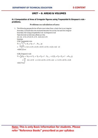
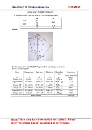
The document provides information on chain surveying, including:
1) It defines chain surveying and its objectives, which include measuring distances and establishing land boundaries.
2) It describes the various equipment used in chain surveying such as chains, tapes, pegs, arrows, ranging rods, and cross staffs.
3) It explains the different operations involved in chain surveying such as ranging, which can be direct or indirect, and using a line ranger or cross staff to measure perpendicular offsets.


![DEPARTMENT OF TECHNICAL EDUCATION E-CONTENT
Note: This is only Basic Information for students. Please
refer “Reference Books” prescribed as per syllabus
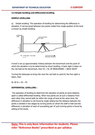
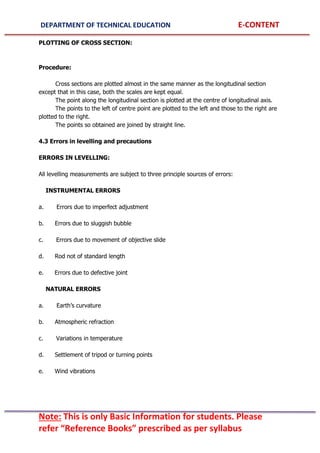
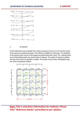
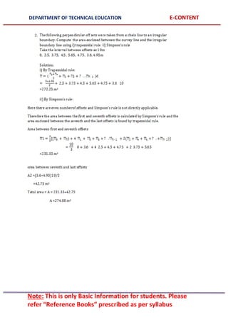
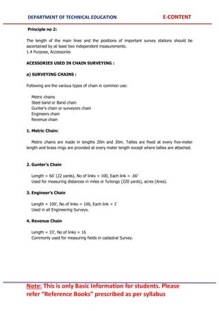
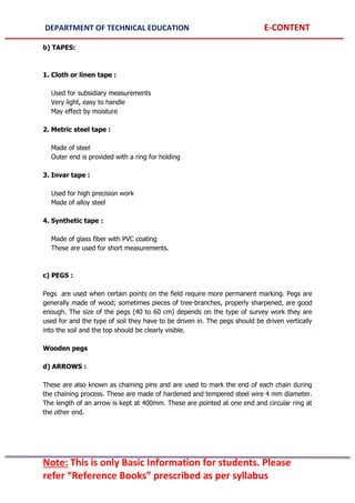
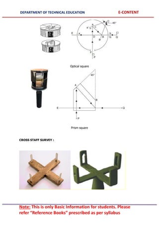
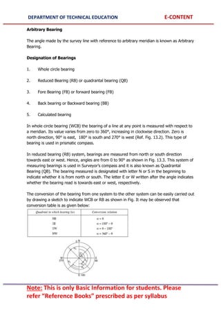
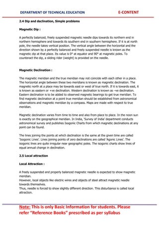
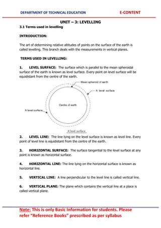
sight is checked to locate the object. With open cross staff (Fig.a) it is only possible to set
perpendicular, whereas with french cross staff (Fig (b)), even 45º angle may be set. Since
there are graduations and upper drum can be rotated over lower drum adjustable cross staff
can be also used to set any angle.
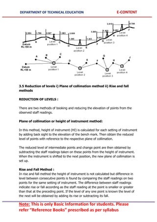
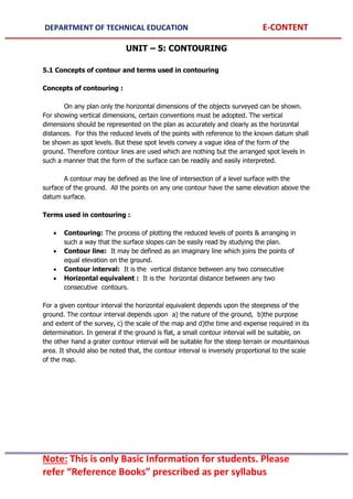
Perpendicular Offsets Using Optical Square and Prism Square :
These instruments are based on the optical principle that if two mirrors are at angle ‘θ’ to
each other, they reflect a ray at angle ‘2θ’. Figure 12.15 shows a typical optical square.
Optical square consists of a metal box about 50 mm in diameter and 125 mm deep. In the
rim of
the box there are three openings:
(i) a pin hole at E
(ii) a small rectangular slot at G, and
(iii) a large rectangular slot at F.
A and B are the two mirrors placed at 45º to each other. Hence the image of an object at F
which falls on A gets reflected and emerges at E which is at right angles to the line FA. The
mirror A which is opposite to the opening at F is fully silvered. It is fitted to a frame which is
attached to the bottom plate. If necessary this mirror can be adjusted by inserting a key on
the top of the cover. The mirror B which is in the line with EG is silvered in the top half and
plain in the bottom half. It is firmly attached to the bottom plate of the box. The ranging rod
at Q is directly sighted by eye at E in the bottom half of the B which is a plain glass. At the
same time in the top half of B, the reflected ray of the object at P is sighted. When the
image of P is in the same vertical line as the object at Q, then the lines PA is at right angles
to the line EB. This instrument can be used for finding foot of the perpendicular or to set a
right angle. In prism square, instead of two mirrors at 45º to each other a prism which has
two faces at 45º to each other is used [Fig. 1.10.]. Its advantage is it will not go out of
adjustment even after long usage.](https://image.slidesharecdn.com/15ce21t-220922052343-d8d69652/85/surveying-1-pdf-13-320.jpg)


![DEPARTMENT OF TECHNICAL EDUCATION E-CONTENT
Note: This is only Basic Information for students. Please
refer “Reference Books” prescribed as per syllabus
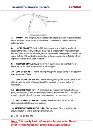
(c) Arbitrary Benchmark: In many engineering projects the difference in
elevations of neighbouring points is more important than their reduced level with
respect to mean sea level. In such cases a relatively permanent point, like plinth of a
building or corner of a culvert, are taken as benchmarks, their level assumed
arbitrarily such as 100.0 m, 300.0 m, etc.
(d) Temporary Benchmark: This type of benchmark is established at the end of
the day’s work, so that the next day work may be continued from that point. Such
point should be on a permanent object so that next day it is easily identified.
The adjustments to be made at every setting of the instrument are called temporary
adjustments.
TEMPORARY ADJUSTMENTS OF LEVEL :
The following three adjustments are required for the instrument whenever set over a
new point before taking a reading:
(i) Setting
(ii) Levelling
(iii) Focusing and Elimination of parallax
Setting :
Tripod stand is set on the ground firmly so that its top is at a convenient height.
Then the level is fixed on its top. By turning tripod legs radially or circumferentially,
the instrument is approximately levelled.
Some instruments are provided with a less sensitive circular bubble on tribrach for
this purpose.
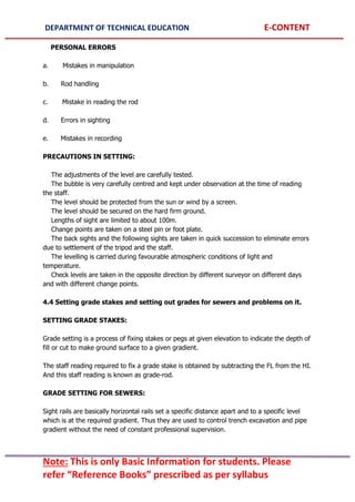
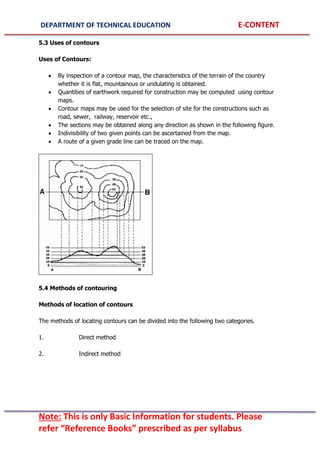
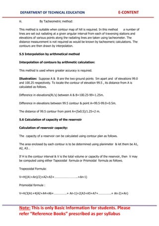
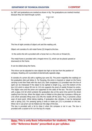
Levelling : The procedure of accurate levelling with three levelling screw is as given
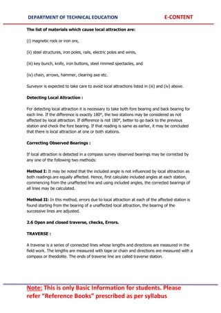
below:
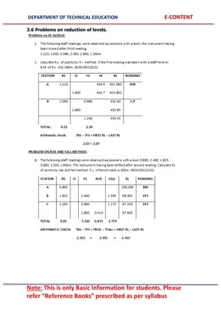
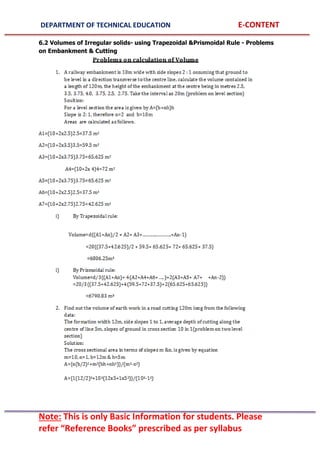
(i) Loosen the clamp and turn the telescope until the bubble axis is parallel to the
line joining any two screws [Ref. Fig. (a)].](https://image.slidesharecdn.com/15ce21t-220922052343-d8d69652/85/surveying-1-pdf-36-320.jpg)
![DEPARTMENT OF TECHNICAL EDUCATION E-CONTENT
Note: This is only Basic Information for students. Please
refer “Reference Books” prescribed as per syllabus
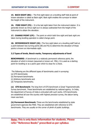
(ii) Turn the two screws inward or outward equally and simultaneously till bubble is
centred.
(iii) Turn the telescope by 90° so that it lies over the third screw [Fig. (b)] and level
the instrument by operating the third screw.
(iv) Turn back the telescope to its original position [Fig.(a)] and check the bubble.
Repeat steps (ii) to (iv) till bubble is centred for both positions of the telescope.
(v) Rotate the instrument by 180°. Check the levelling.
Focussing :
Focussing is necessary to eliminate parallax while taking reading on the staff. The
following two steps are required in focussing:
(i) Focussing the eyepiece: For this, hold a sheet of white paper in front of telescope
and rotate eyepiece in or out till the cross hairs are seen sharp and distinct.
(ii) Focussing the objective: For this telescope is directed towards the staff and the
focussing screw is turned till the reading appears clear and sharp.
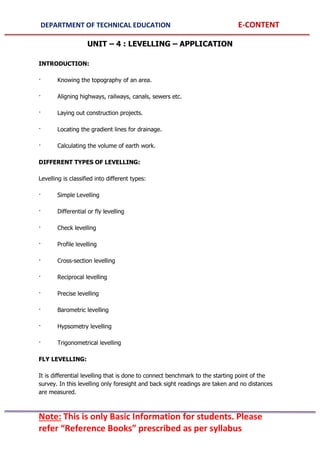
3.3 Concept of B.S, I.S, F.S, C.P, H.I and remarks
BACK SIGHT (BS) : The first sight taken on a levelling staff held at point of known
elevation is called as Back sight. Back sight enables the surveyor to obtain the height
of the instrument.
INTERMEDIATE SIGHT (IS) : The fore sight taken on a levelling staff held at a point
between two turning points (BS and FS) to determine the elevation of those points is
known as intermediate sight.
FORE SIGHT (FS) : It is the last sight taken from the instrument station. It is
generally known as minus sight as it is always subtracted from the height of the
instrument to obtain the elevation.
CHANGE POINT (CP) : The point on which both fore sight and back sight are taken
during levelling operation is called change point.
HEIGHT OF INSTRUMENT (HI) : The elevation of line of sight wrt the assumed
datum is known as height of instrument.
HI = BS + RL OF THE BM](https://image.slidesharecdn.com/15ce21t-220922052343-d8d69652/85/surveying-1-pdf-37-320.jpg)