This ppt presentation covers compass surveying, which explains principal of compass surveying, Types of compass, Difference between compass, Bearing, Definitions related to compass surveying etc.
Metric Chain : It Consists of galvanized mild steel wire of 4mm diameter known as link.
It is available in 20m, 30m, 50m length which consists of 100 links.
Gunter’s Chain : A 66 feet long chain consists of 100 links, each of 0.66 feet, it is known as Gunter’s chain.
This chain is suitable for taking length in miles.
Engineer’s Chain : A 100 feet long chain consisting of 100 links each of 1 feet is known as engineer’s chain.
This chain is used to measure length in feet and area in sq.yard.
Revenue Chain : it is 33 feet long chain consisting of 16 links.
This chain is used for distance measurements in feet & inches for smaller areas.
Introduction to surveying, ranging and chainingShital Navghare
This presentation contains the complete introduction of surveying. It also includes all the instrucments used in linear measurement and the terms related to Ranging and Chaining
Surveying is an important part of Civil engineering. Various part like theodolite, plane table surveying, computation of area and volume are useful for all university examination and other competitive examination
Compass surveying
Bearing
Whole circle bearing and reduced bearing
Conversion of bearings
Computation of angles
Declination and dip
Local attraction
Isogonic Lines
Agonic Lines
Detecting local attraction
For detecting local attraction it is necessary to take both fore bearing and back bearing for each line.
If the difference is exactly 180°, the two stations may be considered as not affected by local
attraction.
If difference is not 180°, better to go back to the previous station and check the fore bearing. If that
reading is same as earlier, it may be concluded that there is local attraction at one or both stations.
Upon completing the course, the students will be able to:
1. Define and state the scope of surveying and geomatics in civil engineering
2. Understand the basic principles of surveying and geomatics engineering
3. Apply the different methods of surveying and geomatics to measure the features of interest
4. Analyze the traditional and advanced methods of surveying
5. Evaluate the different techniques of surveying and geomatics in solving real world problems.
6. Design and construct solutions for real world problems related to surveying and geomatics.
Saudi Arabia stands as a titan in the global energy landscape, renowned for its abundant oil and gas resources. It's the largest exporter of petroleum and holds some of the world's most significant reserves. Let's delve into the top 10 oil and gas projects shaping Saudi Arabia's energy future in 2024.
Cosmetic shop management system project report.pdfKamal Acharya
Buying new cosmetic products is difficult. It can even be scary for those who have sensitive skin and are prone to skin trouble. The information needed to alleviate this problem is on the back of each product, but it's thought to interpret those ingredient lists unless you have a background in chemistry.
Instead of buying and hoping for the best, we can use data science to help us predict which products may be good fits for us. It includes various function programs to do the above mentioned tasks.
Data file handling has been effectively used in the program.
The automated cosmetic shop management system should deal with the automation of general workflow and administration process of the shop. The main processes of the system focus on customer's request where the system is able to search the most appropriate products and deliver it to the customers. It should help the employees to quickly identify the list of cosmetic product that have reached the minimum quantity and also keep a track of expired date for each cosmetic product. It should help the employees to find the rack number in which the product is placed.It is also Faster and more efficient way.
Student information management system project report ii.pdfKamal Acharya
Our project explains about the student management. This project mainly explains the various actions related to student details. This project shows some ease in adding, editing and deleting the student details. It also provides a less time consuming process for viewing, adding, editing and deleting the marks of the students.
NUMERICAL SIMULATIONS OF HEAT AND MASS TRANSFER IN CONDENSING HEAT EXCHANGERS...ssuser7dcef0
Power plants release a large amount of water vapor into the
atmosphere through the stack. The flue gas can be a potential
source for obtaining much needed cooling water for a power
plant. If a power plant could recover and reuse a portion of this
moisture, it could reduce its total cooling water intake
requirement. One of the most practical way to recover water
from flue gas is to use a condensing heat exchanger. The power
plant could also recover latent heat due to condensation as well
as sensible heat due to lowering the flue gas exit temperature.
Additionally, harmful acids released from the stack can be
reduced in a condensing heat exchanger by acid condensation. reduced in a condensing heat exchanger by acid condensation.
Condensation of vapors in flue gas is a complicated
phenomenon since heat and mass transfer of water vapor and
various acids simultaneously occur in the presence of noncondensable
gases such as nitrogen and oxygen. Design of a
condenser depends on the knowledge and understanding of the
heat and mass transfer processes. A computer program for
numerical simulations of water (H2O) and sulfuric acid (H2SO4)
condensation in a flue gas condensing heat exchanger was
developed using MATLAB. Governing equations based on
mass and energy balances for the system were derived to
predict variables such as flue gas exit temperature, cooling
water outlet temperature, mole fraction and condensation rates
of water and sulfuric acid vapors. The equations were solved
using an iterative solution technique with calculations of heat
and mass transfer coefficients and physical properties.
We have compiled the most important slides from each speaker's presentation. This year’s compilation, available for free, captures the key insights and contributions shared during the DfMAy 2024 conference.
Welcome to WIPAC Monthly the magazine brought to you by the LinkedIn Group Water Industry Process Automation & Control.
In this month's edition, along with this month's industry news to celebrate the 13 years since the group was created we have articles including
A case study of the used of Advanced Process Control at the Wastewater Treatment works at Lleida in Spain
A look back on an article on smart wastewater networks in order to see how the industry has measured up in the interim around the adoption of Digital Transformation in the Water Industry.
CW RADAR, FMCW RADAR, FMCW ALTIMETER, AND THEIR PARAMETERSveerababupersonal22
It consists of cw radar and fmcw radar ,range measurement,if amplifier and fmcw altimeterThe CW radar operates using continuous wave transmission, while the FMCW radar employs frequency-modulated continuous wave technology. Range measurement is a crucial aspect of radar systems, providing information about the distance to a target. The IF amplifier plays a key role in signal processing, amplifying intermediate frequency signals for further analysis. The FMCW altimeter utilizes frequency-modulated continuous wave technology to accurately measure altitude above a reference point.
CW RADAR, FMCW RADAR, FMCW ALTIMETER, AND THEIR PARAMETERS
Compass surveying
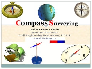
1. R a k e s h K u m a r V e r m a
A s s i s t a n t P r o f e s s o r ,
C i v i l E n g i n e e r i n g D e p a r t m e n t , P . I . E . T .
P a r u l U n i v e r s i t y
Compass Surveying
2. Definitions
True Meridian
True Bearing /Azimuth
Magnetic Meridian
Magnetic Bearing /Bearing
Arbitrary Meridian
Arbitrary Bearing.
Grid Meridian
Grid Bearing
8. (i) Whole Circle Bearing
(WCB)
(ii) Quadrantal Bearing
(QB)
WCB QB
Designation of Magnetic Bearing
O
NN
W
SS
E EW
SE
NW
SW
NE
O O
A
B
A
B
Clockwise rotation has to be followed
9. Reduced Bearing (RB) Fore And Back Bearing
Similar to Quadrant
Bearing
Obtained when,
Depended on direction
of main survey line
Bearing
WCB QBConvert
N
Direction of Survey
BM
A B
BB FB
North
13. Fore Bearing & Back Bearing
Bearing taken in forward direction of survey line-
FB
Bearing taken in backward direction of survey
line- BB
FB
BB
A
B
B
A
14. Magnetic Declination
The Horizontal Angle Between the Magnetic
Meridian and True Meridian is known as
‘magnetic declination’.
When the north end of the magnetic needle is
pointed towards the west side of the true meridian,
the position is termed ‘Declination West’ ().
When the north end of the magnetic needle is
pointed towards the east side of the true meridian,
the position is termed ‘Declination East’
16. Isogonic and Agonic Lines
Lines Passing Through Points Of Equal
Declination are known as ‘isogonic’ lines.
The Survey of India Department has prepared a map
of India in which the isogonic and agonic lines are
shown properly as a guideline to conduct the
compass survey in different parts of the country.
20. Local Attraction
Error introduced in direction of magnetic needle due to
magnetic materials such as iron ore, steel structures,
electric cables conveying current; etc.
Then it does not show the actual north. This
phenomenon is known as ‘local attraction’.
If
Error compensation
Divide equally in FB & BB
Error of local attractionFB-BB≠ 180 degrees
FB-BB= 180 degrees Free from local attraction
21. Example
For example, consider the case when
Observed FB of AB = 60030’
Observed BB of AB = 24000’
Calculated BB of AB = 600300 + 18000’ = 240030’
Corrected BB of AB = 1/2 (24000’ + 240030’) = 240015’
Hence, Corrected FB of AB = 240015’ – 18000’ = 60015’
22. Principle of Compass Surveying
Traversing, which Involves A Series of Connected Lines.
The magnetic bearings of the lines are measured by prismatic
compass and
The distances of the lines are measured by chain.
Such survey does not require the formation of a network of
triangles.
Interior details are located by taking offsets from the main survey
lines. Sometimes subsidiary lines may be taken for locating these
details.
Compass surveying is not recommended for areas where local
attraction is suspected due to the presence of magnetic substances
like steel structures, iron ore deposits, electric cables conveying
current, and so on.
23. TRAVERSING
Well Defined Network of Connected Lines
The sides of the traverse are known as ‘traverse legs’.
Measurements
A traverse may be of two types –
Closed traverse
1. closed loop (i.e. when the finishing point coincides with the starting
point
Open traverse
1. connected lines extends along a general direction and does not return to
the starting point,
2. Open traverse is suitable for the survey of roads, rivers, coast lines, etc
Lengths of Lines
Directions
Chain
Compass or Theodolite
24. Methods of Traversing
Chain traversing (by chain angle)
Compass traversing (by free needle)
Theodolite traversing (by fast needle) and
Plane table traversing (by plane table)
25. Check on Angular Measurements
(a) The sum of the measured Interior Angles should be
equal to (2N – 4) x 90ᵒ where N is the number of sides of
the traverse.
(b) The sum of the measured Exterior Angles should be
equal to (2N + 4) x 90ᵒ
(c) The algebraic sum of the Deflection Angles should be
equal to 360ᵒ
Right-hand deflection is considered positive and left-hand
deflection negative.
26. Check on Linear Measurement
(a) The lines should be measurement once each on two
different days (along opposite directions). Both
measurements should tally.
(b) Linear measurements should also be taken by the
stadia method. The measurements by chaining and by
the stadia method should tally.
27. Check on Open Traverse
No Direct checks available, but following
methods can be adopted
1. Taking cut-off lines
2. Taking an auxiliary point
28. A
F
E
C
D
B
N
N
N
N
N
For Check
Taking Cut-off Lines
Cut-off lines are taken between some intermediate stations of the open traverse.
Let AD and DG be the cut-off lines. The lengths and magnetic bearings of the cut-off
lines are measured accurately. After plotting the traverse, the distances and bearings
are noted from the map. These distances and bearings should tally with the actual
records from the field
29. Taking an Auxiliary Point
A
D
C
B
E
P
N
N
N
N
N
A permanent point ‘P’ is selected on one side of it. If the survey is carried out
accurately and so is the plotting, all the measured bearings of P when plotted should
meet at the point P. The permanent point P is known as the ‘auxiliary point’
33. Sr.
No.
Base Of
Comparison Prismatic Compass Surveyor Compass
1 First look Prism at one end and slit on
other
No prism only Slit at both
end
2 Use of Tripod
Stand
May or may not use along,
Steady hold in hand also give
good results
Use of Tripod stand is
necessary
3 Observation/
Readings
Taken with help of prism
provided by eye slit
Directly read from top of
compass
4 Magnetic
Needle
Does not act as index Act as index
5 Graduation WCB system QB system
6 Graduation
marking
Appear inverted from top,
Zero at south & 180 degrees
at north
Mark directly Zero at North
and 90 degree at East
7 Graduated
circle
Attached with needle, Does
not rotate with line of sight
Permanently attached with
box, rotates with line of sight
Comparison between
Prismatic Compass and Surveyor Compass
34. Temporary Adjustment of Compass
Centering
Levelling
Focusing
1. Adjustment of prism
2. Bisecting/Observation of bearing