Power flow through overhead transmission lines is limited by concerns over electrical phase shift, voltage drop, and thermal effects. Specifically:
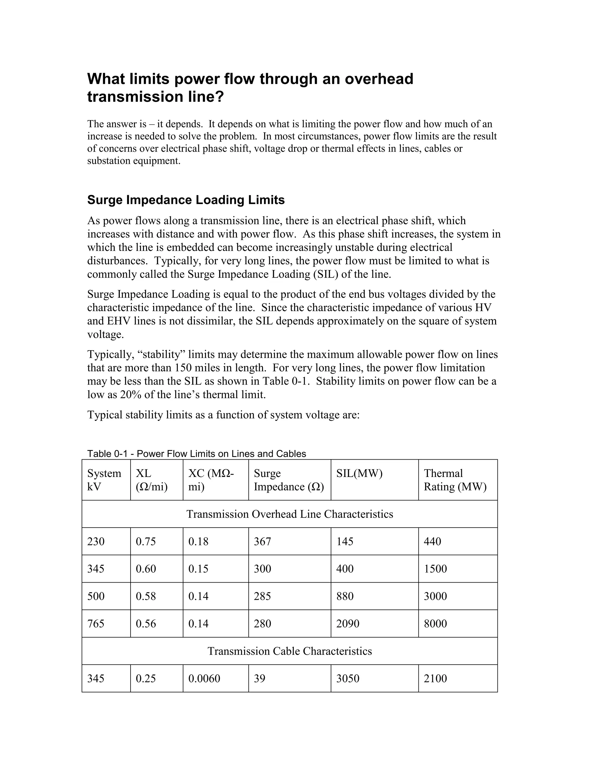
- Surge impedance loading limits power flow to prevent excessive phase shift, which can cause instability. This limit depends on system voltage and transmission line characteristics.
- Voltage drop limits power flow to maintain voltage levels within 5-10% of the sending voltage. This usually limits lines 50-150 miles long.
- Thermal limits prevent overheating of conductors and maintain structural integrity. This usually determines the limit for lines under 50 miles. Longer lines are limited by phase shift or voltage drop first.