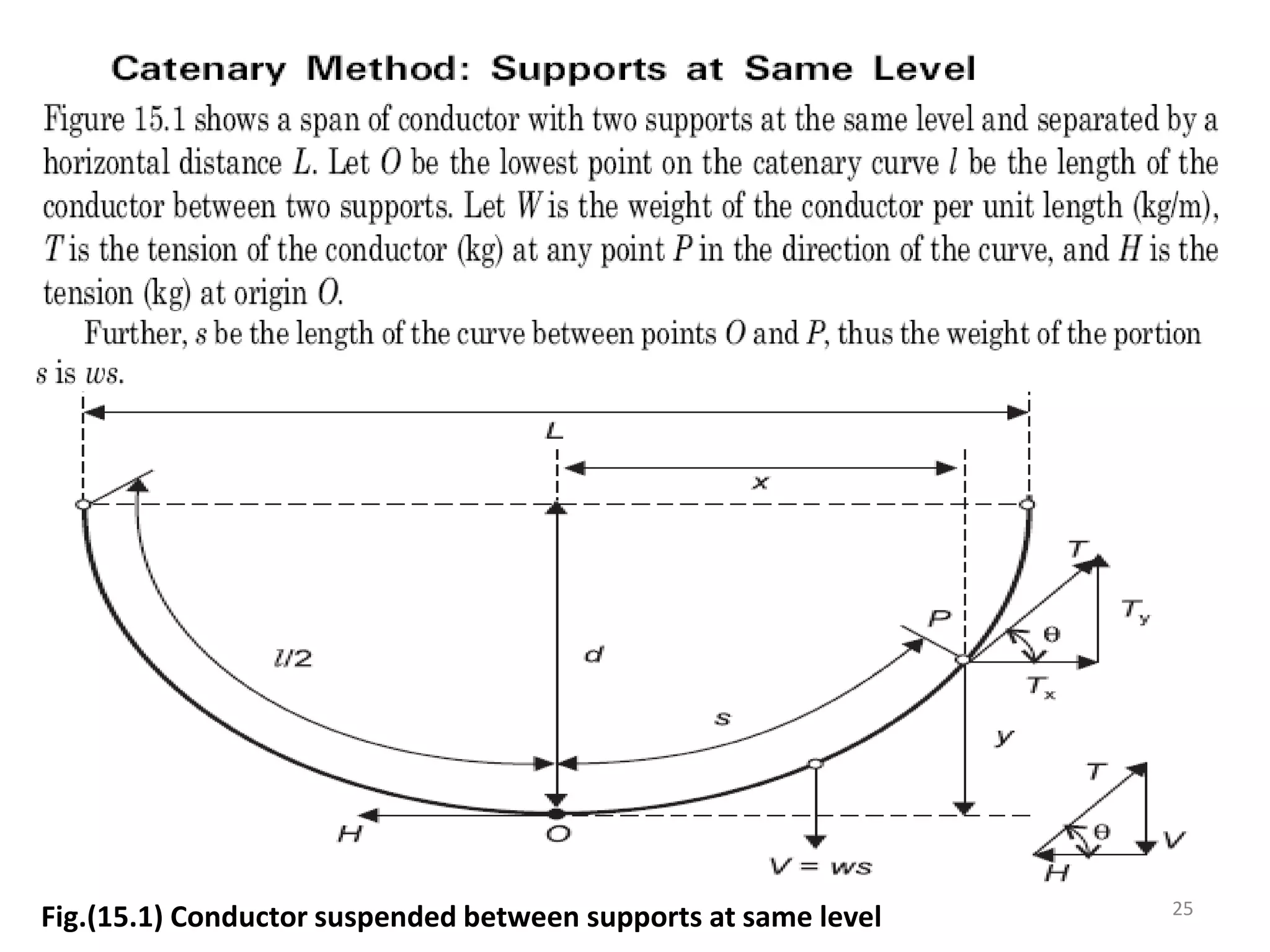
This chapter discusses the mechanical design of transmission lines. It covers various topics such as types of conductors, line supports, spacing between conductors, and sag-tension calculations. The key conductors mentioned are copper, aluminum, and steel. Wooden poles, steel tubular poles, reinforced concrete poles, and steel towers are described as the main types of line supports. The document also discusses the effects of wind and ice loading on transmission lines. Sag-tension calculations are explained using catenary curve equations.

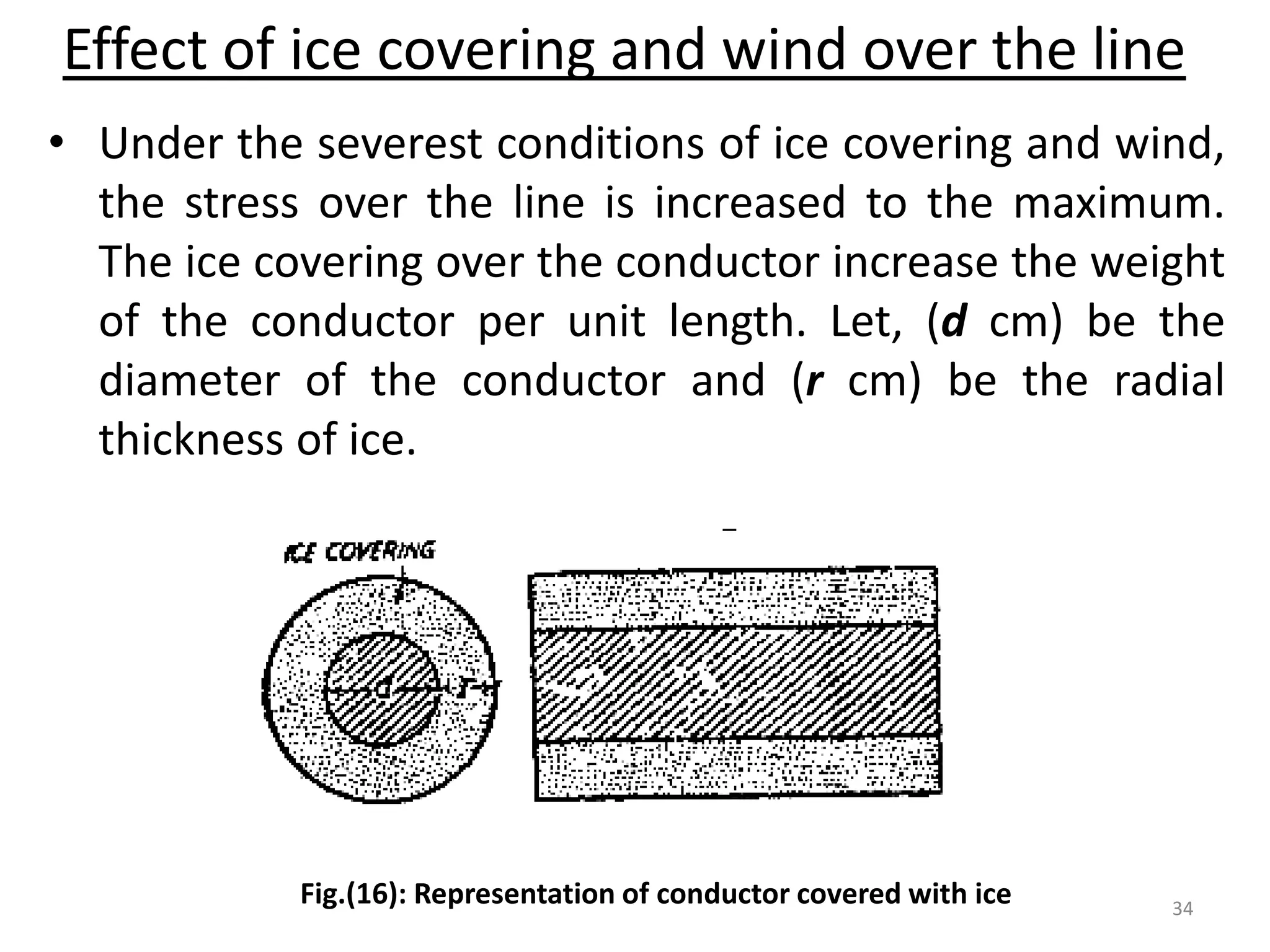
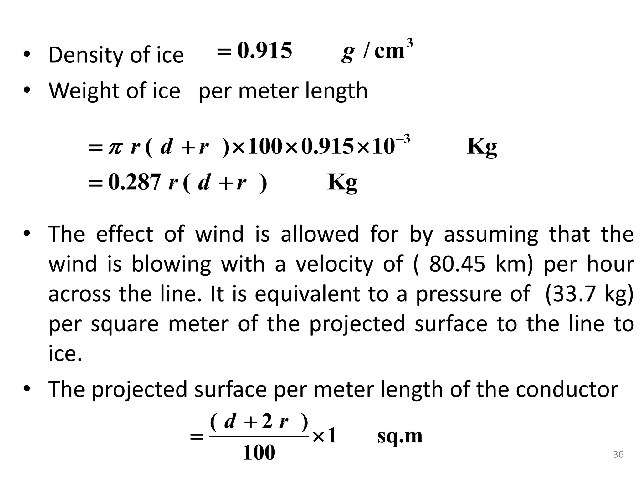
![• Cross-sectional area of the conductor
• Overall cross-sectional area when covered with ice
• Sectional area of the ice
2
4
d
2
( 2 )
4
d r
2
2
2 2
2 2 2
= ( 2 )
4 4
= [ ( 2 ) ]
4
= [ 4 4 ]
4
= ( )
d
d r
d r d
d r d r d
r d r
35](https://image.slidesharecdn.com/chapter4-mechanicaldesignoftransmissionlines-220125185634/75/Chapter-4-mechanical-design-of-transmission-lines-35-2048.jpg)