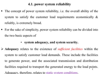
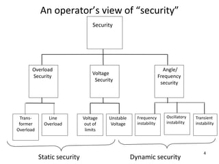
SlideShare a Scribd company logo
1 of 44
Outlines
4.1 power system reliability and quality
4.2 Reliability assessment techniques
4.3 Reliability indices
1
2
4.1. power system reliability
 The concept of power system reliability, i.e. the overall ability of the
system to satisfy the customer load requirements economically &
reliably, is extremely broad.
 For the sake of simplicity, power system reliability can be divided into
the two basic aspects of
• system adequacy, and system security.
 Adequacy relates to the existence of sufficient facilities within the
system to satisfy customer load demands. These include the facilities
to generate power, and the associated transmission and distribution
facilities required to transport the generated energy to the load points.
Adequacy, therefore, relates to static system conditions.
……Conty’
• Security pertains to the response of the system to the
disturbances it is subjected to.
• These may include conditions associated with local and
widespread disturbances and loss of major
generation/transmission.
• Most of the techniques presently available are in the domain
of adequacy assessment.
3
4
An operator’s view of “security”
Security
Overload
Security
Voltage
Security
Angle/
Frequency
security
Trans-
former
Overload
Line
Overload
Voltage
out of
limits
Unstable
Voltage
Frequency
instability
Transient
instability
Oscillatory
instability
Static security Dynamic security
5
Other Views of “Security”
Security = dynamic security
Adequacy = static security
Protection engineers use the word “security” to refer to the
“degree of certainty that a relay or relay system will not
operate incorrectly.”
6
System Dynamic Performance
In designing and operating the interconnected power network,
system dynamic performance is taken into account because:
• The power system is subjected to changes (small and large). It is
important that when the changes are completed, the system
settles to new operating conditions such that no constraints are
violated.
• Not only should the new operating conditions be acceptable (as
revealed by steady-state analysis) but also the system must
survive the transition to these conditions. This requires
dynamic analysis.
 ONE ASPECT OF SYSTEM SECURITY IS THE
ABILITY OF THE SYSTEM TO “STAY TOGETHER.”
 THE KEY IS THAT THE GENERATORS CONTINUE
TO OPERATE “IN SYNCHRONISM,” OR NOT TO
“LOSE SYNCHRONISM” OR NOT TO “GO OUT OF
STEP.” THIS IS THE PROBLEM OF
“POWER SYSTEM STABILITY”
7
8
Importance of Power System Stability
• Generators must be kept in synchronism; if their relative
motion begins to change too much, uncontrollable
oscillations may appear in the grid causing damage to
equipment, particularly generators.
• Therefore, relays are used to detect this condition and trip
generators before the damage occurs. Although tripping
prevents the damage, it results in under-frequency, and
possibly load interruption, and in the worst case, cascading
outages and blackout.
9
• Power System: A network of one or more electrical
generating units, loads, and/or power transmission lines,
including the associated equipment electrically or
mechanically connected to the network.
• Operating Quantities of a Power System: Physical
quantities, measured or calculated, that can be used to
describe the operating conditions of a power system.
• Operating quantities include real, reactive, and apparent
powers, & rms phasors of alternating voltages &
currents.
………..Cont’
• Steady-State Operating Condition of a Power System:
 An operating condition of a power system in which all the
operating quantities that characterize it can be considered to be
constant for the purpose of analysis.
• Synchronous Operation:
 A machine is in synchronous operation with a network or
another machine(s) to which it is connected if its average
electrical speed (product of its rotor angular velocity and the
number of pole pairs) equals the angular frequency of the ac
network or the electrical speed of the other machine(s).
10
11
………..Cont’s
 A power system is in synchronous operation if all its
connected synchronous machines are in synchronous
operation with the ac network and with each other.
• Asynchronous or nonsynchronous operation:
Asynchronous Operation of a Machine: A machine
is in asynchronous operation with a network or
another machine to which it is connected if it is not
in synchronous operation.
12
……Cont’
 A power system is in asynchronous operation if one or more
of its connected synchronous machines are in asynchronous
operation.
. Disturbance in a Power System: A disturbance in a power
system is a sudden change or a sequence of changes in one or
more parameters of the system, or in one or more of the
operating quantities.
13
… cont’
 Small Disturbance In a Power System: It is a disturbance
for which the equations that describe the dynamics of the
power system may be linearized for the purpose of accurate
analysis.
 Large Disturbance In a Power System: It is a disturbance
for which the equations that describe the dynamics of the
power system cannot be linearized for the purpose of
accurate analysis.
14
Differences between reliability, security, and stability
• Reliability is the overall objective in power system design and
operation. To be reliable, the power system must be secure most
of the time.
• To be secure, the system must be stable but must also be secure
against other contingencies that would not be classified as
stability problems e.g., damage to equipment such as an
explosive failure of a cable, fall of transmission towers due to ice
loading or sabotage. As well, a system may be stable following a
contingency, yet insecure due to post-fault system conditions
resulting in equipment overloads or voltage violations.
… Cont’
• System security may be further distinguished from stability in
terms of the resulting consequences. For eg., two systems may
both be stable with equal stability margins, but one may be
relatively more secure b/c the consequences of instability are less
severe.
• Security & stability are time-varying attributes w/c can be
judged by studying the performance of the power systems under a
particular set of conditions.
• Reliability is a function of the time-average performance of the
power system; it can only be judged by consideration of the
15
16
4.2. Power Quality
The term “unprotected power” refers to electric power, voltage
or current waveforms containing other than desired components.
These voltage and current components contaminate and distort
the ideal waveform. They can be caused by:
• Electric switching (digital) devices including switch-mode
power supplies.
• Arcing devices including fluorescent lamps and welders.
• Deteriorated wiring, connections or ground currents.
• Weak, overloaded power supplies. 17
……Cont’
. Various system design problems including transformer saturation
from geomagnetically induced currents.
Electrical distortion is typically characterized as:
 Noise, Harmonics, Transients and various other short-term
and long-term disturbances.
How we minimize or eliminate some distortions? Using
Surge arresters, electromagnetic shields, isolation transformers,
constant voltage regulators, tap-changing regulators, low-
impedance power conditioners, proper grounding and electrical
maintenance programs
18
Electrical distortion
1. Noise:
• Unpredictable, random, unwanted signals superimposed on data
signals or on power waveforms is called noise.
• In a power system, electrical noise is generally a long series of
relatively high-frequency impulses having varying amplitudes and
riding on the power waveform.
 Interference affects data signals;
 Static affects radio signals. B/c noise can affect equipment operation,
noise makes power and control systems, such as programmable logic
controllers, less reliable.
• In technical terms, noise is electromagnetic interference (EMI) and
19
2. Harmonics
• Electrically, a harmonic is a voltage/current whose waveform cycles
at a frequency that is an integer-multiple of the desired or
fundamental frequency (odd harmonics especially third order).
• Harmonics are caused by the use of variable-speed drives,
rectifiers, inductive heaters, personal computers, saturated
transformers (fluorescent lighting ballasts), copying machines,
solid state switches, fluorescent and high intensity discharge arc
lamps & other nonlinear/arcing devices.
• Harmonics contaminate the sinusoidal power supply waveform.
• The distorted waveform caused by harmonics is a repeating, non-
20
• Harmonic analyzers are test sets that determine all necessary
measurements and calculate waveform distortion.
• Less expensive instruments reading only voltage for the selected
harmonics can be used along with manual calculations to determine
the same information.
• Total Harmonic Distortion (THD) is the overall level of harmonic
distortion of a voltage waveform.
• The THD of a voltage waveform can be calculated by the formula:
21
Even harmonics usually do not appear in a properly operating
power system.
Linear Voltage / Current
No Harmonic Content
voltage
current
Non-Linear Voltage / Current
Harmonic Content
voltage
current
Non - Linear Load
"A load where the waveshape of the steady-
state current does not follow the waveshape
of the applied voltage."
voltage
current
3. Transients
• Transients are surges/changes in steady-state voltage/current that
disappear as a new steady state condition is reached. Typically these
rapid electrical changes, usually lasting milliseconds or microseconds,
transfer readily b/n circuits through electromagnetic coupling.
• A pulse (impulse/spike) usually lasts less than 2 milliseconds and is a
short duration transient where the initial & final steady-state
conditions of the system are usually the same.
• The causes of transients include lightning, restoring power following
an interruption, routine switching, loose wires & electrical breakdown
and other fault conditions.
25
4. Other Electrical distortion
• Power conditioning equipment combines voltage regulation with
power system isolation and shielding.
• UPSs are generally an excellent way to control power
distortions, but their primary purpose is to improve power
reliability not to clean poor power quality.
• Short-term power quality disturbances include dropouts, sags
and swells.
 Dropouts are momentary power losses typically occurring
within one electrical cycle.
26
RMS Voltage Variations
-200
-150
-100
-50
0
50
100
150
200
Sag Swell Interruption
………..Cont’
 Sags are depletions of power caused when heavy loads are
started or connected.
 Swells are power surges caused by sudden load disconnects.
 Sags and swells are typically seen as voltage changes lasting 2.5
seconds (150 cycles for a 60 Hz system or 125 cycles for a 50
Hz system ) or less upon sudden changes in power demand.
28
4.3. Reliability assessment techniques
1. Generating System Reliability Assessment
 Generating capacity reliability is defined in terms of the
adequacy of the installed generating capacity to meet the
system load demand.
 Outages of generating units and/or load in excess of the
estimates could result in “loss of load”, i.e., the available
capacity (installed capacity - capacity on outage) being
inadequate to supply the load.
29
….Cont’
 In general, this condition requires emergency assistance
from neighboring systems and emergency operating
measures such as system voltage reduction and voluntary
load curtailment.
 Depending on the shortage of the available capacity, load
shedding may be initiated as the final measure after the
emergency actions. The conventional definition of “loss of
load” includes all events resulting in negative capacity
margin or the available capacity being less than the load.
30
…….Cont’
 The basic methodology for evaluating generating system
reliability is to develop probability models for capacity on
outage and for load demand, and calculate the probability
of loss of load by a convolution of the two models.
 This calculation can be repeated for all the periods (e.g.,
weeks) in a year considering the changes in the load
demand, planned outages of units, and any unit additions or
retirements, etc.
31
Probabilistic Criteria and Indices
An understanding of the probabilistic criteria and indices used in
generating capacity reliability studies is important. These include
1. loss of load probability (LOLP)
2. loss of load expectation (LOLE)
3. loss of energy expectation (LOEE)/expected energy not supplied
(EENS)
4. frequency & duration (F&D) indices
5. energy index of reliability (EIR)
6. energy index of unreliability (EIU), and
7. system minutes (SM). 32
 loss of load probability (LOLP):
• This is the oldest and the most basic probabilistic index. It is defined
as the probability that the load will exceed the available generation.
Its weakness is that it defines the likelihood of encountering trouble
(loss of load) but not the severity; for the same value of LOLP, the
degree of trouble may be less than 1 MW or greater than 1000 MW or
more. Therefore it cannot recognize the degree of capacity or energy
shortage.
• This index has been superseded by one of the following expected
values in most planning applications because LOLP has less physical
significance and is difficult to interpret.
33
• Loss of load expectation (LOLE):
• This is now the most widely used probabilistic index in deciding
future generation capacity.
• It is generally defined as the average number of days/hours on which
the daily peak load is expected to exceed the available capacity.
• It therefore indicates the expected number of days (or hours) for
which a load loss or deficiency may occur.
• This concept implies a physical significance not forthcoming from
the LOLP, although the two values are directly related.
• It has the same weaknesses that exist in the LOLP.
34
Loss of energy expectation (LOEE)
 This index is defined as the expected energy not supplied
(EENS) due to those occasions when the load exceeds the
available generation.
 It is presently less used than LOLE but is a more appealing index
since it encompasses severity of the deficiencies as well as their
likelihood.
 It therefore reflects risk more truly and is likely to gain
popularity as power systems become more energy-limited due to
reduced prime energy and increased environmental controls.
35
Energy index of reliability (EIR) and Energy index of
unreliability (EIU)
 These are directly related to LOEE which is normalized by
dividing by the total energy demanded.
 This basically ensures that large and small systems can be
compared on an equal basis and chronological changes in a
system can be tracked.
36
Frequency & Duration (F&D) Indices
• The F&D criterion is an extension of LOLE and identifies
expected frequencies of encountering deficiencies and their
expected durations.
• It therefore contains additional physical characteristics but,
although widely documented, is not used in practice.
• This is due mainly to the need for additional data and
greatly increased complexity of the analysis without having
any significant effect on the planning decisions.
37
38
Distribution System Reliability Assessment
Load Point Indices
• failure rate, 
• average outage time, r
• average annual unavailability, U = .r
• average load disconnected, L
• expected energy not supplied, E = U.L
39
n
i
i 1
=



Interruptionfrequencyf [interruptions/year]
s
n
i i
i=1
n
i
i=1
r
=




Interruptiondurationr [hours/interruption]
s
n
i i
i=1
r
=


U
navailabilityqs 8760
Distribution System Reliability Assessment
40
System Oriented Reliability Indices, Number of
Interruptions
• Weighting by number of customers
– System Average Interruption Frequency Index SAIFI:
tot
n
i i
i=1
n
i
i=1
f N
N


S
A
IFI= (interruptions/year)
fi = number of interruptions at load point i
Ni = number of customers connected to load point i
n = number of load points interrupted
ntot = total number of load points
41
System Oriented Reliability Indices, Annual Interruption Time
• Weighting by number of customers
– System Average Interruption Duration Index SAIDI:
tot tot
n n
i i i i i
i=1 i=1
n n
i i
i=1 i=1
U N f r N
=
N N
 
 
S
A
ID
I= (hours/year)
Ui = firi = annual outage time for load point i
ri = Average outage duration for load point i
Distribution System Reliability Assessment
42
System Oriented Reliability Indices, Average Interruption Duration
• Weighting by number of customers
– Customer Average Interruption Duration Index CAIDI:
tot
n
i i
i=1
n
i i
i=1
U N
f N


C
A
ID
I= (hours/interruption)
SAIFI  CAIDI = SAIDI
tot tot tot tot
n n n n
i i i i i i i i i
i=1 i=1 i=1 i=1
n n n n
i i i i i
i=1 i=1 i=1 i=1
f N U N U N f r N
= =
N f N N N

   
   
Distribution System Reliability Assessment
43
System Oriented Reliability Indices, Unavailability, Energy Not
Supplied
• Average Service Unavailability Index
SAID
I
ASU
I=
8760
• Energy Not Supplied
n
av(i) i
i=1
P U

E
N
S= (kW
h/year)
P =A
verageloadconnectedtoloadpointi
av(i)
• Average Energy Not Supplied
tot
n
i
i=1
N

E
N
S
A
E
N
S= (kW
h/custom
er.year)
Distribution System Reliability Assessment
44

More Related Content

What's hot

A presentation on power system reliability
A presentation on power system reliabilityA presentation on power system reliability
A presentation on power system reliabilityKaransinh Parmar
 
Introduction of wide area mesurement syatem
Introduction of wide area mesurement syatemIntroduction of wide area mesurement syatem
Introduction of wide area mesurement syatemPanditNitesh
 
High Voltage Dc (HVDC) transmission
High Voltage Dc (HVDC) transmissionHigh Voltage Dc (HVDC) transmission
High Voltage Dc (HVDC) transmissionZunAib Ali
 
Interconnection issue in microgrid
Interconnection issue in microgridInterconnection issue in microgrid
Interconnection issue in microgridAmarjeet S Pandey
 
Loading Capability Limits of Transmission Lines
Loading Capability Limits of Transmission LinesLoading Capability Limits of Transmission Lines
Loading Capability Limits of Transmission LinesRaja Adapa
 
24620708 feeder-protection (1)
24620708 feeder-protection (1)24620708 feeder-protection (1)
24620708 feeder-protection (1)Adarsh Verma
 
INTRODUCTION TO POWER SYSTEM STABILITY BY Kundur Power Systems Solutions
INTRODUCTION TO POWER SYSTEM STABILITY BY Kundur Power Systems SolutionsINTRODUCTION TO POWER SYSTEM STABILITY BY Kundur Power Systems Solutions
INTRODUCTION TO POWER SYSTEM STABILITY BY Kundur Power Systems SolutionsPower System Operation
 
1.9 protection of power system
1.9 protection of power system1.9 protection of power system
1.9 protection of power systemW3Edify
 
Multi terminal dc systems (mtdc)
Multi terminal dc systems (mtdc)Multi terminal dc systems (mtdc)
Multi terminal dc systems (mtdc)jawaharramaya
 
Basics of AC transmission
Basics of AC transmissionBasics of AC transmission
Basics of AC transmissionSonuKumarBairwa
 
Phasor measurement unit and it's application ppt
Phasor measurement unit and it's application pptPhasor measurement unit and it's application ppt
Phasor measurement unit and it's application pptKhurshid Parwez
 
Doubly fed-induction-generator
Doubly fed-induction-generatorDoubly fed-induction-generator
Doubly fed-induction-generatorHarshad Karmarkar
 
20EEE659T - UNIT - 2 - POWER SYSTEM PLANNING AND RELIABILITY.pptx
20EEE659T - UNIT - 2 - POWER SYSTEM PLANNING AND RELIABILITY.pptx20EEE659T - UNIT - 2 - POWER SYSTEM PLANNING AND RELIABILITY.pptx
20EEE659T - UNIT - 2 - POWER SYSTEM PLANNING AND RELIABILITY.pptxthanigaivelraja1
 
Power quality disturbances
Power quality disturbancesPower quality disturbances
Power quality disturbancesManasKumarPatro
 
Review of different Fault Ride through (FRT) Control Strategies for a DFIG Wi...
Review of different Fault Ride through (FRT) Control Strategies for a DFIG Wi...Review of different Fault Ride through (FRT) Control Strategies for a DFIG Wi...
Review of different Fault Ride through (FRT) Control Strategies for a DFIG Wi...IRJET Journal
 

What's hot (20)

A presentation on power system reliability
A presentation on power system reliabilityA presentation on power system reliability
A presentation on power system reliability
 
Introduction of wide area mesurement syatem
Introduction of wide area mesurement syatemIntroduction of wide area mesurement syatem
Introduction of wide area mesurement syatem
 
Computer Application in Power system chapter one - introduction
Computer Application in Power system chapter one - introductionComputer Application in Power system chapter one - introduction
Computer Application in Power system chapter one - introduction
 
Power Quality
Power QualityPower Quality
Power Quality
 
Neutral grounding
Neutral groundingNeutral grounding
Neutral grounding
 
High Voltage Dc (HVDC) transmission
High Voltage Dc (HVDC) transmissionHigh Voltage Dc (HVDC) transmission
High Voltage Dc (HVDC) transmission
 
Interconnection issue in microgrid
Interconnection issue in microgridInterconnection issue in microgrid
Interconnection issue in microgrid
 
Loading Capability Limits of Transmission Lines
Loading Capability Limits of Transmission LinesLoading Capability Limits of Transmission Lines
Loading Capability Limits of Transmission Lines
 
24620708 feeder-protection (1)
24620708 feeder-protection (1)24620708 feeder-protection (1)
24620708 feeder-protection (1)
 
INTRODUCTION TO POWER SYSTEM STABILITY BY Kundur Power Systems Solutions
INTRODUCTION TO POWER SYSTEM STABILITY BY Kundur Power Systems SolutionsINTRODUCTION TO POWER SYSTEM STABILITY BY Kundur Power Systems Solutions
INTRODUCTION TO POWER SYSTEM STABILITY BY Kundur Power Systems Solutions
 
1.9 protection of power system
1.9 protection of power system1.9 protection of power system
1.9 protection of power system
 
Multi terminal dc systems (mtdc)
Multi terminal dc systems (mtdc)Multi terminal dc systems (mtdc)
Multi terminal dc systems (mtdc)
 
Basics of AC transmission
Basics of AC transmissionBasics of AC transmission
Basics of AC transmission
 
Power quality
Power qualityPower quality
Power quality
 
Power system security
Power system security Power system security
Power system security
 
Phasor measurement unit and it's application ppt
Phasor measurement unit and it's application pptPhasor measurement unit and it's application ppt
Phasor measurement unit and it's application ppt
 
Doubly fed-induction-generator
Doubly fed-induction-generatorDoubly fed-induction-generator
Doubly fed-induction-generator
 
20EEE659T - UNIT - 2 - POWER SYSTEM PLANNING AND RELIABILITY.pptx
20EEE659T - UNIT - 2 - POWER SYSTEM PLANNING AND RELIABILITY.pptx20EEE659T - UNIT - 2 - POWER SYSTEM PLANNING AND RELIABILITY.pptx
20EEE659T - UNIT - 2 - POWER SYSTEM PLANNING AND RELIABILITY.pptx
 
Power quality disturbances
Power quality disturbancesPower quality disturbances
Power quality disturbances
 
Review of different Fault Ride through (FRT) Control Strategies for a DFIG Wi...
Review of different Fault Ride through (FRT) Control Strategies for a DFIG Wi...Review of different Fault Ride through (FRT) Control Strategies for a DFIG Wi...
Review of different Fault Ride through (FRT) Control Strategies for a DFIG Wi...
 

Similar to CHAPTER- 4.ppt

Interconnection power system
Interconnection power systemInterconnection power system
Interconnection power systemNovia Putri
 
EE554Introductrion power sytability .ppt
EE554Introductrion power sytability .pptEE554Introductrion power sytability .ppt
EE554Introductrion power sytability .pptkifle203
 
Ppt on introduction to power quality
Ppt on introduction to power qualityPpt on introduction to power quality
Ppt on introduction to power qualityShivani Mishra
 
Current and Voltage Transformers _23_10_2021.pptx
Current and Voltage Transformers _23_10_2021.pptxCurrent and Voltage Transformers _23_10_2021.pptx
Current and Voltage Transformers _23_10_2021.pptxrohith650557
 
Distribu pQ.pptx
Distribu pQ.pptxDistribu pQ.pptx
Distribu pQ.pptxbhuvana71
 
Matlab Simulink in Three-Phase Fault Analysis on Transmission line
Matlab Simulink in Three-Phase Fault Analysis on Transmission lineMatlab Simulink in Three-Phase Fault Analysis on Transmission line
Matlab Simulink in Three-Phase Fault Analysis on Transmission linepamu17
 
Smart Power Grid Monitoring System
Smart Power Grid Monitoring SystemSmart Power Grid Monitoring System
Smart Power Grid Monitoring SystemImane Haf
 
IRJET-Review on Power Quality Enhancement in weak Power Grids by Integration ...
IRJET-Review on Power Quality Enhancement in weak Power Grids by Integration ...IRJET-Review on Power Quality Enhancement in weak Power Grids by Integration ...
IRJET-Review on Power Quality Enhancement in weak Power Grids by Integration ...IRJET Journal
 
Contigency analysis and security system taking different cases
Contigency analysis  and security system taking different casesContigency analysis  and security system taking different cases
Contigency analysis and security system taking different casesfekadewalle
 
voltage stability by compensating reactive power
voltage stability by compensating reactive powervoltage stability by compensating reactive power
voltage stability by compensating reactive powerDurgarao Gundu
 
lecture1423723756.pdf
lecture1423723756.pdflecture1423723756.pdf
lecture1423723756.pdfssuser564db8
 
FACTS DEVICES AND POWER SYSTEM STABILITY ppt
FACTS DEVICES AND POWER SYSTEM STABILITY pptFACTS DEVICES AND POWER SYSTEM STABILITY ppt
FACTS DEVICES AND POWER SYSTEM STABILITY pptMamta Bagoria
 
283481961-POWER-SYSTEM-FAULTS-ppt.ppt
283481961-POWER-SYSTEM-FAULTS-ppt.ppt283481961-POWER-SYSTEM-FAULTS-ppt.ppt
283481961-POWER-SYSTEM-FAULTS-ppt.pptAshaLatha456489
 

Similar to CHAPTER- 4.ppt (20)

Interconnection power system
Interconnection power systemInterconnection power system
Interconnection power system
 
EE554Introductrion power sytability .ppt
EE554Introductrion power sytability .pptEE554Introductrion power sytability .ppt
EE554Introductrion power sytability .ppt
 
Ppt on introduction to power quality
Ppt on introduction to power qualityPpt on introduction to power quality
Ppt on introduction to power quality
 
Current and Voltage Transformers _23_10_2021.pptx
Current and Voltage Transformers _23_10_2021.pptxCurrent and Voltage Transformers _23_10_2021.pptx
Current and Voltage Transformers _23_10_2021.pptx
 
Distribu pQ.pptx
Distribu pQ.pptxDistribu pQ.pptx
Distribu pQ.pptx
 
Matlab Simulink in Three-Phase Fault Analysis on Transmission line
Matlab Simulink in Three-Phase Fault Analysis on Transmission lineMatlab Simulink in Three-Phase Fault Analysis on Transmission line
Matlab Simulink in Three-Phase Fault Analysis on Transmission line
 
Et33879883
Et33879883Et33879883
Et33879883
 
Et33879883
Et33879883Et33879883
Et33879883
 
Smart Power Grid Monitoring System
Smart Power Grid Monitoring SystemSmart Power Grid Monitoring System
Smart Power Grid Monitoring System
 
IRJET-Review on Power Quality Enhancement in weak Power Grids by Integration ...
IRJET-Review on Power Quality Enhancement in weak Power Grids by Integration ...IRJET-Review on Power Quality Enhancement in weak Power Grids by Integration ...
IRJET-Review on Power Quality Enhancement in weak Power Grids by Integration ...
 
Contigency analysis and security system taking different cases
Contigency analysis  and security system taking different casesContigency analysis  and security system taking different cases
Contigency analysis and security system taking different cases
 
voltage stability by compensating reactive power
voltage stability by compensating reactive powervoltage stability by compensating reactive power
voltage stability by compensating reactive power
 
Harmonic study and analysis
Harmonic study and analysisHarmonic study and analysis
Harmonic study and analysis
 
Harmonic study and analysis
Harmonic study and analysisHarmonic study and analysis
Harmonic study and analysis
 
lecture1423723756.pdf
lecture1423723756.pdflecture1423723756.pdf
lecture1423723756.pdf
 
Class 16 load shedding
Class 16 load sheddingClass 16 load shedding
Class 16 load shedding
 
FACTS DEVICES AND POWER SYSTEM STABILITY ppt
FACTS DEVICES AND POWER SYSTEM STABILITY pptFACTS DEVICES AND POWER SYSTEM STABILITY ppt
FACTS DEVICES AND POWER SYSTEM STABILITY ppt
 
63-pq.ppt
63-pq.ppt63-pq.ppt
63-pq.ppt
 
63-pq.ppt
63-pq.ppt63-pq.ppt
63-pq.ppt
 
283481961-POWER-SYSTEM-FAULTS-ppt.ppt
283481961-POWER-SYSTEM-FAULTS-ppt.ppt283481961-POWER-SYSTEM-FAULTS-ppt.ppt
283481961-POWER-SYSTEM-FAULTS-ppt.ppt
 

More from hussenbelew

Computer Applications in Power Systems 2023 SECOND.pdf
Computer Applications in Power Systems 2023 SECOND.pdfComputer Applications in Power Systems 2023 SECOND.pdf
Computer Applications in Power Systems 2023 SECOND.pdfhussenbelew
 
Research Methodology 2014.ppt
Research Methodology 2014.pptResearch Methodology 2014.ppt
Research Methodology 2014.ppthussenbelew
 
Chapter 3 ;Plant Design.ppt
Chapter 3 ;Plant Design.pptChapter 3 ;Plant Design.ppt
Chapter 3 ;Plant Design.ppthussenbelew
 
6. Hydraulic Turbines.ppt
6. Hydraulic Turbines.ppt6. Hydraulic Turbines.ppt
6. Hydraulic Turbines.ppthussenbelew
 
Ch-10-Grid off.ppt
Ch-10-Grid off.pptCh-10-Grid off.ppt
Ch-10-Grid off.ppthussenbelew
 
4_5958416552171670667.ppt
4_5958416552171670667.ppt4_5958416552171670667.ppt
4_5958416552171670667.ppthussenbelew
 
Ch-2-2 Thermal power plant.ppt
Ch-2-2 Thermal power plant.pptCh-2-2 Thermal power plant.ppt
Ch-2-2 Thermal power plant.ppthussenbelew
 
Chapter one(1).pdf
Chapter one(1).pdfChapter one(1).pdf
Chapter one(1).pdfhussenbelew
 
4. Spillways.ppt
4. Spillways.ppt4. Spillways.ppt
4. Spillways.ppthussenbelew
 
5. Conduits, Intake, Power house and Accessories.ppt
5. Conduits, Intake, Power house and Accessories.ppt5. Conduits, Intake, Power house and Accessories.ppt
5. Conduits, Intake, Power house and Accessories.ppthussenbelew
 
2. Development .ppt
2.  Development .ppt2.  Development .ppt
2. Development .ppthussenbelew
 
3. Hydrologic and Hydraulic Design Concept.ppt
3. Hydrologic and Hydraulic Design Concept.ppt3. Hydrologic and Hydraulic Design Concept.ppt
3. Hydrologic and Hydraulic Design Concept.ppthussenbelew
 
GSM_UMTS_Single_RAN_operation_and_Maintenance_training_Volume_2.pptx
GSM_UMTS_Single_RAN_operation_and_Maintenance_training_Volume_2.pptxGSM_UMTS_Single_RAN_operation_and_Maintenance_training_Volume_2.pptx
GSM_UMTS_Single_RAN_operation_and_Maintenance_training_Volume_2.pptxhussenbelew
 

More from hussenbelew (13)

Computer Applications in Power Systems 2023 SECOND.pdf
Computer Applications in Power Systems 2023 SECOND.pdfComputer Applications in Power Systems 2023 SECOND.pdf
Computer Applications in Power Systems 2023 SECOND.pdf
 
Research Methodology 2014.ppt
Research Methodology 2014.pptResearch Methodology 2014.ppt
Research Methodology 2014.ppt
 
Chapter 3 ;Plant Design.ppt
Chapter 3 ;Plant Design.pptChapter 3 ;Plant Design.ppt
Chapter 3 ;Plant Design.ppt
 
6. Hydraulic Turbines.ppt
6. Hydraulic Turbines.ppt6. Hydraulic Turbines.ppt
6. Hydraulic Turbines.ppt
 
Ch-10-Grid off.ppt
Ch-10-Grid off.pptCh-10-Grid off.ppt
Ch-10-Grid off.ppt
 
4_5958416552171670667.ppt
4_5958416552171670667.ppt4_5958416552171670667.ppt
4_5958416552171670667.ppt
 
Ch-2-2 Thermal power plant.ppt
Ch-2-2 Thermal power plant.pptCh-2-2 Thermal power plant.ppt
Ch-2-2 Thermal power plant.ppt
 
Chapter one(1).pdf
Chapter one(1).pdfChapter one(1).pdf
Chapter one(1).pdf
 
4. Spillways.ppt
4. Spillways.ppt4. Spillways.ppt
4. Spillways.ppt
 
5. Conduits, Intake, Power house and Accessories.ppt
5. Conduits, Intake, Power house and Accessories.ppt5. Conduits, Intake, Power house and Accessories.ppt
5. Conduits, Intake, Power house and Accessories.ppt
 
2. Development .ppt
2.  Development .ppt2.  Development .ppt
2. Development .ppt
 
3. Hydrologic and Hydraulic Design Concept.ppt
3. Hydrologic and Hydraulic Design Concept.ppt3. Hydrologic and Hydraulic Design Concept.ppt
3. Hydrologic and Hydraulic Design Concept.ppt
 
GSM_UMTS_Single_RAN_operation_and_Maintenance_training_Volume_2.pptx
GSM_UMTS_Single_RAN_operation_and_Maintenance_training_Volume_2.pptxGSM_UMTS_Single_RAN_operation_and_Maintenance_training_Volume_2.pptx
GSM_UMTS_Single_RAN_operation_and_Maintenance_training_Volume_2.pptx
 

Recently uploaded

Internship report on mechanical engineering
Internship report on mechanical engineeringInternship report on mechanical engineering
Internship report on mechanical engineeringmalavadedarshan25
 
Current Transformer Drawing and GTP for MSETCL
Current Transformer Drawing and GTP for MSETCLCurrent Transformer Drawing and GTP for MSETCL
Current Transformer Drawing and GTP for MSETCLDeelipZope
 
OSVC_Meta-Data based Simulation Automation to overcome Verification Challenge...
OSVC_Meta-Data based Simulation Automation to overcome Verification Challenge...OSVC_Meta-Data based Simulation Automation to overcome Verification Challenge...
OSVC_Meta-Data based Simulation Automation to overcome Verification Challenge...Soham Mondal
 
(PRIYA) Rajgurunagar Call Girls Just Call 7001035870 [ Cash on Delivery ] Pun...
(PRIYA) Rajgurunagar Call Girls Just Call 7001035870 [ Cash on Delivery ] Pun...(PRIYA) Rajgurunagar Call Girls Just Call 7001035870 [ Cash on Delivery ] Pun...
(PRIYA) Rajgurunagar Call Girls Just Call 7001035870 [ Cash on Delivery ] Pun...ranjana rawat
 
247267395-1-Symmetric-and-distributed-shared-memory-architectures-ppt (1).ppt
247267395-1-Symmetric-and-distributed-shared-memory-architectures-ppt (1).ppt247267395-1-Symmetric-and-distributed-shared-memory-architectures-ppt (1).ppt
247267395-1-Symmetric-and-distributed-shared-memory-architectures-ppt (1).pptssuser5c9d4b1
 
High Profile Call Girls Nagpur Isha Call 7001035870 Meet With Nagpur Escorts
High Profile Call Girls Nagpur Isha Call 7001035870 Meet With Nagpur EscortsHigh Profile Call Girls Nagpur Isha Call 7001035870 Meet With Nagpur Escorts
High Profile Call Girls Nagpur Isha Call 7001035870 Meet With Nagpur Escortsranjana rawat
 
ZXCTN 5804 / ZTE PTN / ZTE POTN / ZTE 5804 PTN / ZTE POTN 5804 ( 100/200 GE Z...
ZXCTN 5804 / ZTE PTN / ZTE POTN / ZTE 5804 PTN / ZTE POTN 5804 ( 100/200 GE Z...ZXCTN 5804 / ZTE PTN / ZTE POTN / ZTE 5804 PTN / ZTE POTN 5804 ( 100/200 GE Z...
ZXCTN 5804 / ZTE PTN / ZTE POTN / ZTE 5804 PTN / ZTE POTN 5804 ( 100/200 GE Z...ZTE
 
Software Development Life Cycle By Team Orange (Dept. of Pharmacy)
Software Development Life Cycle By  Team Orange (Dept. of Pharmacy)Software Development Life Cycle By  Team Orange (Dept. of Pharmacy)
Software Development Life Cycle By Team Orange (Dept. of Pharmacy)Suman Mia
 
(ANJALI) Dange Chowk Call Girls Just Call 7001035870 [ Cash on Delivery ] Pun...
(ANJALI) Dange Chowk Call Girls Just Call 7001035870 [ Cash on Delivery ] Pun...(ANJALI) Dange Chowk Call Girls Just Call 7001035870 [ Cash on Delivery ] Pun...
(ANJALI) Dange Chowk Call Girls Just Call 7001035870 [ Cash on Delivery ] Pun...ranjana rawat
 
Biology for Computer Engineers Course Handout.pptx
Biology for Computer Engineers Course Handout.pptxBiology for Computer Engineers Course Handout.pptx
Biology for Computer Engineers Course Handout.pptxDeepakSakkari2
 
HARDNESS, FRACTURE TOUGHNESS AND STRENGTH OF CERAMICS
HARDNESS, FRACTURE TOUGHNESS AND STRENGTH OF CERAMICSHARDNESS, FRACTURE TOUGHNESS AND STRENGTH OF CERAMICS
HARDNESS, FRACTURE TOUGHNESS AND STRENGTH OF CERAMICSRajkumarAkumalla
 
Sheet Pile Wall Design and Construction: A Practical Guide for Civil Engineer...
Sheet Pile Wall Design and Construction: A Practical Guide for Civil Engineer...Sheet Pile Wall Design and Construction: A Practical Guide for Civil Engineer...
Sheet Pile Wall Design and Construction: A Practical Guide for Civil Engineer...Dr.Costas Sachpazis
 
Introduction to IEEE STANDARDS and its different types.pptx
Introduction to IEEE STANDARDS and its different types.pptxIntroduction to IEEE STANDARDS and its different types.pptx
Introduction to IEEE STANDARDS and its different types.pptxupamatechverse
 
Introduction and different types of Ethernet.pptx
Introduction and different types of Ethernet.pptxIntroduction and different types of Ethernet.pptx
Introduction and different types of Ethernet.pptxupamatechverse
 
MANUFACTURING PROCESS-II UNIT-5 NC MACHINE TOOLS
MANUFACTURING PROCESS-II UNIT-5 NC MACHINE TOOLSMANUFACTURING PROCESS-II UNIT-5 NC MACHINE TOOLS
MANUFACTURING PROCESS-II UNIT-5 NC MACHINE TOOLSSIVASHANKAR N
 
High Profile Call Girls Nashik Megha 7001305949 Independent Escort Service Na...
High Profile Call Girls Nashik Megha 7001305949 Independent Escort Service Na...High Profile Call Girls Nashik Megha 7001305949 Independent Escort Service Na...
High Profile Call Girls Nashik Megha 7001305949 Independent Escort Service Na...Call Girls in Nagpur High Profile
 
Call Girls in Nagpur Suman Call 7001035870 Meet With Nagpur Escorts
Call Girls in Nagpur Suman Call 7001035870 Meet With Nagpur EscortsCall Girls in Nagpur Suman Call 7001035870 Meet With Nagpur Escorts
Call Girls in Nagpur Suman Call 7001035870 Meet With Nagpur EscortsCall Girls in Nagpur High Profile
 
Decoding Kotlin - Your guide to solving the mysterious in Kotlin.pptx
Decoding Kotlin - Your guide to solving the mysterious in Kotlin.pptxDecoding Kotlin - Your guide to solving the mysterious in Kotlin.pptx
Decoding Kotlin - Your guide to solving the mysterious in Kotlin.pptxJoão Esperancinha
 
Call Girls Delhi {Jodhpur} 9711199012 high profile service
Call Girls Delhi {Jodhpur} 9711199012 high profile serviceCall Girls Delhi {Jodhpur} 9711199012 high profile service
Call Girls Delhi {Jodhpur} 9711199012 high profile servicerehmti665
 

Recently uploaded (20)

Internship report on mechanical engineering
Internship report on mechanical engineeringInternship report on mechanical engineering
Internship report on mechanical engineering
 
Current Transformer Drawing and GTP for MSETCL
Current Transformer Drawing and GTP for MSETCLCurrent Transformer Drawing and GTP for MSETCL
Current Transformer Drawing and GTP for MSETCL
 
OSVC_Meta-Data based Simulation Automation to overcome Verification Challenge...
OSVC_Meta-Data based Simulation Automation to overcome Verification Challenge...OSVC_Meta-Data based Simulation Automation to overcome Verification Challenge...
OSVC_Meta-Data based Simulation Automation to overcome Verification Challenge...
 
(PRIYA) Rajgurunagar Call Girls Just Call 7001035870 [ Cash on Delivery ] Pun...
(PRIYA) Rajgurunagar Call Girls Just Call 7001035870 [ Cash on Delivery ] Pun...(PRIYA) Rajgurunagar Call Girls Just Call 7001035870 [ Cash on Delivery ] Pun...
(PRIYA) Rajgurunagar Call Girls Just Call 7001035870 [ Cash on Delivery ] Pun...
 
247267395-1-Symmetric-and-distributed-shared-memory-architectures-ppt (1).ppt
247267395-1-Symmetric-and-distributed-shared-memory-architectures-ppt (1).ppt247267395-1-Symmetric-and-distributed-shared-memory-architectures-ppt (1).ppt
247267395-1-Symmetric-and-distributed-shared-memory-architectures-ppt (1).ppt
 
High Profile Call Girls Nagpur Isha Call 7001035870 Meet With Nagpur Escorts
High Profile Call Girls Nagpur Isha Call 7001035870 Meet With Nagpur EscortsHigh Profile Call Girls Nagpur Isha Call 7001035870 Meet With Nagpur Escorts
High Profile Call Girls Nagpur Isha Call 7001035870 Meet With Nagpur Escorts
 
ZXCTN 5804 / ZTE PTN / ZTE POTN / ZTE 5804 PTN / ZTE POTN 5804 ( 100/200 GE Z...
ZXCTN 5804 / ZTE PTN / ZTE POTN / ZTE 5804 PTN / ZTE POTN 5804 ( 100/200 GE Z...ZXCTN 5804 / ZTE PTN / ZTE POTN / ZTE 5804 PTN / ZTE POTN 5804 ( 100/200 GE Z...
ZXCTN 5804 / ZTE PTN / ZTE POTN / ZTE 5804 PTN / ZTE POTN 5804 ( 100/200 GE Z...
 
Software Development Life Cycle By Team Orange (Dept. of Pharmacy)
Software Development Life Cycle By  Team Orange (Dept. of Pharmacy)Software Development Life Cycle By  Team Orange (Dept. of Pharmacy)
Software Development Life Cycle By Team Orange (Dept. of Pharmacy)
 
(ANJALI) Dange Chowk Call Girls Just Call 7001035870 [ Cash on Delivery ] Pun...
(ANJALI) Dange Chowk Call Girls Just Call 7001035870 [ Cash on Delivery ] Pun...(ANJALI) Dange Chowk Call Girls Just Call 7001035870 [ Cash on Delivery ] Pun...
(ANJALI) Dange Chowk Call Girls Just Call 7001035870 [ Cash on Delivery ] Pun...
 
Biology for Computer Engineers Course Handout.pptx
Biology for Computer Engineers Course Handout.pptxBiology for Computer Engineers Course Handout.pptx
Biology for Computer Engineers Course Handout.pptx
 
HARDNESS, FRACTURE TOUGHNESS AND STRENGTH OF CERAMICS
HARDNESS, FRACTURE TOUGHNESS AND STRENGTH OF CERAMICSHARDNESS, FRACTURE TOUGHNESS AND STRENGTH OF CERAMICS
HARDNESS, FRACTURE TOUGHNESS AND STRENGTH OF CERAMICS
 
Sheet Pile Wall Design and Construction: A Practical Guide for Civil Engineer...
Sheet Pile Wall Design and Construction: A Practical Guide for Civil Engineer...Sheet Pile Wall Design and Construction: A Practical Guide for Civil Engineer...
Sheet Pile Wall Design and Construction: A Practical Guide for Civil Engineer...
 
Introduction to IEEE STANDARDS and its different types.pptx
Introduction to IEEE STANDARDS and its different types.pptxIntroduction to IEEE STANDARDS and its different types.pptx
Introduction to IEEE STANDARDS and its different types.pptx
 
Call Us -/9953056974- Call Girls In Vikaspuri-/- Delhi NCR
Call Us -/9953056974- Call Girls In Vikaspuri-/- Delhi NCRCall Us -/9953056974- Call Girls In Vikaspuri-/- Delhi NCR
Call Us -/9953056974- Call Girls In Vikaspuri-/- Delhi NCR
 
Introduction and different types of Ethernet.pptx
Introduction and different types of Ethernet.pptxIntroduction and different types of Ethernet.pptx
Introduction and different types of Ethernet.pptx
 
MANUFACTURING PROCESS-II UNIT-5 NC MACHINE TOOLS
MANUFACTURING PROCESS-II UNIT-5 NC MACHINE TOOLSMANUFACTURING PROCESS-II UNIT-5 NC MACHINE TOOLS
MANUFACTURING PROCESS-II UNIT-5 NC MACHINE TOOLS
 
High Profile Call Girls Nashik Megha 7001305949 Independent Escort Service Na...
High Profile Call Girls Nashik Megha 7001305949 Independent Escort Service Na...High Profile Call Girls Nashik Megha 7001305949 Independent Escort Service Na...
High Profile Call Girls Nashik Megha 7001305949 Independent Escort Service Na...
 
Call Girls in Nagpur Suman Call 7001035870 Meet With Nagpur Escorts
Call Girls in Nagpur Suman Call 7001035870 Meet With Nagpur EscortsCall Girls in Nagpur Suman Call 7001035870 Meet With Nagpur Escorts
Call Girls in Nagpur Suman Call 7001035870 Meet With Nagpur Escorts
 
Decoding Kotlin - Your guide to solving the mysterious in Kotlin.pptx
Decoding Kotlin - Your guide to solving the mysterious in Kotlin.pptxDecoding Kotlin - Your guide to solving the mysterious in Kotlin.pptx
Decoding Kotlin - Your guide to solving the mysterious in Kotlin.pptx
 
Call Girls Delhi {Jodhpur} 9711199012 high profile service
Call Girls Delhi {Jodhpur} 9711199012 high profile serviceCall Girls Delhi {Jodhpur} 9711199012 high profile service
Call Girls Delhi {Jodhpur} 9711199012 high profile service
 

CHAPTER- 4.ppt

  • 1. Outlines 4.1 power system reliability and quality 4.2 Reliability assessment techniques 4.3 Reliability indices 1
  • 2. 2 4.1. power system reliability  The concept of power system reliability, i.e. the overall ability of the system to satisfy the customer load requirements economically & reliably, is extremely broad.  For the sake of simplicity, power system reliability can be divided into the two basic aspects of • system adequacy, and system security.  Adequacy relates to the existence of sufficient facilities within the system to satisfy customer load demands. These include the facilities to generate power, and the associated transmission and distribution facilities required to transport the generated energy to the load points. Adequacy, therefore, relates to static system conditions.
  • 3. ……Conty’ • Security pertains to the response of the system to the disturbances it is subjected to. • These may include conditions associated with local and widespread disturbances and loss of major generation/transmission. • Most of the techniques presently available are in the domain of adequacy assessment. 3
  • 4. 4 An operator’s view of “security” Security Overload Security Voltage Security Angle/ Frequency security Trans- former Overload Line Overload Voltage out of limits Unstable Voltage Frequency instability Transient instability Oscillatory instability Static security Dynamic security
  • 5. 5 Other Views of “Security” Security = dynamic security Adequacy = static security Protection engineers use the word “security” to refer to the “degree of certainty that a relay or relay system will not operate incorrectly.”
  • 6. 6 System Dynamic Performance In designing and operating the interconnected power network, system dynamic performance is taken into account because: • The power system is subjected to changes (small and large). It is important that when the changes are completed, the system settles to new operating conditions such that no constraints are violated. • Not only should the new operating conditions be acceptable (as revealed by steady-state analysis) but also the system must survive the transition to these conditions. This requires dynamic analysis.
  • 7.  ONE ASPECT OF SYSTEM SECURITY IS THE ABILITY OF THE SYSTEM TO “STAY TOGETHER.”  THE KEY IS THAT THE GENERATORS CONTINUE TO OPERATE “IN SYNCHRONISM,” OR NOT TO “LOSE SYNCHRONISM” OR NOT TO “GO OUT OF STEP.” THIS IS THE PROBLEM OF “POWER SYSTEM STABILITY” 7
  • 8. 8 Importance of Power System Stability • Generators must be kept in synchronism; if their relative motion begins to change too much, uncontrollable oscillations may appear in the grid causing damage to equipment, particularly generators. • Therefore, relays are used to detect this condition and trip generators before the damage occurs. Although tripping prevents the damage, it results in under-frequency, and possibly load interruption, and in the worst case, cascading outages and blackout.
  • 9. 9 • Power System: A network of one or more electrical generating units, loads, and/or power transmission lines, including the associated equipment electrically or mechanically connected to the network. • Operating Quantities of a Power System: Physical quantities, measured or calculated, that can be used to describe the operating conditions of a power system. • Operating quantities include real, reactive, and apparent powers, & rms phasors of alternating voltages & currents.
  • 10. ………..Cont’ • Steady-State Operating Condition of a Power System:  An operating condition of a power system in which all the operating quantities that characterize it can be considered to be constant for the purpose of analysis. • Synchronous Operation:  A machine is in synchronous operation with a network or another machine(s) to which it is connected if its average electrical speed (product of its rotor angular velocity and the number of pole pairs) equals the angular frequency of the ac network or the electrical speed of the other machine(s). 10
  • 11. 11 ………..Cont’s  A power system is in synchronous operation if all its connected synchronous machines are in synchronous operation with the ac network and with each other. • Asynchronous or nonsynchronous operation: Asynchronous Operation of a Machine: A machine is in asynchronous operation with a network or another machine to which it is connected if it is not in synchronous operation.
  • 12. 12 ……Cont’  A power system is in asynchronous operation if one or more of its connected synchronous machines are in asynchronous operation. . Disturbance in a Power System: A disturbance in a power system is a sudden change or a sequence of changes in one or more parameters of the system, or in one or more of the operating quantities.
  • 13. 13 … cont’  Small Disturbance In a Power System: It is a disturbance for which the equations that describe the dynamics of the power system may be linearized for the purpose of accurate analysis.  Large Disturbance In a Power System: It is a disturbance for which the equations that describe the dynamics of the power system cannot be linearized for the purpose of accurate analysis.
  • 14. 14 Differences between reliability, security, and stability • Reliability is the overall objective in power system design and operation. To be reliable, the power system must be secure most of the time. • To be secure, the system must be stable but must also be secure against other contingencies that would not be classified as stability problems e.g., damage to equipment such as an explosive failure of a cable, fall of transmission towers due to ice loading or sabotage. As well, a system may be stable following a contingency, yet insecure due to post-fault system conditions resulting in equipment overloads or voltage violations.
  • 15. … Cont’ • System security may be further distinguished from stability in terms of the resulting consequences. For eg., two systems may both be stable with equal stability margins, but one may be relatively more secure b/c the consequences of instability are less severe. • Security & stability are time-varying attributes w/c can be judged by studying the performance of the power systems under a particular set of conditions. • Reliability is a function of the time-average performance of the power system; it can only be judged by consideration of the 15
  • 16. 16
  • 17. 4.2. Power Quality The term “unprotected power” refers to electric power, voltage or current waveforms containing other than desired components. These voltage and current components contaminate and distort the ideal waveform. They can be caused by: • Electric switching (digital) devices including switch-mode power supplies. • Arcing devices including fluorescent lamps and welders. • Deteriorated wiring, connections or ground currents. • Weak, overloaded power supplies. 17
  • 18. ……Cont’ . Various system design problems including transformer saturation from geomagnetically induced currents. Electrical distortion is typically characterized as:  Noise, Harmonics, Transients and various other short-term and long-term disturbances. How we minimize or eliminate some distortions? Using Surge arresters, electromagnetic shields, isolation transformers, constant voltage regulators, tap-changing regulators, low- impedance power conditioners, proper grounding and electrical maintenance programs 18
  • 19. Electrical distortion 1. Noise: • Unpredictable, random, unwanted signals superimposed on data signals or on power waveforms is called noise. • In a power system, electrical noise is generally a long series of relatively high-frequency impulses having varying amplitudes and riding on the power waveform.  Interference affects data signals;  Static affects radio signals. B/c noise can affect equipment operation, noise makes power and control systems, such as programmable logic controllers, less reliable. • In technical terms, noise is electromagnetic interference (EMI) and 19
  • 20. 2. Harmonics • Electrically, a harmonic is a voltage/current whose waveform cycles at a frequency that is an integer-multiple of the desired or fundamental frequency (odd harmonics especially third order). • Harmonics are caused by the use of variable-speed drives, rectifiers, inductive heaters, personal computers, saturated transformers (fluorescent lighting ballasts), copying machines, solid state switches, fluorescent and high intensity discharge arc lamps & other nonlinear/arcing devices. • Harmonics contaminate the sinusoidal power supply waveform. • The distorted waveform caused by harmonics is a repeating, non- 20
  • 21. • Harmonic analyzers are test sets that determine all necessary measurements and calculate waveform distortion. • Less expensive instruments reading only voltage for the selected harmonics can be used along with manual calculations to determine the same information. • Total Harmonic Distortion (THD) is the overall level of harmonic distortion of a voltage waveform. • The THD of a voltage waveform can be calculated by the formula: 21
  • 22. Even harmonics usually do not appear in a properly operating power system. Linear Voltage / Current No Harmonic Content voltage current
  • 23. Non-Linear Voltage / Current Harmonic Content voltage current
  • 24. Non - Linear Load "A load where the waveshape of the steady- state current does not follow the waveshape of the applied voltage." voltage current
  • 25. 3. Transients • Transients are surges/changes in steady-state voltage/current that disappear as a new steady state condition is reached. Typically these rapid electrical changes, usually lasting milliseconds or microseconds, transfer readily b/n circuits through electromagnetic coupling. • A pulse (impulse/spike) usually lasts less than 2 milliseconds and is a short duration transient where the initial & final steady-state conditions of the system are usually the same. • The causes of transients include lightning, restoring power following an interruption, routine switching, loose wires & electrical breakdown and other fault conditions. 25
  • 26. 4. Other Electrical distortion • Power conditioning equipment combines voltage regulation with power system isolation and shielding. • UPSs are generally an excellent way to control power distortions, but their primary purpose is to improve power reliability not to clean poor power quality. • Short-term power quality disturbances include dropouts, sags and swells.  Dropouts are momentary power losses typically occurring within one electrical cycle. 26
  • 28. ………..Cont’  Sags are depletions of power caused when heavy loads are started or connected.  Swells are power surges caused by sudden load disconnects.  Sags and swells are typically seen as voltage changes lasting 2.5 seconds (150 cycles for a 60 Hz system or 125 cycles for a 50 Hz system ) or less upon sudden changes in power demand. 28
  • 29. 4.3. Reliability assessment techniques 1. Generating System Reliability Assessment  Generating capacity reliability is defined in terms of the adequacy of the installed generating capacity to meet the system load demand.  Outages of generating units and/or load in excess of the estimates could result in “loss of load”, i.e., the available capacity (installed capacity - capacity on outage) being inadequate to supply the load. 29
  • 30. ….Cont’  In general, this condition requires emergency assistance from neighboring systems and emergency operating measures such as system voltage reduction and voluntary load curtailment.  Depending on the shortage of the available capacity, load shedding may be initiated as the final measure after the emergency actions. The conventional definition of “loss of load” includes all events resulting in negative capacity margin or the available capacity being less than the load. 30
  • 31. …….Cont’  The basic methodology for evaluating generating system reliability is to develop probability models for capacity on outage and for load demand, and calculate the probability of loss of load by a convolution of the two models.  This calculation can be repeated for all the periods (e.g., weeks) in a year considering the changes in the load demand, planned outages of units, and any unit additions or retirements, etc. 31
  • 32. Probabilistic Criteria and Indices An understanding of the probabilistic criteria and indices used in generating capacity reliability studies is important. These include 1. loss of load probability (LOLP) 2. loss of load expectation (LOLE) 3. loss of energy expectation (LOEE)/expected energy not supplied (EENS) 4. frequency & duration (F&D) indices 5. energy index of reliability (EIR) 6. energy index of unreliability (EIU), and 7. system minutes (SM). 32
  • 33.  loss of load probability (LOLP): • This is the oldest and the most basic probabilistic index. It is defined as the probability that the load will exceed the available generation. Its weakness is that it defines the likelihood of encountering trouble (loss of load) but not the severity; for the same value of LOLP, the degree of trouble may be less than 1 MW or greater than 1000 MW or more. Therefore it cannot recognize the degree of capacity or energy shortage. • This index has been superseded by one of the following expected values in most planning applications because LOLP has less physical significance and is difficult to interpret. 33
  • 34. • Loss of load expectation (LOLE): • This is now the most widely used probabilistic index in deciding future generation capacity. • It is generally defined as the average number of days/hours on which the daily peak load is expected to exceed the available capacity. • It therefore indicates the expected number of days (or hours) for which a load loss or deficiency may occur. • This concept implies a physical significance not forthcoming from the LOLP, although the two values are directly related. • It has the same weaknesses that exist in the LOLP. 34
  • 35. Loss of energy expectation (LOEE)  This index is defined as the expected energy not supplied (EENS) due to those occasions when the load exceeds the available generation.  It is presently less used than LOLE but is a more appealing index since it encompasses severity of the deficiencies as well as their likelihood.  It therefore reflects risk more truly and is likely to gain popularity as power systems become more energy-limited due to reduced prime energy and increased environmental controls. 35
  • 36. Energy index of reliability (EIR) and Energy index of unreliability (EIU)  These are directly related to LOEE which is normalized by dividing by the total energy demanded.  This basically ensures that large and small systems can be compared on an equal basis and chronological changes in a system can be tracked. 36
  • 37. Frequency & Duration (F&D) Indices • The F&D criterion is an extension of LOLE and identifies expected frequencies of encountering deficiencies and their expected durations. • It therefore contains additional physical characteristics but, although widely documented, is not used in practice. • This is due mainly to the need for additional data and greatly increased complexity of the analysis without having any significant effect on the planning decisions. 37
  • 38. 38 Distribution System Reliability Assessment Load Point Indices • failure rate,  • average outage time, r • average annual unavailability, U = .r • average load disconnected, L • expected energy not supplied, E = U.L
  • 39. 39 n i i 1 =    Interruptionfrequencyf [interruptions/year] s n i i i=1 n i i=1 r =     Interruptiondurationr [hours/interruption] s n i i i=1 r =   U navailabilityqs 8760 Distribution System Reliability Assessment
  • 40. 40 System Oriented Reliability Indices, Number of Interruptions • Weighting by number of customers – System Average Interruption Frequency Index SAIFI: tot n i i i=1 n i i=1 f N N   S A IFI= (interruptions/year) fi = number of interruptions at load point i Ni = number of customers connected to load point i n = number of load points interrupted ntot = total number of load points
  • 41. 41 System Oriented Reliability Indices, Annual Interruption Time • Weighting by number of customers – System Average Interruption Duration Index SAIDI: tot tot n n i i i i i i=1 i=1 n n i i i=1 i=1 U N f r N = N N     S A ID I= (hours/year) Ui = firi = annual outage time for load point i ri = Average outage duration for load point i Distribution System Reliability Assessment
  • 42. 42 System Oriented Reliability Indices, Average Interruption Duration • Weighting by number of customers – Customer Average Interruption Duration Index CAIDI: tot n i i i=1 n i i i=1 U N f N   C A ID I= (hours/interruption) SAIFI  CAIDI = SAIDI tot tot tot tot n n n n i i i i i i i i i i=1 i=1 i=1 i=1 n n n n i i i i i i=1 i=1 i=1 i=1 f N U N U N f r N = = N f N N N          Distribution System Reliability Assessment
  • 43. 43 System Oriented Reliability Indices, Unavailability, Energy Not Supplied • Average Service Unavailability Index SAID I ASU I= 8760 • Energy Not Supplied n av(i) i i=1 P U  E N S= (kW h/year) P =A verageloadconnectedtoloadpointi av(i) • Average Energy Not Supplied tot n i i=1 N  E N S A E N S= (kW h/custom er.year) Distribution System Reliability Assessment
  • 44. 44