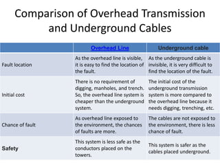
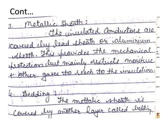
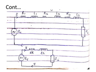
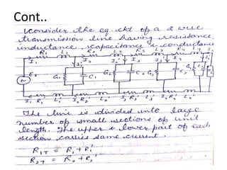
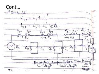
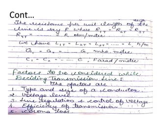
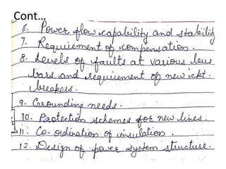
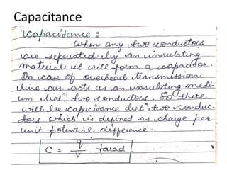
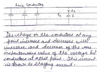
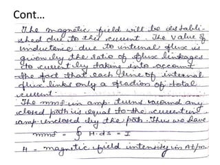
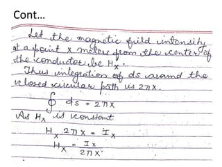
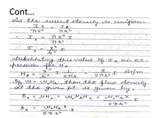
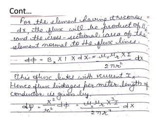
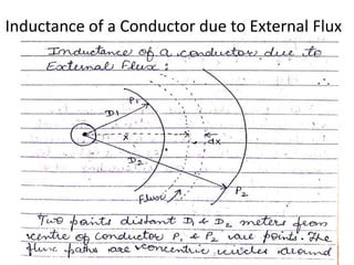
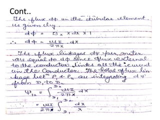
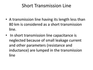
Department of Electrical Engineering
POWER SYSTEM I
UNIT 2
POWER SYSTEM COMPONENTS
From:
Dr. Monika Vardia
Associate Professor
Comparison of Overhead Transmission
and Underground Cables
Overhead Line Underground cable
Fault location
As the overhead line is visible,
it is easy to find the location of
the fault.
As the underground cable is
invisible, it is very difficult to
find the location of the fault.
Initial cost
There is no requirement of
digging, manholes, and trench.
So, the overhead line system is
cheaper than the underground
system.
The initial cost of the
underground transmission
system is more compared to
the overhead line because it
needs digging, trenching, etc.
Chance of fault
As overhead line exposed to
the environment, the chances
of faults are more.
The cables are not exposed to
the environment, there is less
chance of fault.
Safety
This system is less safe as the
conductors placed on the
towers.
This system is safer as the
cables placed underground.
Useful life
In this system, useful life is
approximately 20 to 25 years.
Useful life is approximately 40
to 50 years.
Maintenance cost
In this system, no need to dig
at the time of maintenance.
Hence, for the same number
of faults, the maintenance cost
is less.
In this system, to find the fault,
digging is compulsory. It
increases labor cost. Hence,
for the same number of faults,
the maintenance cost is more.
Flexibility
This system is more flexible.
Because the expansion of the
system is easily possible.
This system is not flexible. The
expansion cost is nearly equal
to the new erection of the
system.
Conductor size
The conductors placed in
atmosphere. So, the heat
dissipation is better. Therefore
the size of the conductor is
small compared to the
underground system.
Because of the poor heat
dissipation, the size of the
cables is more.
Overhead Lines
Conductor Material
Underground Cables
Construction
Cont…
Cont…
Cont…
Parameters of Transmission Lines
Cont…
Cont…
Cont..
Cont…
Cont…
Cont…
Cont..
Cont…
Cont…
Cont…
Cont..
Cont….
Capacitance
Inductance
Cont…
Cont…
Cont…
Cont…
Cont..
Cont…
Inductance of a Conductor due to External Flux
Cont..
Cont..
Cont…
Cont..
Capacitance of Transmission Line
Cont…
Cont….
Potential Difference Between Two
Points Due to a Charge
Cont…
Cont…
Transmission line classification
• Short Transmission Line
• Medium Transmission Line
• Long Transmission Line
Short Transmission Line
• A transmission line having its length less than
80 km is considered as a short transmission
line.
• In short transmission line capacitance is
neglected because of small leakage current
and other parameters (resistance and
inductance) are lumped in the transmission
line
Single and three phase short transmission line
The single phase line is usually short in length and
having low voltage. It has two conductors. Each
conductor has resistance R and inductive reactance X.
Short Transmission Line
• The series impedance of the lines is given as,
Z=R + JX
• In short transmission lines the shunt
conductance and shunt capacitance of the line
are neglected; hence, the current remains the
same at all point of the line.
Practically, we say that,
Phasor Diagram
Short Transmission Line
Power factor of the load measured at the sending end is
Short Transmission Line
For lagging power factor cosΦr, I = I <−Φr = I cosΦr −j IsinΦr
For leading power factor cosΦr, I = I<+Φr = I cosΦr + j IsinΦr
For unity power factor, I = I<0° = I + j0°
The line impedance is given by
Sending end voltage is
If Vr be the reference phasor then,
Short Transmission Line
Medium Transmission Line
• parameters of a medium length transmission line can be represented
using three different models, namely:
• A medium transmission line is defined as a transmission line with an
effective length more than 80 km (50 miles) but less than 250 km (150
miles).
• These lumped
1. Nominal Π representation (nominal pi model)
2. Nominal T representation (nominal T model)
3. End Condenser Method
Nominal Π Representation of a Medium
Transmission Line
• In case of a nominal Π representation (i.e.
nominal pi model), the lumped series impedance
is placed at the middle of the circuit whereas the
shunt admittances are at the ends.
• As we can see from the diagram of the Π network
below, the total lumped shunt admittance is
divided into 2 equal halves, and each half with
value Y ⁄ 2 is placed at both the sending and the
receiving end while the entire circuit impedance
is between the two.
NOMINAL π METHOD
Nominal T Representation of a
Medium Transmission Line
• In the nominal T model of a medium
transmission line the lumped shunt admittance is
placed in the middle, while the net series
impedance is divided into two equal halves and
placed on either side of the shunt admittance.
• The circuit so formed resembles the symbol of a
capital T, and hence is known as the nominal T
network of a medium length transmission line
and is shown in the diagram below.
Cont…
Long Transmission Line
• A transmission line having a length more than 240
km is consider as a long transmission line.
• In a long transmission line, parameters are
uniformly distributed along the whole length of
the line.
• For a long transmission line, it is considered that
the line may be divided into various sections, and
each section consists of an inductance,
capacitance, resistance and conductance
Cont…
Surge Impedance Loading
• Capacitance and reactance are the main
parameters of the transmission line. It is
distributed uniformly along the line. These
parameters are also called distributed
parameters. When the voltage drops occur in
transmission line due to inductance, it is
compensated by the capacitance of the
transmission line.
Cont…
Shunt capacitance charges the transmission line when
the circuit breaker at the sending end of the line is
close.
Cont…
Let V = phase voltage at the receiving end
L = series inductance per phase
XL = series inductance reactance per phase
XC = shunt capacitance reactance per phase
Zo = surge impedance loading per phase
Capacitive volt-amperes (VAr) generated in the
line
Cont…
• Inductive reactive volt-amperes (VAr)
absorbed by the line
And it is calculated by the formula given below
Cont…
• Surge impedance loading is also defined as the
power load in which the total reactive power of
the lines becomes zero.
• The reactive power generated by the shunt
capacitance is consumed by the series inductance
of the line.
• If Po is its natural load of the lines, (SIL)1∅ of the
line per phase
Cont…
• Since the load is purely resistive,
Thus, per phase power transmitted under surge impedance loading is (VP
2)/ZO watts,
Where Vp is the phase voltage.
Cont….
• If kVL is the receiving end voltage in kV, then
Surge impedance loading depends on the voltage of the
transmission line. Practically surge impedance loading
always less than the maximum loading capacity of the line

power system 1 unit 2 ppt (2).pptx

  • 1.
    Department of ElectricalEngineering POWER SYSTEM I UNIT 2 POWER SYSTEM COMPONENTS From: Dr. Monika Vardia Associate Professor
  • 2.
    Comparison of OverheadTransmission and Underground Cables Overhead Line Underground cable Fault location As the overhead line is visible, it is easy to find the location of the fault. As the underground cable is invisible, it is very difficult to find the location of the fault. Initial cost There is no requirement of digging, manholes, and trench. So, the overhead line system is cheaper than the underground system. The initial cost of the underground transmission system is more compared to the overhead line because it needs digging, trenching, etc. Chance of fault As overhead line exposed to the environment, the chances of faults are more. The cables are not exposed to the environment, there is less chance of fault. Safety This system is less safe as the conductors placed on the towers. This system is safer as the cables placed underground.
  • 3.
    Useful life In thissystem, useful life is approximately 20 to 25 years. Useful life is approximately 40 to 50 years. Maintenance cost In this system, no need to dig at the time of maintenance. Hence, for the same number of faults, the maintenance cost is less. In this system, to find the fault, digging is compulsory. It increases labor cost. Hence, for the same number of faults, the maintenance cost is more. Flexibility This system is more flexible. Because the expansion of the system is easily possible. This system is not flexible. The expansion cost is nearly equal to the new erection of the system. Conductor size The conductors placed in atmosphere. So, the heat dissipation is better. Therefore the size of the conductor is small compared to the underground system. Because of the poor heat dissipation, the size of the cables is more.
  • 4.
  • 5.
  • 11.
  • 12.
  • 13.
  • 14.
  • 15.
  • 16.
  • 17.
  • 18.
  • 19.
  • 20.
  • 21.
  • 22.
  • 23.
  • 24.
  • 25.
  • 26.
  • 27.
  • 28.
  • 29.
  • 31.
  • 32.
  • 33.
  • 34.
  • 35.
  • 36.
  • 37.
  • 38.
    Inductance of aConductor due to External Flux
  • 39.
  • 40.
  • 41.
  • 42.
  • 43.
  • 44.
  • 45.
  • 46.
    Potential Difference BetweenTwo Points Due to a Charge
  • 47.
  • 48.
  • 49.
    Transmission line classification •Short Transmission Line • Medium Transmission Line • Long Transmission Line
  • 50.
    Short Transmission Line •A transmission line having its length less than 80 km is considered as a short transmission line. • In short transmission line capacitance is neglected because of small leakage current and other parameters (resistance and inductance) are lumped in the transmission line
  • 51.
    Single and threephase short transmission line The single phase line is usually short in length and having low voltage. It has two conductors. Each conductor has resistance R and inductive reactance X.
  • 52.
    Short Transmission Line •The series impedance of the lines is given as, Z=R + JX • In short transmission lines the shunt conductance and shunt capacitance of the line are neglected; hence, the current remains the same at all point of the line. Practically, we say that,
  • 53.
  • 54.
    Short Transmission Line Powerfactor of the load measured at the sending end is
  • 55.
    Short Transmission Line Forlagging power factor cosΦr, I = I <−Φr = I cosΦr −j IsinΦr For leading power factor cosΦr, I = I<+Φr = I cosΦr + j IsinΦr For unity power factor, I = I<0° = I + j0° The line impedance is given by Sending end voltage is If Vr be the reference phasor then,
  • 56.
  • 57.
    Medium Transmission Line •parameters of a medium length transmission line can be represented using three different models, namely: • A medium transmission line is defined as a transmission line with an effective length more than 80 km (50 miles) but less than 250 km (150 miles). • These lumped 1. Nominal Π representation (nominal pi model) 2. Nominal T representation (nominal T model) 3. End Condenser Method
  • 58.
    Nominal Π Representationof a Medium Transmission Line • In case of a nominal Π representation (i.e. nominal pi model), the lumped series impedance is placed at the middle of the circuit whereas the shunt admittances are at the ends. • As we can see from the diagram of the Π network below, the total lumped shunt admittance is divided into 2 equal halves, and each half with value Y ⁄ 2 is placed at both the sending and the receiving end while the entire circuit impedance is between the two.
  • 59.
  • 60.
    Nominal T Representationof a Medium Transmission Line • In the nominal T model of a medium transmission line the lumped shunt admittance is placed in the middle, while the net series impedance is divided into two equal halves and placed on either side of the shunt admittance. • The circuit so formed resembles the symbol of a capital T, and hence is known as the nominal T network of a medium length transmission line and is shown in the diagram below.
  • 61.
  • 62.
    Long Transmission Line •A transmission line having a length more than 240 km is consider as a long transmission line. • In a long transmission line, parameters are uniformly distributed along the whole length of the line. • For a long transmission line, it is considered that the line may be divided into various sections, and each section consists of an inductance, capacitance, resistance and conductance
  • 63.
  • 64.
    Surge Impedance Loading •Capacitance and reactance are the main parameters of the transmission line. It is distributed uniformly along the line. These parameters are also called distributed parameters. When the voltage drops occur in transmission line due to inductance, it is compensated by the capacitance of the transmission line.
  • 65.
  • 66.
    Shunt capacitance chargesthe transmission line when the circuit breaker at the sending end of the line is close.
  • 67.
    Cont… Let V =phase voltage at the receiving end L = series inductance per phase XL = series inductance reactance per phase XC = shunt capacitance reactance per phase Zo = surge impedance loading per phase Capacitive volt-amperes (VAr) generated in the line
  • 68.
    Cont… • Inductive reactivevolt-amperes (VAr) absorbed by the line And it is calculated by the formula given below
  • 69.
    Cont… • Surge impedanceloading is also defined as the power load in which the total reactive power of the lines becomes zero. • The reactive power generated by the shunt capacitance is consumed by the series inductance of the line. • If Po is its natural load of the lines, (SIL)1∅ of the line per phase
  • 70.
    Cont… • Since theload is purely resistive, Thus, per phase power transmitted under surge impedance loading is (VP 2)/ZO watts, Where Vp is the phase voltage.
  • 71.
    Cont…. • If kVLis the receiving end voltage in kV, then Surge impedance loading depends on the voltage of the transmission line. Practically surge impedance loading always less than the maximum loading capacity of the line