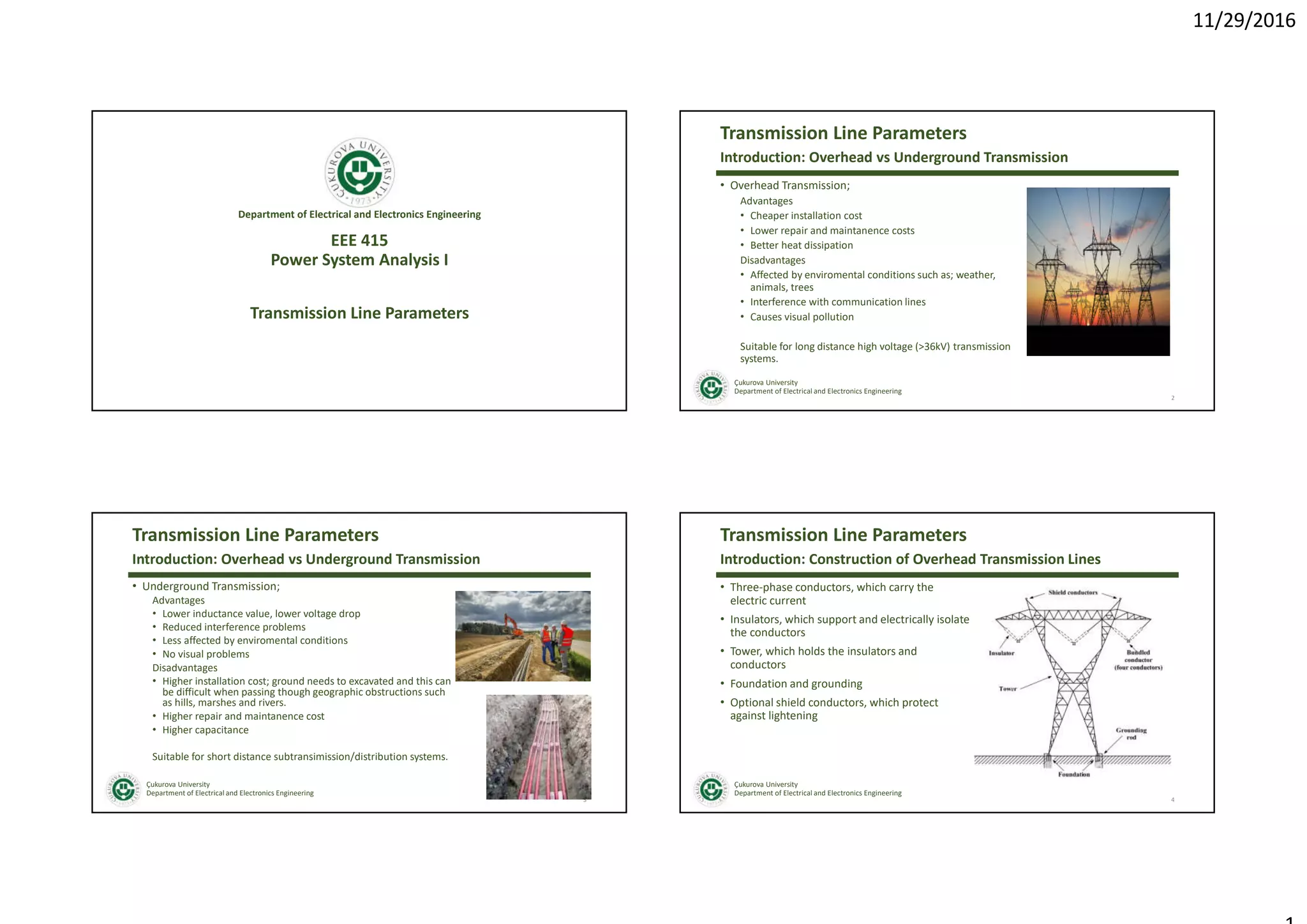
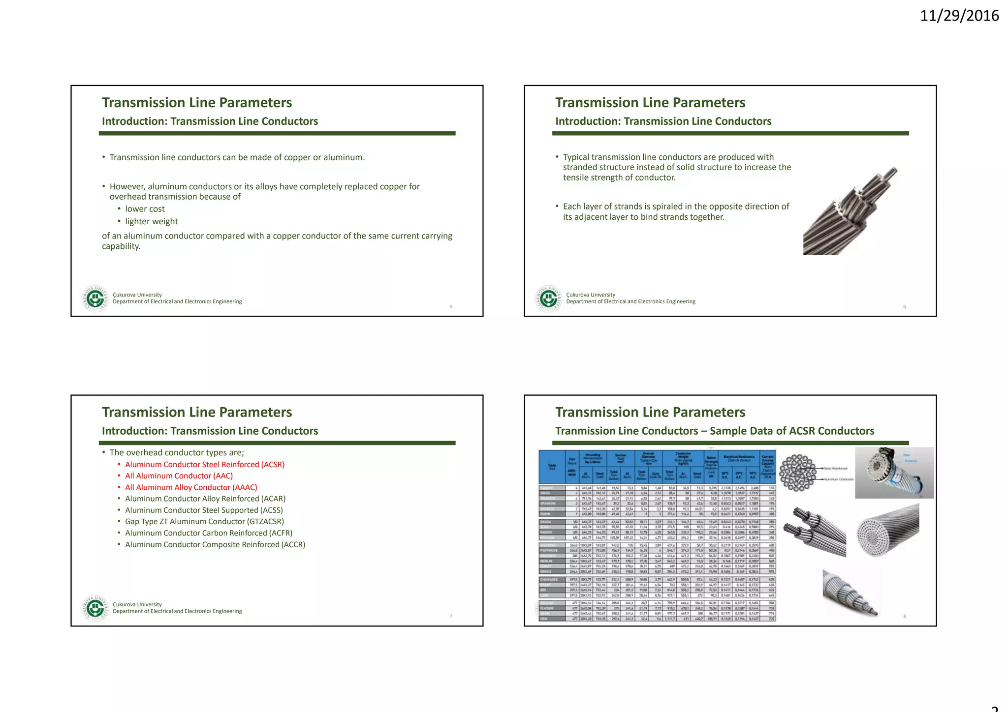
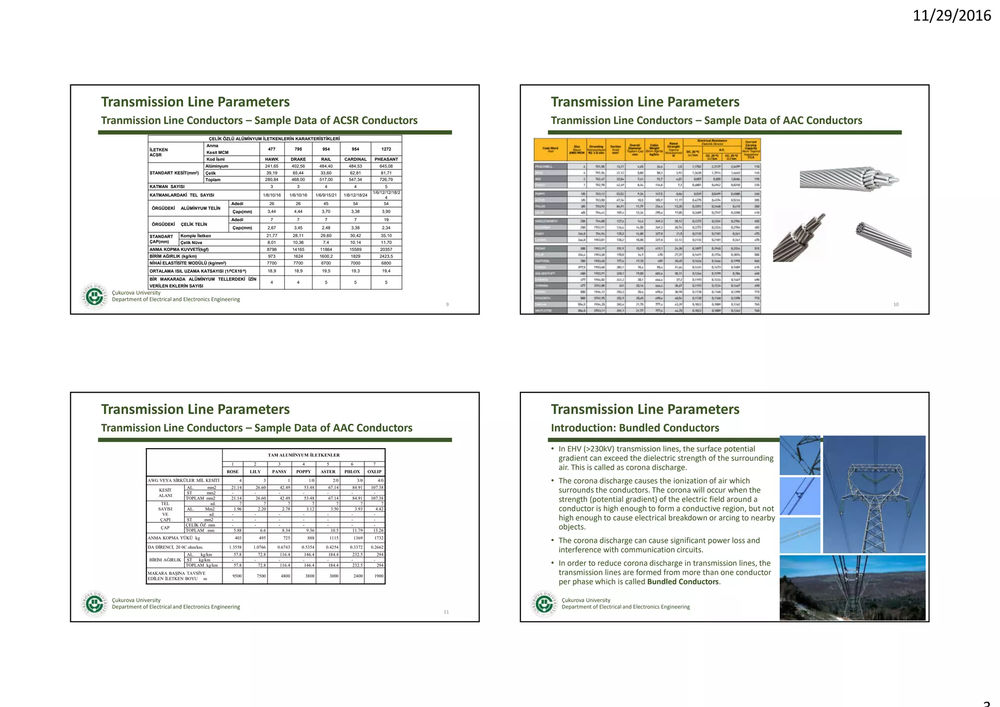
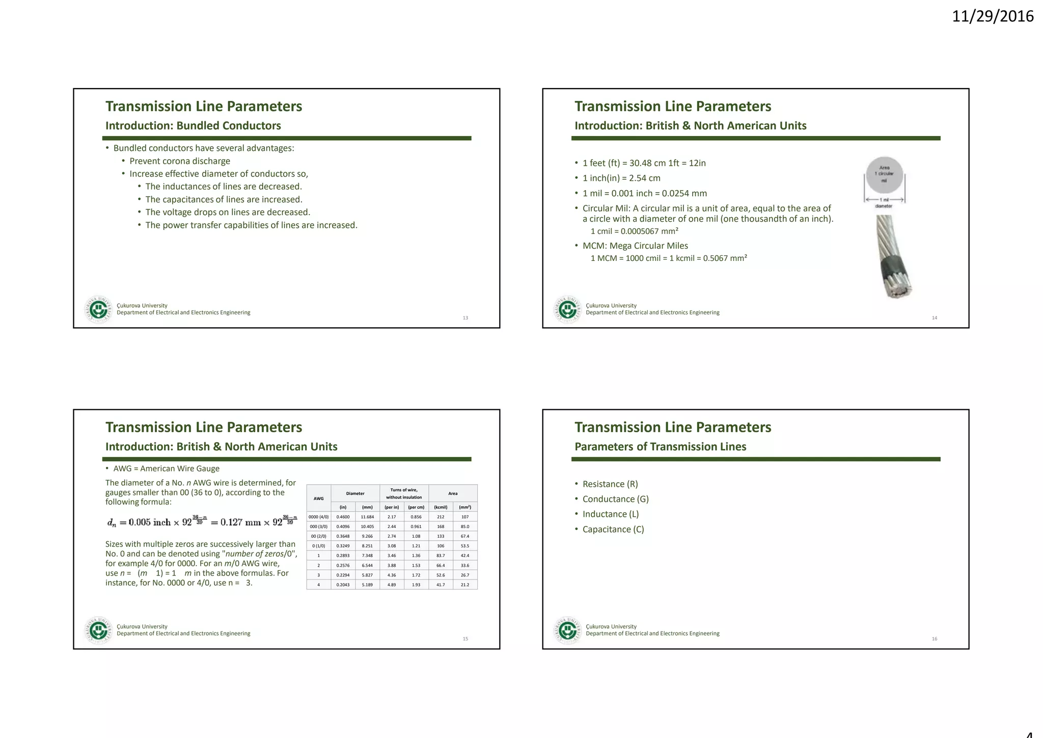
11/29/2016
EEE 415
Power System Analysis I
Department of Electrical and Electronics Engineering
Transmission Line Parameters
Çukurova University
Department of Electrical and Electronics Engineering
Transmission Line Parameters
• Overhead Transmission;
Advantages
• Cheaper installation cost
• Lower repair and maintanence costs
• Better heat dissipation
Disadvantages
• Affected by enviromental conditions such as; weather,
animals, trees
• Interference with communication lines
• Causes visual pollution
Suitable for long distance high voltage (>36kV) transmission
systems.
2
Introduction: Overhead vs Underground Transmission
Çukurova University
Department of Electrical and Electronics Engineering
Transmission Line Parameters
• Underground Transmission;
Advantages
• Lower inductance value, lower voltage drop
• Reduced interference problems
• Less affected by enviromental conditions
• No visual problems
Disadvantages
• Higher installation cost; ground needs to excavated and this can
be difficult when passing though geographic obstructions such
as hills, marshes and rivers.
• Higher repair and maintanence cost
• Higher capacitance
Suitable for short distance subtransimission/distribution systems.
3
Introduction: Overhead vs Underground Transmission
Çukurova University
Department of Electrical and Electronics Engineering
Transmission Line Parameters
• Three-phase conductors, which carry the
electric current
• Insulators, which support and electrically isolate
the conductors
• Tower, which holds the insulators and
conductors
• Foundation and grounding
• Optional shield conductors, which protect
against lightening
4
Introduction: Construction of Overhead Transmission Lines
11/29/2016
Çukurova University
Department of Electrical and Electronics Engineering
Transmission Line Parameters
• Transmission line conductors can be made of copper or aluminum.
• However, aluminum conductors or its alloys have completely replaced copper for
overhead transmission because of
• lower cost
• lighter weight
of an aluminum conductor compared with a copper conductor of the same current carrying
capability.
Introduction: Transmission Line Conductors
5
Çukurova University
Department of Electrical and Electronics Engineering
Transmission Line Parameters
• Typical transmission line conductors are produced with
stranded structure instead of solid structure to increase the
tensile strength of conductor.
• Each layer of strands is spiraled in the opposite direction of
its adjacent layer to bind strands together.
6
Introduction: Transmission Line Conductors
Çukurova University
Department of Electrical and Electronics Engineering
Transmission Line Parameters
• The overhead conductor types are;
• Aluminum Conductor Steel Reinforced (ACSR)
• All Aluminum Conductor (AAC)
• All Aluminum Alloy Conductor (AAAC)
• Aluminum Conductor Alloy Reinforced (ACAR)
• Aluminum Conductor Steel Supported (ACSS)
• Gap Type ZT Aluminum Conductor (GTZACSR)
• Aluminum Conductor Carbon Reinforced (ACFR)
• Aluminum Conductor Composite Reinforced (ACCR)
7
Introduction: Transmission Line Conductors
Çukurova University
Department of Electrical and Electronics Engineering
Transmission Line Parameters
8
Tranmission Line Conductors – Sample Data of ACSR Conductors
11/29/2016
Çukurova University
Department of Electrical and Electronics Engineering
Transmission Line Parameters
9
Tranmission Line Conductors – Sample Data of ACSR Conductors
ÇELİK ÖZLÜ ALÜMİNYUM İLETKENLERİN KARAKTERİSTİKLERİ
İLETKEN
ACSR
Anma
Kesit MCM
477 795 954 954 1272
Kod İsmi HAWK DRAKE RAIL CARDINAL PHEASANT
STANDART KESİT(mm2)
Alüminyum 241,65 402,56 484,40 484,53 645,08
Çelik 39,19 65,44 33,60 62,81 81,71
Toplam 280,84 468,00 517,00 547,34 726,79
KATMAN SAYISI 3 3 4 4 5
KATMANLARDAKİ TEL SAYISI 1/6/10/16 1/6/10/16 1/6/9/15/21 1/6/12/18/24
1/6/12/12/18/2
4
ÖRGÜDEKİ ALÜMİNYUM TELİN
Adedi 26 26 45 54 54
Çapı(mm) 3,44 4,44 3,70 3,38 3,90
ÖRGÜDEKİ ÇELİK TELİN
Adedi 7 7 7 7 19
Çapı(mm) 2,67 3,45 2,48 3,38 2,34
STANDART
ÇAP(mm)
Komple İletken 21,77 28,11 29,60 30,42 35,10
Çelik Nüve 8,01 10,36 7,4 10,14 11,70
ANMA KOPMA KUVVETİ(kgf) 8798 14165 11864 15589 20357
BİRİM AĞIRLIK (kg/km) 973 1624 1600,2 1829 2423,5
NİHAİ ELASTİSİTE MODÜLÜ (kg/mm2) 7700 7700 6700 7000 6800
ORTALAMA ISIL UZAMA KATSAYISI (1/0CX10-6) 18,9 18,9 19,5 19,3 19,4
BİR MAKARADA ALÜMİNYUM TELLERDEKİ İZİN
VERİLEN EKLERİN SAYISI
4 4 5 5 5
Çukurova University
Department of Electrical and Electronics Engineering
Transmission Line Parameters
10
Tranmission Line Conductors – Sample Data of AAC Conductors
Çukurova University
Department of Electrical and Electronics Engineering
Transmission Line Parameters
11
Tranmission Line Conductors – Sample Data of AAC Conductors
TAM ALUMİNYUM İLETKENLER
1 2 3 4 5 6 7
ROSE LILY PANSY POPPY ASTER PHLOX OXLIP
AWG VEYA SİRKÜLER MİL KESİTİ 4 3 1 1/0 2/0 3/0 4/0
KESİT
ALANI
AL. mm2 21.14 26.60 42.49 53.48 67.14 84.91 107.38
ST mm2 - - - - - - -
TOPLAM mm2 21.14 26.60 42.49 53.48 67.14 84.91 107.38
TEL
SAYISI
VE
ÇAPI
ad. 7 7 7 7 7 7 7
AL. Mm2 1.96 2.20 2.78 3.12 3.50 3.93 4.42
ad. - - - - - - -
ST mm2 - - - - - - -
ÇAP
ÇELİK ÖZ mm - - - - - - -
TOPLAM mm 5.88 6.6 8.34 9.36 10.5 11.79 13.26
ANMA KOPMA YÜKÜ kg 403 495 725 888 1115 1369 1732
DA DİRENCİ, 20 0C ohm/km. 1.3558 1.0766 0.6743 0.5354 0.4254 0.3372 0.2662
BİRİM AĞIRLIK
AL. kg/km 57.8 72.8 116.4 146.4 184.4 232.5 294
ST kg/km - - - - - - -
TOPLAM kg/km 57.8 72.8 116.4 146.4 184.4 232.5 294
MAKARA BAŞINA TAVSİYE
EDİLEN İLETKEN BOYU m
9500 7500 4800 3800 3000 2400 1900
Çukurova University
Department of Electrical and Electronics Engineering
Transmission Line Parameters
• In EHV (>230kV) transmission lines, the surface potential
gradient can exceed the dielectric strength of the surrounding
air. This is called as corona discharge.
• The corona discharge causes the ionization of air which
surrounds the conductors. The corona will occur when the
strength (potential gradient) of the electric field around a
conductor is high enough to form a conductive region, but not
high enough to cause electrical breakdown or arcing to nearby
objects.
• The corona discharge can cause significant power loss and
interference with communication circuits.
• In order to reduce corona discharge in transmission lines, the
transmission lines are formed from more than one conductor
per phase which is called Bundled Conductors.
12
Introduction: Bundled Conductors
11/29/2016
Çukurova University
Department of Electrical and Electronics Engineering
Transmission Line Parameters
• Bundled conductors have several advantages:
• Prevent corona discharge
• Increase effective diameter of conductors so,
• The inductances of lines are decreased.
• The capacitances of lines are increased.
• The voltage drops on lines are decreased.
• The power transfer capabilities of lines are increased.
13
Introduction: Bundled Conductors
Çukurova University
Department of Electrical and Electronics Engineering
Transmission Line Parameters
• 1 feet (ft) = 30.48 cm 1ft = 12in
• 1 inch(in) = 2.54 cm
• 1 mil = 0.001 inch = 0.0254 mm
• Circular Mil: A circular mil is a unit of area, equal to the area of
a circle with a diameter of one mil (one thousandth of an inch).
1 cmil = 0.0005067 mm²
• MCM: Mega Circular Miles
1 MCM = 1000 cmil = 1 kcmil = 0.5067 mm²
14
Introduction: British & North American Units
Çukurova University
Department of Electrical and Electronics Engineering
Transmission Line Parameters
• AWG = American Wire Gauge
The diameter of a No. n AWG wire is determined, for
gauges smaller than 00 (36 to 0), according to the
following formula:
Sizes with multiple zeros are successively larger than
No. 0 and can be denoted using "number of zeros/0",
for example 4/0 for 0000. For an m/0 AWG wire,
use n = (m 1) = 1 m in the above formulas. For
instance, for No. 0000 or 4/0, use n = 3.
15
Introduction: British & North American Units
AWG
Diameter
Turns of wire,
without insulation
Area
(in) (mm) (per in) (per cm) (kcmil) (mm2)
0000 (4/0) 0.4600 11.684 2.17 0.856 212 107
000 (3/0) 0.4096 10.405 2.44 0.961 168 85.0
00 (2/0) 0.3648 9.266 2.74 1.08 133 67.4
0 (1/0) 0.3249 8.251 3.08 1.21 106 53.5
1 0.2893 7.348 3.46 1.36 83.7 42.4
2 0.2576 6.544 3.88 1.53 66.4 33.6
3 0.2294 5.827 4.36 1.72 52.6 26.7
4 0.2043 5.189 4.89 1.93 41.7 21.2
Çukurova University
Department of Electrical and Electronics Engineering
Transmission Line Parameters
• Resistance (R)
• Conductance (G)
• Inductance (L)
• Capacitance (C)
16
Parameters of Transmission Lines
11/29/2016
Çukurova University
Department of Electrical and Electronics Engineering
Transmission Line Parameters
• The dc resistance of a conductor at a specified temperature T is
where
ρT = conductor resistivity at temperature T
l = conductor length
A = conductor cross-sectional area
17
Resistance
Çukurova University
Department of Electrical and Electronics Engineering
Transmission Line Parameters
• Conductor resistance depends on the following factors:
• Spiraling
• Temperature
• Frequency – Skin Effect
18
Resistance
Çukurova University
Department of Electrical and Electronics Engineering
Transmission Line Parameters
• Spiraling
• For stranded conductors, alternate layers of strands are spiraled in opposite directions to
hold the strands together.
• Spiraling makes the strands 1 or 2% longer than the actual conductor length.
• As a result, the dc resistance of a stranded conductor is 1 or 2% larger than that calculated
value for a specified conductor length.
19
Resistance
Çukurova University
Department of Electrical and Electronics Engineering
Transmission Line Parameters
• Temperature
• Resistivity of conductor metals varies linearly over
normal operating temperatures according to
where ρT1 and ρT2 are resistivities at temperatures T1
and T2°C, respectively. T is a temperature constant
that depends on the conductor material.
20
Resistance
11/29/2016
Çukurova University
Department of Electrical and Electronics Engineering
Transmission Line Parameters
• Temperature
21
Resistance
Çukurova University
Department of Electrical and Electronics Engineering
Transmission Line Parameters
• Frequency – Skin Effect
• For dc, the current distribution is uniform throughout the conductor cross section.
However, for ac, the current distribution is non-uniform. As frequency increases, the
current in a solid cylindrical conductor tends to crowd toward the conductor surface,
with smaller current density at the conductor center. This phenomenon is called skin
effect.
• The skin effect causes the decrease of effective area of conductors. Thus, the ac
resistance of conductor is higher than the dc resistance.
22
Resistance
Çukurova University
Department of Electrical and Electronics Engineering
Transmission Line Parameters
• The ac resistance or effective resistance of a conductor can be calculated using,
where Ploss is the conductor real power loss in watts and I is the rms conductor current.
• Wire manufacturers usually supply tables of resistance per unit length at common
frequencies (50 or 60 Hz) and different temperatures. Therefore, the resistance can be
determined from such tables.
23
Resistance
Çukurova University
Department of Electrical and Electronics Engineering
Transmission Line Parameters
• Conductance accounts for real power loss between conductors or between conductors
and ground. For overhead lines, this power loss is due to leakage currents at insulators
and to corona.
• Insulator leakage current depends on the amount of dirt, salt, and other contaminants
that have accumulated on insulators, as well as on meteorological factors, particularly
the presence of moisture.
• Corona occurs when a high value of electric field strength at a conductor surface causes
the air to become electrically ionized and to conduct. The real power loss due to corona,
called corona loss, depends on meteorological conditions, particularly rain, and on
conductor surface irregularities.
• Losses due to insulator leakage and corona are usually small compared to conductor I2R
loss. Conductance is usually neglected in power system studies because it is a very small
component of the shunt admittance.
24
Conductance
11/29/2016
Çukurova University
Department of Electrical and Electronics Engineering
Transmission Line Parameters
• The inductance of a magnetic circuit that has a constant permeability µ can be obtained
by determining the following:
1. Magnetic field intensity H, from Ampere’s law.
2. Magnetic flux density B. ( B = µH )
3. Flux linkages λ.
4. Inductance from flux linkages per ampere ( L = λI )
25
Inductance: Solid Cylindrical Conductor
Çukurova University
Department of Electrical and Electronics Engineering
Transmission Line Parameters
Internal Inductance (Self Inductance)
For simplicity, assume that the conductor;
(1) is sufficiently long that end effects are neglected.
(2) is nonmagnetic (µ = µ0 = 4π x 10-7 H/m).
(3) has a uniform current density (skin effect is neglected).
26
Inductance: Solid Cylindrical Conductor
Çukurova University
Department of Electrical and Electronics Engineering
Transmission Line Parameters
Internal Inductance (Self Inductance)
• From Ampere’s law;
• To determine the magnetic field inside the conductor,
select the dashed circle of radius x < r.
where Ix is the portion of the total current enclosed by
the contour.
27
Inductance: Solid Cylindrical Conductor
Çukurova University
Department of Electrical and Electronics Engineering
Transmission Line Parameters
Internal Inductance (Self Inductance)
• Assume that a uniform current distribution within the
conductor, the current enclosed by the conductor is equal to;
• The magnetic field inside the conductor becomes;
• For a nonmagnetic conductor, the magnetic flux density Bx is
28
Inductance: Solid Cylindrical Conductor
11/29/2016
Çukurova University
Department of Electrical and Electronics Engineering
Transmission Line Parameters
Internal Inductance
• The differential flux dφ per-unit length of conductor in
the cross-hatched rectangle of width dx is;
• Since only the fraction (x/r)2 of the total current I is
linked by the flux, the computation of the differential
flux linkage dλ in the rectangle is
29
Inductance: Solid Cylindrical Conductor
Çukurova University
Department of Electrical and Electronics Engineering
Transmission Line Parameters
Internal Inductance
• λint inside the conductor is determined by integrating dλ
from x=0 to x=r as;
• The internal inductance Lint per-unit length of conductor
due to this flux linkage is;
30
Inductance: Solid Cylindrical Conductor
Çukurova University
Department of Electrical and Electronics Engineering
Transmission Line Parameters
External Inductance
• To determine the magnetic field outside the conductor,
select the dashed circle of radius x > r as the closed
contour for Ampere’s law.
• In this condition, this contour encloses the entire
current I so,
31
Inductance: Solid Cylindrical Conductor
Çukurova University
Department of Electrical and Electronics Engineering
Transmission Line Parameters
External Inductance
• Outside the conductor, µ = µ0 so,
• Since the entire current I is linked by the flux outside
the conductor,
32
Inductance: Solid Cylindrical Conductor
11/29/2016
Çukurova University
Department of Electrical and Electronics Engineering
Transmission Line Parameters
External Inductance
• Integrating dλ between two external points at distances
D1 and D2 from the conductor center gives the external
flux linkage λ12 between D1 and D2:
• The external inductance L12 per-unit length due to the
flux linkages between D1 and D2 is then
33
Inductance: Solid Cylindrical Conductor
Çukurova University
Department of Electrical and Electronics Engineering
Transmission Line Parameters
Total Inductance
• The total flux λP linking the conductor out to external point P at distance D is the sum of
the internal flux linkage and the external flux linkage from D1 = r to D2 = D as,
• Using the identity ½ = 2ln e1/4 a more convenient expression for λP is obtained:
34
Inductance: Solid Cylindrical Conductor
Çukurova University
Department of Electrical and Electronics Engineering
Transmission Line Parameters
Total Inductance
• The total inductance LP due to both internal and external flux linkages out to distance D
is;
35
Inductance: Solid Cylindrical Conductor
Çukurova University
Department of Electrical and Electronics Engineering
Transmission Line Parameters
The Array of Solid Cylindrical Conductors
• Assume that each conductor m carries current Im and
the sum of the conductor currents is zero as,
• The flux linkage λkPk which links conductor k out to
point P due to current λk is,
• λkPk includes both internal and external flux linkages
due to Ik.
36
Inductance: Solid Cylindrical Conductor
11/29/2016
Çukurova University
Department of Electrical and Electronics Engineering
Transmission Line Parameters
The Array of Solid Cylindrical Conductors
• The flux linkage λkPm, which links conductor k out to P
due to Im is,
Dkm>>rk
Dkm ≈ (Dkm – rk) ≈ (Dkm + rk)
37
Inductance: Solid Cylindrical Conductor
Çukurova University
Department of Electrical and Electronics Engineering
Transmission Line Parameters
The Array of Solid Cylindrical Conductors
• Using superposition, the total flux linkage λkP, which
links conductor k out to P due to all the currents is,
where we define Dkk = r’k = e-1/4rk when m = k in the
above summation.
38
Inductance: Solid Cylindrical Conductor
Çukurova University
Department of Electrical and Electronics Engineering
Transmission Line Parameters
The Array of Solid Cylindrical Conductors
• The above equation can be separated into two
summations as;
• Removing the last term from the second summation
we can get;
39
Inductance: Solid Cylindrical Conductor
Çukurova University
Department of Electrical and Electronics Engineering
Transmission Line Parameters
The Array of Solid Cylindrical Conductors
40
Inductance: Solid Cylindrical Conductor
11/29/2016
Çukurova University
Department of Electrical and Electronics Engineering
Transmission Line Parameters
The Array of Solid Cylindrical Conductors
• When P  ∞, all the distances DPm become equal, the
ratios DPm=DPM become unity, and ln(DPm /DPM) 0.
• The total flux linking conductor k out to infinity λk is
equal to;
41
Inductance: Solid Cylindrical Conductor
Çukurova University
Department of Electrical and Electronics Engineering
Transmission Line Parameters
• Conductor x with radius rx carries phasor current Ix = I
referenced out of the page.
• Conductor y with radius ry carries return current Iy = -I.
• The sum of the two currents is zero.
42
Inductance: Single Phase Two Wire Line
Çukurova University
Department of Electrical and Electronics Engineering
Transmission Line Parameters
• The total flux linking conductor x is;
where
• The inductance of conductor x is;
43
Inductance: Single Phase Two Wire Line
Çukurova University
Department of Electrical and Electronics Engineering
Transmission Line Parameters
• Similarly, the total flux linking conductor y is
• The inductance of conductor y is;
44
Inductance: Single Phase Two Wire Line
11/29/2016
Çukurova University
Department of Electrical and Electronics Engineering
Transmission Line Parameters
• The total inductance of the single-phase circuit, also called
loop inductance, is;
if r’x = r’y = r’, the total circuit inductance is
45
Inductance: Single Phase Two Wire Line
Çukurova University
Department of Electrical and Electronics Engineering
Transmission Line Parameters
• The composite conductors consist of two or more solid
cylindrical subconductors in parallel.
• A stranded conductor is one example of a composite
conductor.
• For simplicity of calculations, it is assumed that the
subconductors are identical and share the conductor
current equally for each conductor.
46
Inductance: Composite Conductors and Unequal Spacing
Çukurova University
Department of Electrical and Electronics Engineering
Transmission Line Parameters
• A single-phase two-conductor line consisting of two
composite conductors x and y.
• Conductor x has N identical subconductors, each with
radius rx and with current (I/N) referenced out of the
page.
• Similarly, conductor y consists of M identical
subconductors, each with radius ry and with return
current (-I/M).
47
Inductance: Composite Conductors and Unequal Spacing
Çukurova University
Department of Electrical and Electronics Engineering
Transmission Line Parameters
• Since the sum of all the currents is zero, the total flux
φk linking subconductor k of conductor x is;
• Since only the fraction (1 /N) of the total conductor
current I is linked by this flux, the flux linkage λk of (the
current in) subconductor k is
48
Inductance: Composite Conductors and Unequal Spacing
11/29/2016
Çukurova University
Department of Electrical and Electronics Engineering
Transmission Line Parameters
• The total flux linkage of conductor x is
• Using and
• The total flux linkage of conductor x can reorginized as;
49
Inductance: Composite Conductors and Unequal Spacing
Çukurova University
Department of Electrical and Electronics Engineering
Transmission Line Parameters
• The total flux linkage of conductor x is
where
50
Inductance: Composite Conductors and Unequal Spacing
Çukurova University
Department of Electrical and Electronics Engineering
Transmission Line Parameters
• Dxy is called the geometric mean distance or GMD
between conductors x and y.
• Dxx is called the geometric mean radius or GMR of
conductor x.
• Similarly, for conductor y,
• Dyy, the GMR of conductor y, is
• The total inductance L of the single-phase circuit is
51
Inductance: Composite Conductors and Unequal Spacing
Çukurova University
Department of Electrical and Electronics Engineering
Transmission Line Parameters
• It is seldom necessary to calculate GMR or GMD for standard lines.
• The GMR of standard conductors is provided by conductor manufacturers and can be
found in various handbooks.
• Also, if the distances between conductors are large compared to the distances between
subconductors of each conductor, then the GMD between conductors is approximately
equal to the distance between conductor centers.
52
Inductance: Composite Conductors and Unequal Spacing
11/29/2016
Çukurova University
Department of Electrical and Electronics Engineering
Transmission Line Parameters
• Example 1:
Evaluate the inductance of conductor x, conductor y and the total inductance in H/m for
the single-phase two-conductor line shown in Figure.
53
Inductance: Composite Conductors and Unequal Spacing
Çukurova University
Department of Electrical and Electronics Engineering
Transmission Line Parameters
• Example 2:
A single-phase line operating at 60 Hz consists of two 4/0 12-strand copper conductors
with 1.5 m spacing between conductor centers. The line length is 32 km. Determine the
total inductance in H and the total inductive reactance in W.
The GMR of a 4/0 12-strand copper conductor is Dxx=Dyy=0.01750 ft or 0.5334 cm.
54
Inductance: Composite Conductors and Unequal Spacing
Çukurova University
Department of Electrical and Electronics Engineering
Transmission Line Parameters
• A three-phase three-wire line consists of three solid cylindrical
conductors a, b, c, each with radius r, and with equal phase
spacing D between any two conductors.
• To determine inductance, assume balanced positive-sequence
currents Ia, Ib, Ic that satisfy;
55
Inductance: 3 Phase 3 Wire Line with Equal Phase Spacing
Çukurova University
Department of Electrical and Electronics Engineering
Transmission Line Parameters
• The total flux linking the phase a conductor is equal to;
• Using
56
Inductance: 3 Phase 3 Wire Line with Equal Phase Spacing
11/29/2016
Çukurova University
Department of Electrical and Electronics Engineering
Transmission Line Parameters
• The inductance of phase a is;
• Due to symmetry, the same result is obtained for Lb = λb /Ib and
for Lc = λc /Ic.
• However, only one phase need be considered for balanced three
phase operation of this line, since the flux linkages of each
phase have equal magnitudes and 120° displacement.
57
Inductance: 3 Phase 3 Wire Line with Equal Phase Spacing
Çukurova University
Department of Electrical and Electronics Engineering
Transmission Line Parameters
• To calculate inductance for three-phase lines with
stranded conductors and equal phase spacing, r’ is
replaced by the conductor GMR in;
• If the spacings between phases are unequal, then
balanced positive-sequence flux linkages are not
obtained from balanced positive-sequence
currents. Instead, unbalanced flux linkages occur,
and the phase inductances are unequal.
58
Inductance: Transposition
Çukurova University
Department of Electrical and Electronics Engineering
Transmission Line Parameters
59
Inductance: Transposition
Çukurova University
Department of Electrical and Electronics Engineering
Transmission Line Parameters
• For balanced three phase system, currents can be
represented with taking Ia as reference;
where
60
Inductance: Transposition
11/29/2016
Çukurova University
Department of Electrical and Electronics Engineering
Transmission Line Parameters
• If the spacings between phases are unequal, the phase inductances are not equal
(unbalanced) and contain an imaginary term due to the mutual inductance.
• In order to balance the inductance of phase conductors, the conductor positions can be
exchanged along the line.
• This technique is called as transposition.
• A completely transposed three-phase line is transposed at two locations such that each
phase occupies each position for one-third of the line length.
61
Inductance: Transposition
Çukurova University
Department of Electrical and Electronics Engineering
Transmission Line Parameters
• The line shown in figure is transposed at two
locations such that each phase occupies each
position for one-third of the line length. Conductor
positions are denoted 1, 2, 3 with distances D12,
D23, D31 between positions.
• The conductors are identical, each with GMR
denoted DS.
62
Inductance: Transposition
Çukurova University
Department of Electrical and Electronics Engineering
Transmission Line Parameters
• To calculate inductance of this line, assume
balanced positive-sequence currents Ia, Ib and Ic for
which Ia+Ib+Ic=0.
• The total flux linkinges of the phase a conductor
while it is in position 1, 2 and 3 are;
63
Inductance: Transposition
Çukurova University
Department of Electrical and Electronics Engineering
Transmission Line Parameters
• The average of the flux linkages is
• Using (Ib+Ic)=-Ia,
64
Inductance: Transposition
11/29/2016
Çukurova University
Department of Electrical and Electronics Engineering
Transmission Line Parameters
• The average inductance of phase a is
• Same result can be obtained for Lb and Lc. However,
only one phase need be considered for balanced
three-phase operation of a completely transposed
three-phase line.
65
Inductance: Transposition
Çukurova University
Department of Electrical and Electronics Engineering
Transmission Line Parameters
• Deq, the cube root of the product of the three-phase
spacings, is the geometric mean distance between
phases.
• DS is the conductor GMR for stranded conductors,
or r’ for solid cylindrical conductors.
66
Inductance: Transposition
Çukurova University
Department of Electrical and Electronics Engineering
Transmission Line Parameters
• Example 3
A completely transposed 60-Hz three-phase line has flat horizontal phase spacing with 10
m between adjacent conductors. The conductors are 806 mm2 (1,590,000 cmil) ACSR with
54/3 stranding. Line length is 200 km. Determine the inductance in H and the inductive
reactance in Ω. The GMR of a 806 mm2 (1,590,000 cmil) 54/3 ACSR conductor is 0.0159 m
(0.052 ft).
67
Inductance: Transposition
Çukurova University
Department of Electrical and Electronics Engineering
Transmission Line Parameters
• Figure shows common EHV bundles consisting of two, three, or four
conductors.
• To calculate inductance in bundled conductors, DS is replaced by the GMR of
the bundle. Since the bundle constitutes a composite conductor, calculation
of bundle GMR is given by;
68
Inductance: Bundled Conductors
11/29/2016
Çukurova University
Department of Electrical and Electronics Engineering
Transmission Line Parameters
• If the conductors are stranded and the bundle spacing d is large compared to
the conductor outside radius, each stranded conductor is first replaced by an
equivalent solid cylindrical conductor with GMR=DS. Then the bundle is
replaced by one equivalent conductor with GMR=DSL which is calculated for
n=2, 3, 4 … as follows:
69
Inductance: Bundled Conductors
Çukurova University
Department of Electrical and Electronics Engineering
Transmission Line Parameters
• The inductance is calculated for bundled conductors as;
• If the phase spacings are large compared to the bundle spacing, then
sufficient accuracy for Deq is obtained by using the distances between bundle
centers.
70
Inductance: Bundled Conductors
Çukurova University
Department of Electrical and Electronics Engineering
Transmission Line Parameters
• Example 4:
Each of the 806 mm2 conductors in Example 3 is replaced by two 403 mm2 ACSR 26/2
conductors, as shown in Figure. Bundle spacing is 0.40 m. Flat horizontal spacing is
retained, with 10 m between adjacent bundle centers. Calculate the inductive reactance of
the line and compare it with that of Example 3.
71
Inductance: Bundled Conductors
Çukurova University
Department of Electrical and Electronics Engineering
Transmission Line Parameters
• A three phase double circuit line consists of two
identical three phase circuits.
• Double circuits are used where greater reliability
is needed.
• This method of transmission enables the transfer
of more power over a particular distance.
72
Inductance: Double Circuit Three Phase Lines
11/29/2016
Çukurova University
Department of Electrical and Electronics Engineering
Transmission Line Parameters
• The circuits are operated with a1-a2, b1-b2 and c1-c2 in
parallel.
• Because of the geometrical differences between
conductors, voltage drop due to line inductance will be
unbalanced.
• To achieve balance operation, each phase conductor must
be transposed within its group and with respect to the
parallel three phase line.
73
Inductance: Double Circuit Three Phase Lines
a1
b1
c1
c2
b2
a2
Çukurova University
Department of Electrical and Electronics Engineering
Transmission Line Parameters
The arrangement of conductors of a transposed double circuit line:
74
Inductance: Double Circuit Three Phase Lines
a1
b1
c1
c2
b2
a2
SECTION 1
c1
a1
b1
b2
a2
c2
SECTION 2
b1
c1
a1
a2
c2
b2
SECTION 3
Çukurova University
Department of Electrical and Electronics Engineering
Transmission Line Parameters
• By grouping the identical phases together, GMD between
each phase group can be found as;
75
Inductance: Double Circuit Three Phase Lines
• The equivalent GMD per phase is equal to;
a1
b1
c1
c2
b2
a2
Çukurova University
Department of Electrical and Electronics Engineering
Transmission Line Parameters
• The GMR of each phase group is
76
Inductance: Double Circuit Three Phase Lines
where is the geometric mean radius of the bundled
conductors.
• The equivalent GMR for calculating the per-phase
inductance is equal to;
a1
b1
c1
c2
b2
a2
11/29/2016
Çukurova University
Department of Electrical and Electronics Engineering
Transmission Line Parameters
• The inductance per phase in millihenries per kilometer is
equal to;
77
Inductance: Double Circuit Three Phase Lines
a1
b1
c1
c2
b2
a2
Çukurova University
Department of Electrical and Electronics Engineering
Transmission Line Parameters
• The capacitance between conductors in a medium with constant permittivity ε can be
obtained by determining the following:
1. Electric field strength E, from Gauss’s law
2. Voltage between conductors
3. Capacitance from charge per unit volt (C = q/V)
78
Capacitance
Çukurova University
Department of Electrical and Electronics Engineering
Transmission Line Parameters
• Figure shows a solid cylindrical conductor with radius r and
with positive charge q coloumbs per meter uniformly
distributed on the conductor surface.
• For simplicity, assume that the conductor is,
• sufficiently long that end effects are negligible.
• a perfect conductor (that is, zero resistivity, ρ=0).
79
Capacitance: Solid Cylindrical Conductor
Çukurova University
Department of Electrical and Electronics Engineering
Transmission Line Parameters
Internal Electric Field
• Inside the perfect conductor, Ohm’s law gives Eint= ρJ=0. That
is, the internal electric field Eint is zero.
80
Capacitance: Solid Cylindrical Conductor
11/29/2016
Çukurova University
Department of Electrical and Electronics Engineering
Transmission Line Parameters
External Electric Field
• To determine the electric field outside the conductor, select
the cylinder with radius r and with 1-meter length.
• Due to the uniform charge distribution, the electric field
strength Ex is constant on the cylinder. Also, there is no
tangential component of Ex, so the electric field is
radial to the conductor. Then the electric field strength Ex is
equal to;
where ε= ε0=8.854x10⁻¹²F/m for a conductor in free space.
81
Capacitance: Solid Cylindrical Conductor
Çukurova University
Department of Electrical and Electronics Engineering
Transmission Line Parameters
External Electric Field
• Concentric cylinders surrounding the conductor are constant
potential surfaces. The potential difference between two
concentric cylinders at distances D1 and D2 from the conductor
center is,
82
Capacitance: Solid Cylindrical Conductor
Çukurova University
Department of Electrical and Electronics Engineering
Transmission Line Parameters
The Array of Solid Cylindrical Conductors
• Assume that each conductor m has an ac charge qm C/m
uniformly distributed along the conductor. The voltage Vkim
between conductors k and i due to the charge qm acting
alone is
where Dmm = rm when k = m or i = m.
• The distortion of the electric field in the vicinity of the other
conductors is neglected.
83
Capacitance: Solid Cylindrical Conductor
Çukurova University
Department of Electrical and Electronics Engineering
Transmission Line Parameters
The Array of Solid Cylindrical Conductors
• Using superposition, the voltage Vki between conductors k
and i due to all the charges is
84
Capacitance: Solid Cylindrical Conductor
11/29/2016
Çukurova University
Department of Electrical and Electronics Engineering
Transmission Line Parameters
• Assume that the conductors are energized by a voltage source
such that conductor x has a uniform charge q C/m and,
assuming conservation of charge, conductor y has an equal
quantity of negative charge -q.
• Potential difference between conductor x and conductor y is;
• Using Dxy=Dyx=D, Dxx=rx, and Dyy=ry,
85
Capacitance: Single Phase Two Wire Line
Çukurova University
Department of Electrical and Electronics Engineering
Transmission Line Parameters
• For a 1-meter line length, the capacitance between conductors is
• If rx=ry=r,
86
Capacitance: Single Phase Two Wire Line
Çukurova University
Department of Electrical and Electronics Engineering
Transmission Line Parameters
• If the two-wire line is supplied by a transformer with a grounded
center tap, then the voltage between each conductor and
ground is one-half
• The capacitance from either line to the grounded neutral is
87
Capacitance: Single Phase Two Wire Line
Çukurova University
Department of Electrical and Electronics Engineering
Transmission Line Parameters
• Practical conductors have a small internal electric field because of their resistivities. As a
result, the external electric field is slightly altered near the conductor surfaces.
• In addition, the electric field near the surface of a stranded conductor is not the same as
that of a solid cylindrical conductor. However , it is normal practice when calculating line
capacitance to replace a stranded conductor by a perfectly conducting solid cylindrical
conductor whose radius equals the outside radius of the stranded conductor. The
resulting error in capacitance is small since only the electric field near the conductor
surfaces is affected.
88
Capacitance: Composite Conductors and Unequal Spacing
11/29/2016
Çukurova University
Department of Electrical and Electronics Engineering
Transmission Line Parameters
• In order to determine the positive-sequence capacitance, the effect of
earth and neutral conductors is neglected and the positive-sequence
charges qa, qb, qc are assumed such that qa+qb+qc=0. the voltage Vab
between conductors a and b is
• Using Daa=Dbb=r, and Dab=Dba=Dca=Dcb=D, the voltage Vab becomes
89
Capacitance: 3 Phase 3 Wire Line with Equal Phase Spacing
• Note that the third term in the equation of Vab is zero because
conductors a and b are equidistant from conductor c. Thus,
conductors a and b lie on a constant potential cylinder for the
electric field due to qc.
Çukurova University
Department of Electrical and Electronics Engineering
Transmission Line Parameters
• Similarly, the voltage Vac between conductors a and c is
90
Capacitance: 3 Phase 3 Wire Line with Equal Phase Spacing
Çukurova University
Department of Electrical and Electronics Engineering
Transmission Line Parameters
• Recall that for balanced positive-sequence voltages,
• With using balanced positive-sequence voltage equations, the
voltage Van between conductors a and neutral becomes;
91
Capacitance: 3 Phase 3 Wire Line with Equal Phase Spacing
Çukurova University
Department of Electrical and Electronics Engineering
Transmission Line Parameters
• Using qb+qc=-qa for the three phase balance situation, Van becomes;
• The capacitance-to-neutral per line length is
• Due to symmetry, the same result is obtained for Cbn=qb/Vbn and
Ccn=qc/Vcn. For balanced three-phase operation, however, only one
phase need be considered.
92
Capacitance: 3 Phase 3 Wire Line with Equal Phase Spacing
11/29/2016
Çukurova University
Department of Electrical and Electronics Engineering
Transmission Line Parameters
• For three-phase lines with unequal phase spacing, balanced positive sequence voltages
are not obtained with balanced positive-sequence charges.
• Instead, unbalanced line-to-neutral voltages occur, and the phase- to-neutral
capacitances are unequal. Balance can be restored by transposing the line such that each
phase occupies each position for one-third of the line length.
93
Capacitance: Unequal Phase Spacing
Çukurova University
Department of Electrical and Electronics Engineering
Transmission Line Parameters
• If the equations of Vab and Vac are written for each position in the transposition cycle, and
are then averaged, the resulting capacitance becomes;
94
Capacitance: Transposition
Çukurova University
Department of Electrical and Electronics Engineering
Transmission Line Parameters
• Figure shows a bundled conductor line with two
conductors per bundle.
• To determine the capacitance of this line, assume
balanced positive sequence charges qa, qb, qc for each
phase such that qa+qb+qc=0.
• Assume that the conductors in each bundle, which are in
parallel, share the charges equally. Thus conductors a and
a’ each have the charge qa/2.
• Also assume that the phase spacings are much larger than
the bundle spacings so that Dab may be used instead of
(Dab-d) or (Dab+d).
95
Capacitance: Bundled Conductors
Çukurova University
Department of Electrical and Electronics Engineering
Transmission Line Parameters
• The voltage between conductors a and b, Vab is equal to;
96
Capacitance: Bundled Conductors
11/29/2016
Çukurova University
Department of Electrical and Electronics Engineering
Transmission Line Parameters
• For a transposed line, derivation of the capacitance would
yield;
97
Capacitance: Bundled Conductors
Çukurova University
Department of Electrical and Electronics Engineering
Transmission Line Parameters
• The capacitance equation is analogous to the inductance equation.
• In both inductance and capacitance equations, Deq is the geometric mean
of the distances between phases.
• Also, DSC in the capacitance equations is analogous to DSL in the inductance
equations, except that the conductor outside radius r replaces the
conductor GMR DS.
98
Capacitance: Bundled Conductors
Çukurova University
Department of Electrical and Electronics Engineering
Transmission Line Parameters
• Example 5
A single-phase line operating at 60 Hz consists of two 4/0 12-strand copper conductors
with 1.5 m spacing between conductor centers. The line length is 32km. Determine the
line-to-line capacitance in F and the line-to-line admittance in S. If the line voltage is 20 kV,
determine the reactive power in kVAr supplied by this capacitance. The radius of a 4/0 12-
strand copper conductor is 0.7 cm.
99
Capacitance: Bundled Conductors
Çukurova University
Department of Electrical and Electronics Engineering
Transmission Line Parameters
• Example 6
The three-phase line consists of two 403 mm2 ACSR 26/2 conductors as shown in Figure.
The flat horizontal spacing is retained, with 10 m between adjacent bundle centers and the
bundle spacing is 0.40 m. Determine the capacitance-to-neutral in F and the shunt
admittance-to-neutral in S. If the line voltage is 345 kV, determine the charging current in
kA per phase and the total reactive power in MVAr supplied by the line capacitance .
Assume balanced positive sequence voltages. the raidus of a 403 mm2 26/2 ACSR
conductor is 0.0141 m.
100
Capacitance: Bundled Conductors
11/29/2016
Çukurova University
Department of Electrical and Electronics Engineering
Transmission Line Parameters
• The expression of GMD is the same as found for inductance
calculation.
• By grouping the identical phases together, GMD between
each phase group can be found as;
101
Capacitance: Double Circuit Three Phase Lines
• The equivalent GMD per phase is equal to;
a1
b1
c1
c2
b2
a2
Çukurova University
Department of Electrical and Electronics Engineering
Transmission Line Parameters
• The GMRC of each phase group is
102
Capacitance: Double Circuit Three Phase Lines
where is the geometric mean radius of the bundled
conductors for capacitance calculations.
• The equivalent GMR for calculating the per-phase
capacitance, DSc is equal to;
a1
b1
c1
c2
b2
a2
=
=
=
=
Çukurova University
Department of Electrical and Electronics Engineering
Transmission Line Parameters
• The capacitance per phase in Farad per kilometer is equal
to;
103
Capacitance: Double Circuit Three Phase Lines
a1
b1
c1
c2
b2
a2
=
2
ln
/
Çukurova University
Department of Electrical and Electronics Engineering
Transmission Line Parameters
• We approximate the earth surface as a perfectly
conducting horizontal plane, even though the
earth under the line may have irregular terrain
and resistivities.
• The effect of the earth plane is accounted for by
the method of images.
104
Capacitance: Earth Effect
11/29/2016
Çukurova University
Department of Electrical and Electronics Engineering
Transmission Line Parameters
The method of images:
• Consider a single conductor with uniform
charge distribution and with height H above a
perfectly conducting earth plane, as shown in
Figure.
• When the conductor has a positive charge, an
equal quantity of negative charge is induced on
the earth. The electric field lines will originate
from the positive charges on the conductor and
terminate at the negative charges on the earth.
Also, the electric field lines are perpendicular
to the surfaces of the conductor and earth.
105
Capacitance: Earth Effect
Çukurova University
Department of Electrical and Electronics Engineering
Transmission Line Parameters
The method of images:
• Now replace the earth by the image conductor
shown in Figure(b), which has the same radius
as the original conductor, lies directly below the
original conductor with conductor separation
H11=2H, and has an equal quantity of negative
charge.
• The electric field above the dashed line
representing the location of the removed earth
plane in Figure(b) is identical to the electric field
above the earth plane in Figure(a). Therefore,
the voltage between any two points above the
earth is the same in both figures.
106
Capacitance: Earth Effect
Çukurova University
Department of Electrical and Electronics Engineering
Transmission Line Parameters
Single Phase Transmission Line
• The earth plane is replaced by a separate image
conductor for each overhead conductor of
single phase transmission line as shown in
figure.
• The voltage between conductors a and b is
107
Capacitance: Earth Effect
Çukurova University
Department of Electrical and Electronics Engineering
Transmission Line Parameters
Single Phase Transmission Line
• The line to line capacitance is calculted as;
108
Capacitance: Earth Effect
11/29/2016
Çukurova University
Department of Electrical and Electronics Engineering
Transmission Line Parameters
Three Phase Transmission Line
• The earth plane is replaced by a separate image
conductor for each overhead conductor of three
phase transmission line as shown in figure.
• The line to neutral capacitance of three phase
transposed line including earth effect is given by,
where
109
Capacitance: Earth Effect
Çukurova University
Department of Electrical and Electronics Engineering
Transmission Line Parameters
• Example 7
A single-phase line operating at 60 Hz consists of two
4/0 12-strand copper conductors with 1.5 m
horizontal spacing between conductor centers. The
line has 5.49 m average line height. Determine the
effect of the earth on capacitance. Assume a perfectly
conducting earth plane. The GMR of a 4/0 12-strand
copper conductor is 0.5334 cm.
110
Capacitance: Earth Effect
Çukurova University
Department of Electrical and Electronics Engineering
Transmission Line Parameters
• Example 8
111
Capacitance: Earth Effect
Çukurova University
Department of Electrical and Electronics Engineering
Transmission Line Parameters
• Problem 1
112
Review Problems
11/29/2016
Çukurova University
Department of Electrical and Electronics Engineering
Transmission Line Parameters
• Problem 2
113
Review Problems
Çukurova University
Department of Electrical and Electronics Engineering
Transmission Line Parameters
• Problem 3
114
Review Problems
Çukurova University
Department of Electrical and Electronics Engineering
Transmission Line Parameters
• Problem 3
A 3 phase, 380kV, 50Hz, 100km long completely transposed line is built with three bundle
ACSR Pheasant conductor. ACSR Pheasant conductor has an outside diameter of 35.1 mm
and GMR of 13.66 mm. the conductors in bundles are equally spaced with 50 cm. A
horizontal tower configuration is used with a phase spacing of 12 m. The height of
conductors is 40 m from the earth level.
• Determine the per phase inductance of the transmission line for three phase
balanced conditions.
• Determine the per phase capacitance of the transmission line for three phase
balanced conditions by neglecting the earth effect.
• Determine the per phase capacitance of the transmission line for three phase
balanced conditions by taking account of earth effect. Assume that the earth surface
is perfectly conducting horizontal plane.
115
Review Problems
Çukurova University
Department of Electrical and Electronics Engineering
Transmission Line Parameters
• Problem 5
116
Review Problems

Transmission line parameter PPT.pdf

  • 1.
    11/29/2016 EEE 415 Power SystemAnalysis I Department of Electrical and Electronics Engineering Transmission Line Parameters Çukurova University Department of Electrical and Electronics Engineering Transmission Line Parameters • Overhead Transmission; Advantages • Cheaper installation cost • Lower repair and maintanence costs • Better heat dissipation Disadvantages • Affected by enviromental conditions such as; weather, animals, trees • Interference with communication lines • Causes visual pollution Suitable for long distance high voltage (>36kV) transmission systems. 2 Introduction: Overhead vs Underground Transmission Çukurova University Department of Electrical and Electronics Engineering Transmission Line Parameters • Underground Transmission; Advantages • Lower inductance value, lower voltage drop • Reduced interference problems • Less affected by enviromental conditions • No visual problems Disadvantages • Higher installation cost; ground needs to excavated and this can be difficult when passing though geographic obstructions such as hills, marshes and rivers. • Higher repair and maintanence cost • Higher capacitance Suitable for short distance subtransimission/distribution systems. 3 Introduction: Overhead vs Underground Transmission Çukurova University Department of Electrical and Electronics Engineering Transmission Line Parameters • Three-phase conductors, which carry the electric current • Insulators, which support and electrically isolate the conductors • Tower, which holds the insulators and conductors • Foundation and grounding • Optional shield conductors, which protect against lightening 4 Introduction: Construction of Overhead Transmission Lines
  • 2.
    11/29/2016 Çukurova University Department ofElectrical and Electronics Engineering Transmission Line Parameters • Transmission line conductors can be made of copper or aluminum. • However, aluminum conductors or its alloys have completely replaced copper for overhead transmission because of • lower cost • lighter weight of an aluminum conductor compared with a copper conductor of the same current carrying capability. Introduction: Transmission Line Conductors 5 Çukurova University Department of Electrical and Electronics Engineering Transmission Line Parameters • Typical transmission line conductors are produced with stranded structure instead of solid structure to increase the tensile strength of conductor. • Each layer of strands is spiraled in the opposite direction of its adjacent layer to bind strands together. 6 Introduction: Transmission Line Conductors Çukurova University Department of Electrical and Electronics Engineering Transmission Line Parameters • The overhead conductor types are; • Aluminum Conductor Steel Reinforced (ACSR) • All Aluminum Conductor (AAC) • All Aluminum Alloy Conductor (AAAC) • Aluminum Conductor Alloy Reinforced (ACAR) • Aluminum Conductor Steel Supported (ACSS) • Gap Type ZT Aluminum Conductor (GTZACSR) • Aluminum Conductor Carbon Reinforced (ACFR) • Aluminum Conductor Composite Reinforced (ACCR) 7 Introduction: Transmission Line Conductors Çukurova University Department of Electrical and Electronics Engineering Transmission Line Parameters 8 Tranmission Line Conductors – Sample Data of ACSR Conductors
  • 3.
    11/29/2016 Çukurova University Department ofElectrical and Electronics Engineering Transmission Line Parameters 9 Tranmission Line Conductors – Sample Data of ACSR Conductors ÇELİK ÖZLÜ ALÜMİNYUM İLETKENLERİN KARAKTERİSTİKLERİ İLETKEN ACSR Anma Kesit MCM 477 795 954 954 1272 Kod İsmi HAWK DRAKE RAIL CARDINAL PHEASANT STANDART KESİT(mm2) Alüminyum 241,65 402,56 484,40 484,53 645,08 Çelik 39,19 65,44 33,60 62,81 81,71 Toplam 280,84 468,00 517,00 547,34 726,79 KATMAN SAYISI 3 3 4 4 5 KATMANLARDAKİ TEL SAYISI 1/6/10/16 1/6/10/16 1/6/9/15/21 1/6/12/18/24 1/6/12/12/18/2 4 ÖRGÜDEKİ ALÜMİNYUM TELİN Adedi 26 26 45 54 54 Çapı(mm) 3,44 4,44 3,70 3,38 3,90 ÖRGÜDEKİ ÇELİK TELİN Adedi 7 7 7 7 19 Çapı(mm) 2,67 3,45 2,48 3,38 2,34 STANDART ÇAP(mm) Komple İletken 21,77 28,11 29,60 30,42 35,10 Çelik Nüve 8,01 10,36 7,4 10,14 11,70 ANMA KOPMA KUVVETİ(kgf) 8798 14165 11864 15589 20357 BİRİM AĞIRLIK (kg/km) 973 1624 1600,2 1829 2423,5 NİHAİ ELASTİSİTE MODÜLÜ (kg/mm2) 7700 7700 6700 7000 6800 ORTALAMA ISIL UZAMA KATSAYISI (1/0CX10-6) 18,9 18,9 19,5 19,3 19,4 BİR MAKARADA ALÜMİNYUM TELLERDEKİ İZİN VERİLEN EKLERİN SAYISI 4 4 5 5 5 Çukurova University Department of Electrical and Electronics Engineering Transmission Line Parameters 10 Tranmission Line Conductors – Sample Data of AAC Conductors Çukurova University Department of Electrical and Electronics Engineering Transmission Line Parameters 11 Tranmission Line Conductors – Sample Data of AAC Conductors TAM ALUMİNYUM İLETKENLER 1 2 3 4 5 6 7 ROSE LILY PANSY POPPY ASTER PHLOX OXLIP AWG VEYA SİRKÜLER MİL KESİTİ 4 3 1 1/0 2/0 3/0 4/0 KESİT ALANI AL. mm2 21.14 26.60 42.49 53.48 67.14 84.91 107.38 ST mm2 - - - - - - - TOPLAM mm2 21.14 26.60 42.49 53.48 67.14 84.91 107.38 TEL SAYISI VE ÇAPI ad. 7 7 7 7 7 7 7 AL. Mm2 1.96 2.20 2.78 3.12 3.50 3.93 4.42 ad. - - - - - - - ST mm2 - - - - - - - ÇAP ÇELİK ÖZ mm - - - - - - - TOPLAM mm 5.88 6.6 8.34 9.36 10.5 11.79 13.26 ANMA KOPMA YÜKÜ kg 403 495 725 888 1115 1369 1732 DA DİRENCİ, 20 0C ohm/km. 1.3558 1.0766 0.6743 0.5354 0.4254 0.3372 0.2662 BİRİM AĞIRLIK AL. kg/km 57.8 72.8 116.4 146.4 184.4 232.5 294 ST kg/km - - - - - - - TOPLAM kg/km 57.8 72.8 116.4 146.4 184.4 232.5 294 MAKARA BAŞINA TAVSİYE EDİLEN İLETKEN BOYU m 9500 7500 4800 3800 3000 2400 1900 Çukurova University Department of Electrical and Electronics Engineering Transmission Line Parameters • In EHV (>230kV) transmission lines, the surface potential gradient can exceed the dielectric strength of the surrounding air. This is called as corona discharge. • The corona discharge causes the ionization of air which surrounds the conductors. The corona will occur when the strength (potential gradient) of the electric field around a conductor is high enough to form a conductive region, but not high enough to cause electrical breakdown or arcing to nearby objects. • The corona discharge can cause significant power loss and interference with communication circuits. • In order to reduce corona discharge in transmission lines, the transmission lines are formed from more than one conductor per phase which is called Bundled Conductors. 12 Introduction: Bundled Conductors
  • 4.
    11/29/2016 Çukurova University Department ofElectrical and Electronics Engineering Transmission Line Parameters • Bundled conductors have several advantages: • Prevent corona discharge • Increase effective diameter of conductors so, • The inductances of lines are decreased. • The capacitances of lines are increased. • The voltage drops on lines are decreased. • The power transfer capabilities of lines are increased. 13 Introduction: Bundled Conductors Çukurova University Department of Electrical and Electronics Engineering Transmission Line Parameters • 1 feet (ft) = 30.48 cm 1ft = 12in • 1 inch(in) = 2.54 cm • 1 mil = 0.001 inch = 0.0254 mm • Circular Mil: A circular mil is a unit of area, equal to the area of a circle with a diameter of one mil (one thousandth of an inch). 1 cmil = 0.0005067 mm² • MCM: Mega Circular Miles 1 MCM = 1000 cmil = 1 kcmil = 0.5067 mm² 14 Introduction: British & North American Units Çukurova University Department of Electrical and Electronics Engineering Transmission Line Parameters • AWG = American Wire Gauge The diameter of a No. n AWG wire is determined, for gauges smaller than 00 (36 to 0), according to the following formula: Sizes with multiple zeros are successively larger than No. 0 and can be denoted using "number of zeros/0", for example 4/0 for 0000. For an m/0 AWG wire, use n = (m 1) = 1 m in the above formulas. For instance, for No. 0000 or 4/0, use n = 3. 15 Introduction: British & North American Units AWG Diameter Turns of wire, without insulation Area (in) (mm) (per in) (per cm) (kcmil) (mm2) 0000 (4/0) 0.4600 11.684 2.17 0.856 212 107 000 (3/0) 0.4096 10.405 2.44 0.961 168 85.0 00 (2/0) 0.3648 9.266 2.74 1.08 133 67.4 0 (1/0) 0.3249 8.251 3.08 1.21 106 53.5 1 0.2893 7.348 3.46 1.36 83.7 42.4 2 0.2576 6.544 3.88 1.53 66.4 33.6 3 0.2294 5.827 4.36 1.72 52.6 26.7 4 0.2043 5.189 4.89 1.93 41.7 21.2 Çukurova University Department of Electrical and Electronics Engineering Transmission Line Parameters • Resistance (R) • Conductance (G) • Inductance (L) • Capacitance (C) 16 Parameters of Transmission Lines
  • 5.
    11/29/2016 Çukurova University Department ofElectrical and Electronics Engineering Transmission Line Parameters • The dc resistance of a conductor at a specified temperature T is where ρT = conductor resistivity at temperature T l = conductor length A = conductor cross-sectional area 17 Resistance Çukurova University Department of Electrical and Electronics Engineering Transmission Line Parameters • Conductor resistance depends on the following factors: • Spiraling • Temperature • Frequency – Skin Effect 18 Resistance Çukurova University Department of Electrical and Electronics Engineering Transmission Line Parameters • Spiraling • For stranded conductors, alternate layers of strands are spiraled in opposite directions to hold the strands together. • Spiraling makes the strands 1 or 2% longer than the actual conductor length. • As a result, the dc resistance of a stranded conductor is 1 or 2% larger than that calculated value for a specified conductor length. 19 Resistance Çukurova University Department of Electrical and Electronics Engineering Transmission Line Parameters • Temperature • Resistivity of conductor metals varies linearly over normal operating temperatures according to where ρT1 and ρT2 are resistivities at temperatures T1 and T2°C, respectively. T is a temperature constant that depends on the conductor material. 20 Resistance
  • 6.
    11/29/2016 Çukurova University Department ofElectrical and Electronics Engineering Transmission Line Parameters • Temperature 21 Resistance Çukurova University Department of Electrical and Electronics Engineering Transmission Line Parameters • Frequency – Skin Effect • For dc, the current distribution is uniform throughout the conductor cross section. However, for ac, the current distribution is non-uniform. As frequency increases, the current in a solid cylindrical conductor tends to crowd toward the conductor surface, with smaller current density at the conductor center. This phenomenon is called skin effect. • The skin effect causes the decrease of effective area of conductors. Thus, the ac resistance of conductor is higher than the dc resistance. 22 Resistance Çukurova University Department of Electrical and Electronics Engineering Transmission Line Parameters • The ac resistance or effective resistance of a conductor can be calculated using, where Ploss is the conductor real power loss in watts and I is the rms conductor current. • Wire manufacturers usually supply tables of resistance per unit length at common frequencies (50 or 60 Hz) and different temperatures. Therefore, the resistance can be determined from such tables. 23 Resistance Çukurova University Department of Electrical and Electronics Engineering Transmission Line Parameters • Conductance accounts for real power loss between conductors or between conductors and ground. For overhead lines, this power loss is due to leakage currents at insulators and to corona. • Insulator leakage current depends on the amount of dirt, salt, and other contaminants that have accumulated on insulators, as well as on meteorological factors, particularly the presence of moisture. • Corona occurs when a high value of electric field strength at a conductor surface causes the air to become electrically ionized and to conduct. The real power loss due to corona, called corona loss, depends on meteorological conditions, particularly rain, and on conductor surface irregularities. • Losses due to insulator leakage and corona are usually small compared to conductor I2R loss. Conductance is usually neglected in power system studies because it is a very small component of the shunt admittance. 24 Conductance
  • 7.
    11/29/2016 Çukurova University Department ofElectrical and Electronics Engineering Transmission Line Parameters • The inductance of a magnetic circuit that has a constant permeability µ can be obtained by determining the following: 1. Magnetic field intensity H, from Ampere’s law. 2. Magnetic flux density B. ( B = µH ) 3. Flux linkages λ. 4. Inductance from flux linkages per ampere ( L = λI ) 25 Inductance: Solid Cylindrical Conductor Çukurova University Department of Electrical and Electronics Engineering Transmission Line Parameters Internal Inductance (Self Inductance) For simplicity, assume that the conductor; (1) is sufficiently long that end effects are neglected. (2) is nonmagnetic (µ = µ0 = 4π x 10-7 H/m). (3) has a uniform current density (skin effect is neglected). 26 Inductance: Solid Cylindrical Conductor Çukurova University Department of Electrical and Electronics Engineering Transmission Line Parameters Internal Inductance (Self Inductance) • From Ampere’s law; • To determine the magnetic field inside the conductor, select the dashed circle of radius x < r. where Ix is the portion of the total current enclosed by the contour. 27 Inductance: Solid Cylindrical Conductor Çukurova University Department of Electrical and Electronics Engineering Transmission Line Parameters Internal Inductance (Self Inductance) • Assume that a uniform current distribution within the conductor, the current enclosed by the conductor is equal to; • The magnetic field inside the conductor becomes; • For a nonmagnetic conductor, the magnetic flux density Bx is 28 Inductance: Solid Cylindrical Conductor
  • 8.
    11/29/2016 Çukurova University Department ofElectrical and Electronics Engineering Transmission Line Parameters Internal Inductance • The differential flux dφ per-unit length of conductor in the cross-hatched rectangle of width dx is; • Since only the fraction (x/r)2 of the total current I is linked by the flux, the computation of the differential flux linkage dλ in the rectangle is 29 Inductance: Solid Cylindrical Conductor Çukurova University Department of Electrical and Electronics Engineering Transmission Line Parameters Internal Inductance • λint inside the conductor is determined by integrating dλ from x=0 to x=r as; • The internal inductance Lint per-unit length of conductor due to this flux linkage is; 30 Inductance: Solid Cylindrical Conductor Çukurova University Department of Electrical and Electronics Engineering Transmission Line Parameters External Inductance • To determine the magnetic field outside the conductor, select the dashed circle of radius x > r as the closed contour for Ampere’s law. • In this condition, this contour encloses the entire current I so, 31 Inductance: Solid Cylindrical Conductor Çukurova University Department of Electrical and Electronics Engineering Transmission Line Parameters External Inductance • Outside the conductor, µ = µ0 so, • Since the entire current I is linked by the flux outside the conductor, 32 Inductance: Solid Cylindrical Conductor
  • 9.
    11/29/2016 Çukurova University Department ofElectrical and Electronics Engineering Transmission Line Parameters External Inductance • Integrating dλ between two external points at distances D1 and D2 from the conductor center gives the external flux linkage λ12 between D1 and D2: • The external inductance L12 per-unit length due to the flux linkages between D1 and D2 is then 33 Inductance: Solid Cylindrical Conductor Çukurova University Department of Electrical and Electronics Engineering Transmission Line Parameters Total Inductance • The total flux λP linking the conductor out to external point P at distance D is the sum of the internal flux linkage and the external flux linkage from D1 = r to D2 = D as, • Using the identity ½ = 2ln e1/4 a more convenient expression for λP is obtained: 34 Inductance: Solid Cylindrical Conductor Çukurova University Department of Electrical and Electronics Engineering Transmission Line Parameters Total Inductance • The total inductance LP due to both internal and external flux linkages out to distance D is; 35 Inductance: Solid Cylindrical Conductor Çukurova University Department of Electrical and Electronics Engineering Transmission Line Parameters The Array of Solid Cylindrical Conductors • Assume that each conductor m carries current Im and the sum of the conductor currents is zero as, • The flux linkage λkPk which links conductor k out to point P due to current λk is, • λkPk includes both internal and external flux linkages due to Ik. 36 Inductance: Solid Cylindrical Conductor
  • 10.
    11/29/2016 Çukurova University Department ofElectrical and Electronics Engineering Transmission Line Parameters The Array of Solid Cylindrical Conductors • The flux linkage λkPm, which links conductor k out to P due to Im is, Dkm>>rk Dkm ≈ (Dkm – rk) ≈ (Dkm + rk) 37 Inductance: Solid Cylindrical Conductor Çukurova University Department of Electrical and Electronics Engineering Transmission Line Parameters The Array of Solid Cylindrical Conductors • Using superposition, the total flux linkage λkP, which links conductor k out to P due to all the currents is, where we define Dkk = r’k = e-1/4rk when m = k in the above summation. 38 Inductance: Solid Cylindrical Conductor Çukurova University Department of Electrical and Electronics Engineering Transmission Line Parameters The Array of Solid Cylindrical Conductors • The above equation can be separated into two summations as; • Removing the last term from the second summation we can get; 39 Inductance: Solid Cylindrical Conductor Çukurova University Department of Electrical and Electronics Engineering Transmission Line Parameters The Array of Solid Cylindrical Conductors 40 Inductance: Solid Cylindrical Conductor
  • 11.
    11/29/2016 Çukurova University Department ofElectrical and Electronics Engineering Transmission Line Parameters The Array of Solid Cylindrical Conductors • When P  ∞, all the distances DPm become equal, the ratios DPm=DPM become unity, and ln(DPm /DPM) 0. • The total flux linking conductor k out to infinity λk is equal to; 41 Inductance: Solid Cylindrical Conductor Çukurova University Department of Electrical and Electronics Engineering Transmission Line Parameters • Conductor x with radius rx carries phasor current Ix = I referenced out of the page. • Conductor y with radius ry carries return current Iy = -I. • The sum of the two currents is zero. 42 Inductance: Single Phase Two Wire Line Çukurova University Department of Electrical and Electronics Engineering Transmission Line Parameters • The total flux linking conductor x is; where • The inductance of conductor x is; 43 Inductance: Single Phase Two Wire Line Çukurova University Department of Electrical and Electronics Engineering Transmission Line Parameters • Similarly, the total flux linking conductor y is • The inductance of conductor y is; 44 Inductance: Single Phase Two Wire Line
  • 12.
    11/29/2016 Çukurova University Department ofElectrical and Electronics Engineering Transmission Line Parameters • The total inductance of the single-phase circuit, also called loop inductance, is; if r’x = r’y = r’, the total circuit inductance is 45 Inductance: Single Phase Two Wire Line Çukurova University Department of Electrical and Electronics Engineering Transmission Line Parameters • The composite conductors consist of two or more solid cylindrical subconductors in parallel. • A stranded conductor is one example of a composite conductor. • For simplicity of calculations, it is assumed that the subconductors are identical and share the conductor current equally for each conductor. 46 Inductance: Composite Conductors and Unequal Spacing Çukurova University Department of Electrical and Electronics Engineering Transmission Line Parameters • A single-phase two-conductor line consisting of two composite conductors x and y. • Conductor x has N identical subconductors, each with radius rx and with current (I/N) referenced out of the page. • Similarly, conductor y consists of M identical subconductors, each with radius ry and with return current (-I/M). 47 Inductance: Composite Conductors and Unequal Spacing Çukurova University Department of Electrical and Electronics Engineering Transmission Line Parameters • Since the sum of all the currents is zero, the total flux φk linking subconductor k of conductor x is; • Since only the fraction (1 /N) of the total conductor current I is linked by this flux, the flux linkage λk of (the current in) subconductor k is 48 Inductance: Composite Conductors and Unequal Spacing
  • 13.
    11/29/2016 Çukurova University Department ofElectrical and Electronics Engineering Transmission Line Parameters • The total flux linkage of conductor x is • Using and • The total flux linkage of conductor x can reorginized as; 49 Inductance: Composite Conductors and Unequal Spacing Çukurova University Department of Electrical and Electronics Engineering Transmission Line Parameters • The total flux linkage of conductor x is where 50 Inductance: Composite Conductors and Unequal Spacing Çukurova University Department of Electrical and Electronics Engineering Transmission Line Parameters • Dxy is called the geometric mean distance or GMD between conductors x and y. • Dxx is called the geometric mean radius or GMR of conductor x. • Similarly, for conductor y, • Dyy, the GMR of conductor y, is • The total inductance L of the single-phase circuit is 51 Inductance: Composite Conductors and Unequal Spacing Çukurova University Department of Electrical and Electronics Engineering Transmission Line Parameters • It is seldom necessary to calculate GMR or GMD for standard lines. • The GMR of standard conductors is provided by conductor manufacturers and can be found in various handbooks. • Also, if the distances between conductors are large compared to the distances between subconductors of each conductor, then the GMD between conductors is approximately equal to the distance between conductor centers. 52 Inductance: Composite Conductors and Unequal Spacing
  • 14.
    11/29/2016 Çukurova University Department ofElectrical and Electronics Engineering Transmission Line Parameters • Example 1: Evaluate the inductance of conductor x, conductor y and the total inductance in H/m for the single-phase two-conductor line shown in Figure. 53 Inductance: Composite Conductors and Unequal Spacing Çukurova University Department of Electrical and Electronics Engineering Transmission Line Parameters • Example 2: A single-phase line operating at 60 Hz consists of two 4/0 12-strand copper conductors with 1.5 m spacing between conductor centers. The line length is 32 km. Determine the total inductance in H and the total inductive reactance in W. The GMR of a 4/0 12-strand copper conductor is Dxx=Dyy=0.01750 ft or 0.5334 cm. 54 Inductance: Composite Conductors and Unequal Spacing Çukurova University Department of Electrical and Electronics Engineering Transmission Line Parameters • A three-phase three-wire line consists of three solid cylindrical conductors a, b, c, each with radius r, and with equal phase spacing D between any two conductors. • To determine inductance, assume balanced positive-sequence currents Ia, Ib, Ic that satisfy; 55 Inductance: 3 Phase 3 Wire Line with Equal Phase Spacing Çukurova University Department of Electrical and Electronics Engineering Transmission Line Parameters • The total flux linking the phase a conductor is equal to; • Using 56 Inductance: 3 Phase 3 Wire Line with Equal Phase Spacing
  • 15.
    11/29/2016 Çukurova University Department ofElectrical and Electronics Engineering Transmission Line Parameters • The inductance of phase a is; • Due to symmetry, the same result is obtained for Lb = λb /Ib and for Lc = λc /Ic. • However, only one phase need be considered for balanced three phase operation of this line, since the flux linkages of each phase have equal magnitudes and 120° displacement. 57 Inductance: 3 Phase 3 Wire Line with Equal Phase Spacing Çukurova University Department of Electrical and Electronics Engineering Transmission Line Parameters • To calculate inductance for three-phase lines with stranded conductors and equal phase spacing, r’ is replaced by the conductor GMR in; • If the spacings between phases are unequal, then balanced positive-sequence flux linkages are not obtained from balanced positive-sequence currents. Instead, unbalanced flux linkages occur, and the phase inductances are unequal. 58 Inductance: Transposition Çukurova University Department of Electrical and Electronics Engineering Transmission Line Parameters 59 Inductance: Transposition Çukurova University Department of Electrical and Electronics Engineering Transmission Line Parameters • For balanced three phase system, currents can be represented with taking Ia as reference; where 60 Inductance: Transposition
  • 16.
    11/29/2016 Çukurova University Department ofElectrical and Electronics Engineering Transmission Line Parameters • If the spacings between phases are unequal, the phase inductances are not equal (unbalanced) and contain an imaginary term due to the mutual inductance. • In order to balance the inductance of phase conductors, the conductor positions can be exchanged along the line. • This technique is called as transposition. • A completely transposed three-phase line is transposed at two locations such that each phase occupies each position for one-third of the line length. 61 Inductance: Transposition Çukurova University Department of Electrical and Electronics Engineering Transmission Line Parameters • The line shown in figure is transposed at two locations such that each phase occupies each position for one-third of the line length. Conductor positions are denoted 1, 2, 3 with distances D12, D23, D31 between positions. • The conductors are identical, each with GMR denoted DS. 62 Inductance: Transposition Çukurova University Department of Electrical and Electronics Engineering Transmission Line Parameters • To calculate inductance of this line, assume balanced positive-sequence currents Ia, Ib and Ic for which Ia+Ib+Ic=0. • The total flux linkinges of the phase a conductor while it is in position 1, 2 and 3 are; 63 Inductance: Transposition Çukurova University Department of Electrical and Electronics Engineering Transmission Line Parameters • The average of the flux linkages is • Using (Ib+Ic)=-Ia, 64 Inductance: Transposition
  • 17.
    11/29/2016 Çukurova University Department ofElectrical and Electronics Engineering Transmission Line Parameters • The average inductance of phase a is • Same result can be obtained for Lb and Lc. However, only one phase need be considered for balanced three-phase operation of a completely transposed three-phase line. 65 Inductance: Transposition Çukurova University Department of Electrical and Electronics Engineering Transmission Line Parameters • Deq, the cube root of the product of the three-phase spacings, is the geometric mean distance between phases. • DS is the conductor GMR for stranded conductors, or r’ for solid cylindrical conductors. 66 Inductance: Transposition Çukurova University Department of Electrical and Electronics Engineering Transmission Line Parameters • Example 3 A completely transposed 60-Hz three-phase line has flat horizontal phase spacing with 10 m between adjacent conductors. The conductors are 806 mm2 (1,590,000 cmil) ACSR with 54/3 stranding. Line length is 200 km. Determine the inductance in H and the inductive reactance in Ω. The GMR of a 806 mm2 (1,590,000 cmil) 54/3 ACSR conductor is 0.0159 m (0.052 ft). 67 Inductance: Transposition Çukurova University Department of Electrical and Electronics Engineering Transmission Line Parameters • Figure shows common EHV bundles consisting of two, three, or four conductors. • To calculate inductance in bundled conductors, DS is replaced by the GMR of the bundle. Since the bundle constitutes a composite conductor, calculation of bundle GMR is given by; 68 Inductance: Bundled Conductors
  • 18.
    11/29/2016 Çukurova University Department ofElectrical and Electronics Engineering Transmission Line Parameters • If the conductors are stranded and the bundle spacing d is large compared to the conductor outside radius, each stranded conductor is first replaced by an equivalent solid cylindrical conductor with GMR=DS. Then the bundle is replaced by one equivalent conductor with GMR=DSL which is calculated for n=2, 3, 4 … as follows: 69 Inductance: Bundled Conductors Çukurova University Department of Electrical and Electronics Engineering Transmission Line Parameters • The inductance is calculated for bundled conductors as; • If the phase spacings are large compared to the bundle spacing, then sufficient accuracy for Deq is obtained by using the distances between bundle centers. 70 Inductance: Bundled Conductors Çukurova University Department of Electrical and Electronics Engineering Transmission Line Parameters • Example 4: Each of the 806 mm2 conductors in Example 3 is replaced by two 403 mm2 ACSR 26/2 conductors, as shown in Figure. Bundle spacing is 0.40 m. Flat horizontal spacing is retained, with 10 m between adjacent bundle centers. Calculate the inductive reactance of the line and compare it with that of Example 3. 71 Inductance: Bundled Conductors Çukurova University Department of Electrical and Electronics Engineering Transmission Line Parameters • A three phase double circuit line consists of two identical three phase circuits. • Double circuits are used where greater reliability is needed. • This method of transmission enables the transfer of more power over a particular distance. 72 Inductance: Double Circuit Three Phase Lines
  • 19.
    11/29/2016 Çukurova University Department ofElectrical and Electronics Engineering Transmission Line Parameters • The circuits are operated with a1-a2, b1-b2 and c1-c2 in parallel. • Because of the geometrical differences between conductors, voltage drop due to line inductance will be unbalanced. • To achieve balance operation, each phase conductor must be transposed within its group and with respect to the parallel three phase line. 73 Inductance: Double Circuit Three Phase Lines a1 b1 c1 c2 b2 a2 Çukurova University Department of Electrical and Electronics Engineering Transmission Line Parameters The arrangement of conductors of a transposed double circuit line: 74 Inductance: Double Circuit Three Phase Lines a1 b1 c1 c2 b2 a2 SECTION 1 c1 a1 b1 b2 a2 c2 SECTION 2 b1 c1 a1 a2 c2 b2 SECTION 3 Çukurova University Department of Electrical and Electronics Engineering Transmission Line Parameters • By grouping the identical phases together, GMD between each phase group can be found as; 75 Inductance: Double Circuit Three Phase Lines • The equivalent GMD per phase is equal to; a1 b1 c1 c2 b2 a2 Çukurova University Department of Electrical and Electronics Engineering Transmission Line Parameters • The GMR of each phase group is 76 Inductance: Double Circuit Three Phase Lines where is the geometric mean radius of the bundled conductors. • The equivalent GMR for calculating the per-phase inductance is equal to; a1 b1 c1 c2 b2 a2
  • 20.
    11/29/2016 Çukurova University Department ofElectrical and Electronics Engineering Transmission Line Parameters • The inductance per phase in millihenries per kilometer is equal to; 77 Inductance: Double Circuit Three Phase Lines a1 b1 c1 c2 b2 a2 Çukurova University Department of Electrical and Electronics Engineering Transmission Line Parameters • The capacitance between conductors in a medium with constant permittivity ε can be obtained by determining the following: 1. Electric field strength E, from Gauss’s law 2. Voltage between conductors 3. Capacitance from charge per unit volt (C = q/V) 78 Capacitance Çukurova University Department of Electrical and Electronics Engineering Transmission Line Parameters • Figure shows a solid cylindrical conductor with radius r and with positive charge q coloumbs per meter uniformly distributed on the conductor surface. • For simplicity, assume that the conductor is, • sufficiently long that end effects are negligible. • a perfect conductor (that is, zero resistivity, ρ=0). 79 Capacitance: Solid Cylindrical Conductor Çukurova University Department of Electrical and Electronics Engineering Transmission Line Parameters Internal Electric Field • Inside the perfect conductor, Ohm’s law gives Eint= ρJ=0. That is, the internal electric field Eint is zero. 80 Capacitance: Solid Cylindrical Conductor
  • 21.
    11/29/2016 Çukurova University Department ofElectrical and Electronics Engineering Transmission Line Parameters External Electric Field • To determine the electric field outside the conductor, select the cylinder with radius r and with 1-meter length. • Due to the uniform charge distribution, the electric field strength Ex is constant on the cylinder. Also, there is no tangential component of Ex, so the electric field is radial to the conductor. Then the electric field strength Ex is equal to; where ε= ε0=8.854x10⁻¹²F/m for a conductor in free space. 81 Capacitance: Solid Cylindrical Conductor Çukurova University Department of Electrical and Electronics Engineering Transmission Line Parameters External Electric Field • Concentric cylinders surrounding the conductor are constant potential surfaces. The potential difference between two concentric cylinders at distances D1 and D2 from the conductor center is, 82 Capacitance: Solid Cylindrical Conductor Çukurova University Department of Electrical and Electronics Engineering Transmission Line Parameters The Array of Solid Cylindrical Conductors • Assume that each conductor m has an ac charge qm C/m uniformly distributed along the conductor. The voltage Vkim between conductors k and i due to the charge qm acting alone is where Dmm = rm when k = m or i = m. • The distortion of the electric field in the vicinity of the other conductors is neglected. 83 Capacitance: Solid Cylindrical Conductor Çukurova University Department of Electrical and Electronics Engineering Transmission Line Parameters The Array of Solid Cylindrical Conductors • Using superposition, the voltage Vki between conductors k and i due to all the charges is 84 Capacitance: Solid Cylindrical Conductor
  • 22.
    11/29/2016 Çukurova University Department ofElectrical and Electronics Engineering Transmission Line Parameters • Assume that the conductors are energized by a voltage source such that conductor x has a uniform charge q C/m and, assuming conservation of charge, conductor y has an equal quantity of negative charge -q. • Potential difference between conductor x and conductor y is; • Using Dxy=Dyx=D, Dxx=rx, and Dyy=ry, 85 Capacitance: Single Phase Two Wire Line Çukurova University Department of Electrical and Electronics Engineering Transmission Line Parameters • For a 1-meter line length, the capacitance between conductors is • If rx=ry=r, 86 Capacitance: Single Phase Two Wire Line Çukurova University Department of Electrical and Electronics Engineering Transmission Line Parameters • If the two-wire line is supplied by a transformer with a grounded center tap, then the voltage between each conductor and ground is one-half • The capacitance from either line to the grounded neutral is 87 Capacitance: Single Phase Two Wire Line Çukurova University Department of Electrical and Electronics Engineering Transmission Line Parameters • Practical conductors have a small internal electric field because of their resistivities. As a result, the external electric field is slightly altered near the conductor surfaces. • In addition, the electric field near the surface of a stranded conductor is not the same as that of a solid cylindrical conductor. However , it is normal practice when calculating line capacitance to replace a stranded conductor by a perfectly conducting solid cylindrical conductor whose radius equals the outside radius of the stranded conductor. The resulting error in capacitance is small since only the electric field near the conductor surfaces is affected. 88 Capacitance: Composite Conductors and Unequal Spacing
  • 23.
    11/29/2016 Çukurova University Department ofElectrical and Electronics Engineering Transmission Line Parameters • In order to determine the positive-sequence capacitance, the effect of earth and neutral conductors is neglected and the positive-sequence charges qa, qb, qc are assumed such that qa+qb+qc=0. the voltage Vab between conductors a and b is • Using Daa=Dbb=r, and Dab=Dba=Dca=Dcb=D, the voltage Vab becomes 89 Capacitance: 3 Phase 3 Wire Line with Equal Phase Spacing • Note that the third term in the equation of Vab is zero because conductors a and b are equidistant from conductor c. Thus, conductors a and b lie on a constant potential cylinder for the electric field due to qc. Çukurova University Department of Electrical and Electronics Engineering Transmission Line Parameters • Similarly, the voltage Vac between conductors a and c is 90 Capacitance: 3 Phase 3 Wire Line with Equal Phase Spacing Çukurova University Department of Electrical and Electronics Engineering Transmission Line Parameters • Recall that for balanced positive-sequence voltages, • With using balanced positive-sequence voltage equations, the voltage Van between conductors a and neutral becomes; 91 Capacitance: 3 Phase 3 Wire Line with Equal Phase Spacing Çukurova University Department of Electrical and Electronics Engineering Transmission Line Parameters • Using qb+qc=-qa for the three phase balance situation, Van becomes; • The capacitance-to-neutral per line length is • Due to symmetry, the same result is obtained for Cbn=qb/Vbn and Ccn=qc/Vcn. For balanced three-phase operation, however, only one phase need be considered. 92 Capacitance: 3 Phase 3 Wire Line with Equal Phase Spacing
  • 24.
    11/29/2016 Çukurova University Department ofElectrical and Electronics Engineering Transmission Line Parameters • For three-phase lines with unequal phase spacing, balanced positive sequence voltages are not obtained with balanced positive-sequence charges. • Instead, unbalanced line-to-neutral voltages occur, and the phase- to-neutral capacitances are unequal. Balance can be restored by transposing the line such that each phase occupies each position for one-third of the line length. 93 Capacitance: Unequal Phase Spacing Çukurova University Department of Electrical and Electronics Engineering Transmission Line Parameters • If the equations of Vab and Vac are written for each position in the transposition cycle, and are then averaged, the resulting capacitance becomes; 94 Capacitance: Transposition Çukurova University Department of Electrical and Electronics Engineering Transmission Line Parameters • Figure shows a bundled conductor line with two conductors per bundle. • To determine the capacitance of this line, assume balanced positive sequence charges qa, qb, qc for each phase such that qa+qb+qc=0. • Assume that the conductors in each bundle, which are in parallel, share the charges equally. Thus conductors a and a’ each have the charge qa/2. • Also assume that the phase spacings are much larger than the bundle spacings so that Dab may be used instead of (Dab-d) or (Dab+d). 95 Capacitance: Bundled Conductors Çukurova University Department of Electrical and Electronics Engineering Transmission Line Parameters • The voltage between conductors a and b, Vab is equal to; 96 Capacitance: Bundled Conductors
  • 25.
    11/29/2016 Çukurova University Department ofElectrical and Electronics Engineering Transmission Line Parameters • For a transposed line, derivation of the capacitance would yield; 97 Capacitance: Bundled Conductors Çukurova University Department of Electrical and Electronics Engineering Transmission Line Parameters • The capacitance equation is analogous to the inductance equation. • In both inductance and capacitance equations, Deq is the geometric mean of the distances between phases. • Also, DSC in the capacitance equations is analogous to DSL in the inductance equations, except that the conductor outside radius r replaces the conductor GMR DS. 98 Capacitance: Bundled Conductors Çukurova University Department of Electrical and Electronics Engineering Transmission Line Parameters • Example 5 A single-phase line operating at 60 Hz consists of two 4/0 12-strand copper conductors with 1.5 m spacing between conductor centers. The line length is 32km. Determine the line-to-line capacitance in F and the line-to-line admittance in S. If the line voltage is 20 kV, determine the reactive power in kVAr supplied by this capacitance. The radius of a 4/0 12- strand copper conductor is 0.7 cm. 99 Capacitance: Bundled Conductors Çukurova University Department of Electrical and Electronics Engineering Transmission Line Parameters • Example 6 The three-phase line consists of two 403 mm2 ACSR 26/2 conductors as shown in Figure. The flat horizontal spacing is retained, with 10 m between adjacent bundle centers and the bundle spacing is 0.40 m. Determine the capacitance-to-neutral in F and the shunt admittance-to-neutral in S. If the line voltage is 345 kV, determine the charging current in kA per phase and the total reactive power in MVAr supplied by the line capacitance . Assume balanced positive sequence voltages. the raidus of a 403 mm2 26/2 ACSR conductor is 0.0141 m. 100 Capacitance: Bundled Conductors
  • 26.
    11/29/2016 Çukurova University Department ofElectrical and Electronics Engineering Transmission Line Parameters • The expression of GMD is the same as found for inductance calculation. • By grouping the identical phases together, GMD between each phase group can be found as; 101 Capacitance: Double Circuit Three Phase Lines • The equivalent GMD per phase is equal to; a1 b1 c1 c2 b2 a2 Çukurova University Department of Electrical and Electronics Engineering Transmission Line Parameters • The GMRC of each phase group is 102 Capacitance: Double Circuit Three Phase Lines where is the geometric mean radius of the bundled conductors for capacitance calculations. • The equivalent GMR for calculating the per-phase capacitance, DSc is equal to; a1 b1 c1 c2 b2 a2 = = = = Çukurova University Department of Electrical and Electronics Engineering Transmission Line Parameters • The capacitance per phase in Farad per kilometer is equal to; 103 Capacitance: Double Circuit Three Phase Lines a1 b1 c1 c2 b2 a2 = 2 ln / Çukurova University Department of Electrical and Electronics Engineering Transmission Line Parameters • We approximate the earth surface as a perfectly conducting horizontal plane, even though the earth under the line may have irregular terrain and resistivities. • The effect of the earth plane is accounted for by the method of images. 104 Capacitance: Earth Effect
  • 27.
    11/29/2016 Çukurova University Department ofElectrical and Electronics Engineering Transmission Line Parameters The method of images: • Consider a single conductor with uniform charge distribution and with height H above a perfectly conducting earth plane, as shown in Figure. • When the conductor has a positive charge, an equal quantity of negative charge is induced on the earth. The electric field lines will originate from the positive charges on the conductor and terminate at the negative charges on the earth. Also, the electric field lines are perpendicular to the surfaces of the conductor and earth. 105 Capacitance: Earth Effect Çukurova University Department of Electrical and Electronics Engineering Transmission Line Parameters The method of images: • Now replace the earth by the image conductor shown in Figure(b), which has the same radius as the original conductor, lies directly below the original conductor with conductor separation H11=2H, and has an equal quantity of negative charge. • The electric field above the dashed line representing the location of the removed earth plane in Figure(b) is identical to the electric field above the earth plane in Figure(a). Therefore, the voltage between any two points above the earth is the same in both figures. 106 Capacitance: Earth Effect Çukurova University Department of Electrical and Electronics Engineering Transmission Line Parameters Single Phase Transmission Line • The earth plane is replaced by a separate image conductor for each overhead conductor of single phase transmission line as shown in figure. • The voltage between conductors a and b is 107 Capacitance: Earth Effect Çukurova University Department of Electrical and Electronics Engineering Transmission Line Parameters Single Phase Transmission Line • The line to line capacitance is calculted as; 108 Capacitance: Earth Effect
  • 28.
    11/29/2016 Çukurova University Department ofElectrical and Electronics Engineering Transmission Line Parameters Three Phase Transmission Line • The earth plane is replaced by a separate image conductor for each overhead conductor of three phase transmission line as shown in figure. • The line to neutral capacitance of three phase transposed line including earth effect is given by, where 109 Capacitance: Earth Effect Çukurova University Department of Electrical and Electronics Engineering Transmission Line Parameters • Example 7 A single-phase line operating at 60 Hz consists of two 4/0 12-strand copper conductors with 1.5 m horizontal spacing between conductor centers. The line has 5.49 m average line height. Determine the effect of the earth on capacitance. Assume a perfectly conducting earth plane. The GMR of a 4/0 12-strand copper conductor is 0.5334 cm. 110 Capacitance: Earth Effect Çukurova University Department of Electrical and Electronics Engineering Transmission Line Parameters • Example 8 111 Capacitance: Earth Effect Çukurova University Department of Electrical and Electronics Engineering Transmission Line Parameters • Problem 1 112 Review Problems
  • 29.
    11/29/2016 Çukurova University Department ofElectrical and Electronics Engineering Transmission Line Parameters • Problem 2 113 Review Problems Çukurova University Department of Electrical and Electronics Engineering Transmission Line Parameters • Problem 3 114 Review Problems Çukurova University Department of Electrical and Electronics Engineering Transmission Line Parameters • Problem 3 A 3 phase, 380kV, 50Hz, 100km long completely transposed line is built with three bundle ACSR Pheasant conductor. ACSR Pheasant conductor has an outside diameter of 35.1 mm and GMR of 13.66 mm. the conductors in bundles are equally spaced with 50 cm. A horizontal tower configuration is used with a phase spacing of 12 m. The height of conductors is 40 m from the earth level. • Determine the per phase inductance of the transmission line for three phase balanced conditions. • Determine the per phase capacitance of the transmission line for three phase balanced conditions by neglecting the earth effect. • Determine the per phase capacitance of the transmission line for three phase balanced conditions by taking account of earth effect. Assume that the earth surface is perfectly conducting horizontal plane. 115 Review Problems Çukurova University Department of Electrical and Electronics Engineering Transmission Line Parameters • Problem 5 116 Review Problems