Downloaded 283 times


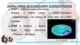
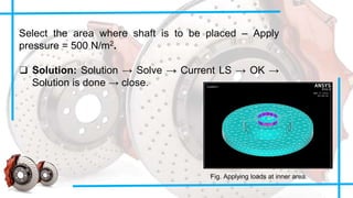
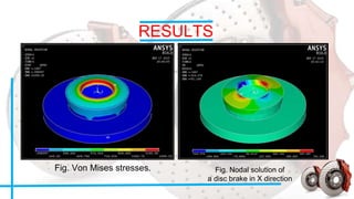
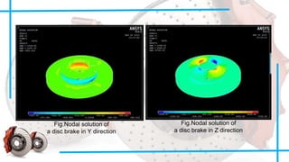
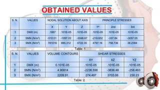
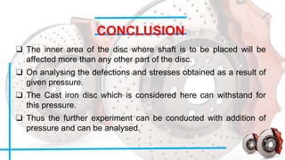
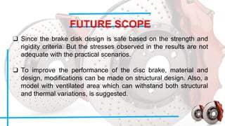


This document summarizes a structural analysis of a brake disc conducted by students. They modeled a disc brake in ANSYS, applied appropriate loads and boundary conditions, and analyzed the results. Von Mises stresses were highest at the inner area where the shaft connects. Deflections and stresses obtained indicate the cast iron disc can withstand the applied pressure. The analysis can be improved by modifying the material or design, or adding ventilated areas to withstand thermal variations.


