Downloaded 147 times

![Computer Aided Engineering MET-300 Project – Technical Report
Farmingdale State College 04/29/2015
10
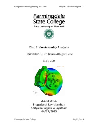
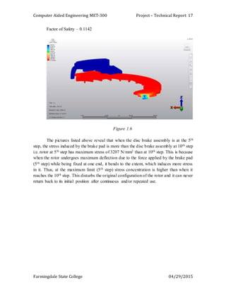
Capture rate – It analyzes the component in several steps and
increments. More is the value of the capture rate, better is the
simulation result.
Under the parameters section, the capture rate was selected and
defined as 5 for 1-second forward cycle.
So, for a total of 2 seconds, the total time of 10 seconds was made
as a capture rate.
SelectionofMaterials
• The brake disc or rotor is usually made up of cast iron, but in some cases it is
made up of composites such as reinforced carbon–carbon or ceramic matrix
composites.
• We have used two different sets of material type. They are: -
a. Caliper: Aluminum 6061 - O
Brake Pad: ASTM Steel A36
Rotor: Cast Iron ASTM A48 Grade 50
b. Caliper: Aluminum 6061 - O
Brake Pad: Steel AISI 4130
Rotor: Titanium Carbide (TiC)
Mechanical Properties
Aluminum 6061– O [CaliperMaterial]
Metric English
Hardness, Brinell 30 30
Ultimate Tensile Strength 124 MPa 18000 psi
Tensile Yield Strength 55.2 MPa 8000 psi
Elongation at Break 25 % 25 %
Elongation at Break 30 % 30 %
Modulus of Elasticity 68.9 GPa 10000 ksi
Ultimate Bearing Strength 228 MPa 33100 psi
Bearing Yield Strength 103 MPa 14900 psi](https://image.slidesharecdn.com/technicalreportcae-170112214950/85/Finite-Element-Analysis-of-Disk-brake-assembly-10-320.jpg)
![Computer Aided Engineering MET-300 Project – Technical Report
Farmingdale State College 04/29/2015
11
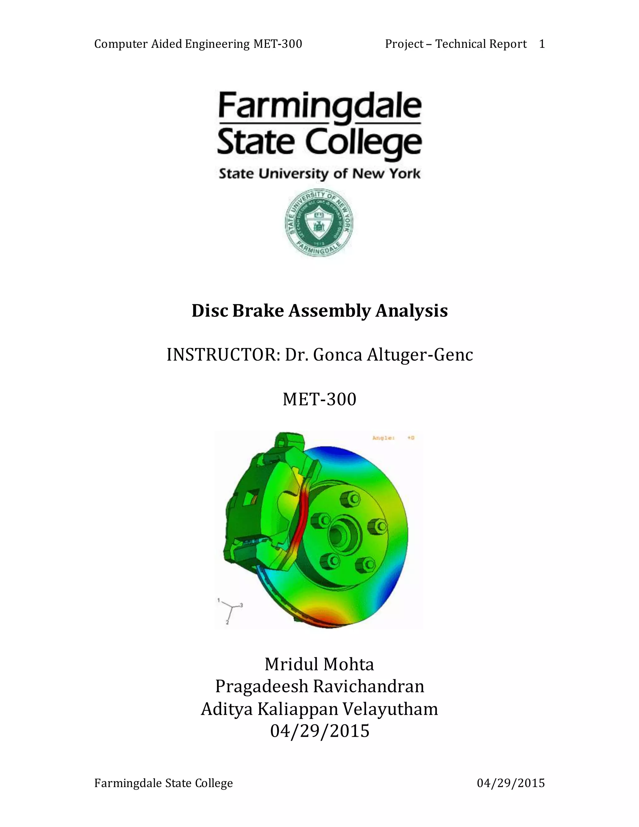
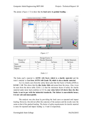
Poisson's Ratio 0.33 0.33
Fatigue Strength 62.1 MPa 9000 psi
Machinability 30 % 30 %
Shear Modulus 26 GPa 3770 ksi
Shear Strength 82.7 MPa 12000 psi
ASTM A36 Steel [Brake Pad Set - 1]
Tensile Strength, Ultimate 400 - 550 MPa 58000 - 79800 psi
Tensile Strength, Yield 250 MPa 36300 psi
Elongation at Break 20 % 20 %
Modulus of Elasticity 200 GPa 29000 ksi
Bulk Modulus 160 GPa 23200 ksi
Poisson’s Ratio 0.26 0.26
Shear Modulus 79.3 GPa 11500 ksi
AISI 4130 Steel, normalized at1600°F[BrakePad - Set 2]
Hardness, Brinell 197 197
Hardness, Knoop 219 219
Hardness, Rockwell B 92 92
Hardness, Rockwell C 13 13
Hardness, Vickers 207 207
Tensile Strength, Ultimate 670 MPa 97200 psi
Tensile Strength, Yield 435 MPa 63100 psi](https://image.slidesharecdn.com/technicalreportcae-170112214950/85/Finite-Element-Analysis-of-Disk-brake-assembly-11-320.jpg)
![Computer Aided Engineering MET-300 Project – Technical Report
Farmingdale State College 04/29/2015
12
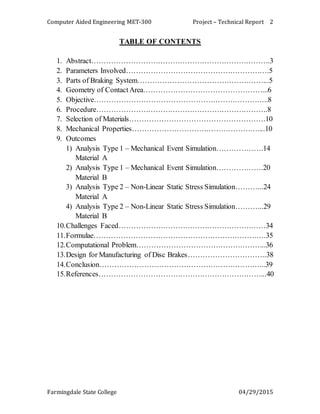
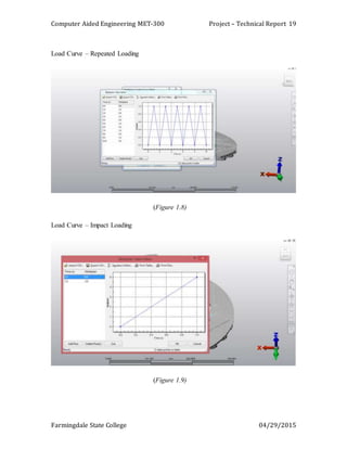
Elongation at Break 25.5 % 25.5 %
Reduction of Area 60 % 60 %
Modulus of Elasticity 205 GPa 29700 ksi
Bulk Modulus 140 GPa 20300 ksi
Poisson's Ratio 0.29 0.29
Izod Impact 87 J 64.2 ft-lb
Machinability 70 % 70 %
Shear Modulus 80 GPa 11600 ksi
Gray Cast Iron Grade50 [Rotor Set - 1]
Compressive (Crushing) Strength 1130 MPa (164 x 103 psi)
Density 7.2 g/cm3 (450 lb./ft3)
Elastic (Young's, Tensile) Modulus 130 to 160 GPa (19 to 23 x 106 psi)
Elongation at Break 1 %
Fatigue Strength (Endurance Limit) 148 MPa (21 x 103 psi)
Fracture Toughness 650 MPa-m1/2
Melting Onset (Solidus) 1090 °C (1990 °F)
Shear Strength 503 MPa (73 x 103 psi)
Specific Heat Capacity 450 J/kg-K
Strength to Weight Ratio 48 to 57 kN-m/kg
Tensile Strength: Ultimate (UTS) 345 to 410 MPa (50 to 59 x 103 psi)
Tensile Strength: Yield (Proof) 228 MPa (33 x 103 psi)
Thermal Conductivity 46 W/m-K
Thermal Diffusivity 14](https://image.slidesharecdn.com/technicalreportcae-170112214950/85/Finite-Element-Analysis-of-Disk-brake-assembly-12-320.jpg)
![Computer Aided Engineering MET-300 Project – Technical Report
Farmingdale State College 04/29/2015
13
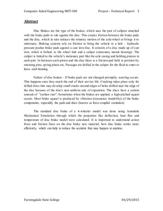
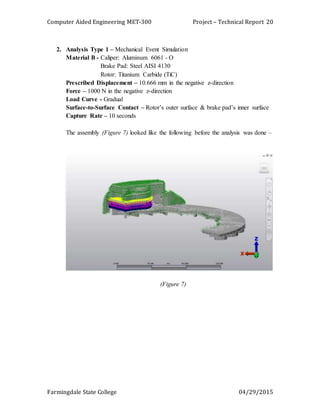
Thermal Expansion 10.5 µm/m-K
Titanium Carbide[Rotor Set - 2]
Knoop Micro hardness 2400 2000 – 2400
Hardness, Rockwell A 93 93
Vickers Micro hardness 3200 3200
Tensile Strength, Ultimate 258 MPa 37400 psi
Modulus of Elasticity 448 - 451 GPa 65000 - 65400 ksi
Poisson’s Ratio 0.18 - 0.19 0.18 - 0.19
Shear Modulus 110 - 193 GPa 16000 - 28000 ksi
Shear Strength 89.0MPa
@Temperature 1925 °C
12900psi
@Temperature 3497 °F
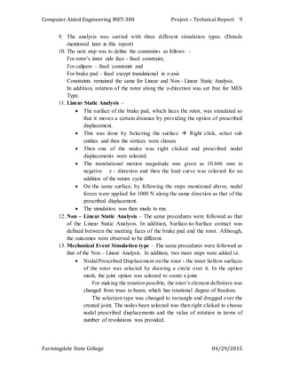
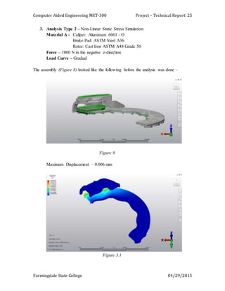
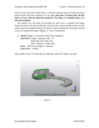
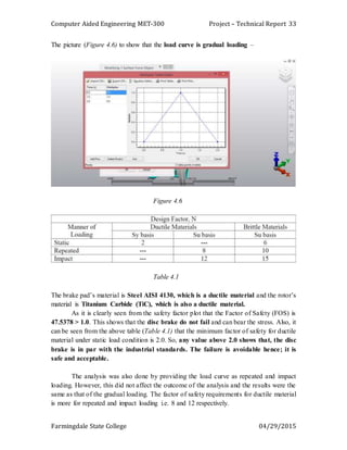
The assembly (Figure 6) looked like the following upon meshing–
Figure 6](https://image.slidesharecdn.com/technicalreportcae-170112214950/85/Finite-Element-Analysis-of-Disk-brake-assembly-13-320.jpg)
![Computer Aided Engineering MET-300 Project – Technical Report
Farmingdale State College 04/29/2015
36
Maximum temperature subjected to = 350°C
Maximum pressure subjected to = 1MPa (E6 Pa)
Forces Acting On Rotor Due To Contact with Brake Pads
Tangential force between pad and rotor (Inner face)
FTRI = µ1.FRI
Where, FTRI = Normal force between pad brake and Rotor (Inner)
µ1 = Coefficient of friction = 0.5
FRI = Pmax / 2 × A pad brake area
So, FTRI = µ1.FRI
FTRI = (0.5)(0.5)(E6 N/sq.m) (2000E6 sq.m)
FTRI = 500 N
Tangential force between pad and rotor (outer face), FTRO.
In this FTRO equal FTRI because same normal force and same material
Brake Torque (TB):
With the assumption of equal coefficients of friction and normal forces FR on the inner
and outer faces:
TB = FT.R
Where TB = Brake torque
µ = Coefficient of friction
FT = Total normal forces on disc brake, [FTRI + FTRO]
FT = 1000 N
R = Radius of rotor disc
So, TB = (1000) (120E-3)
TB = 120 N.m
Brake Distance (x) –
We know that tangential braking force acting at the point of contact of the brake, and
Work done = FT. x (Equation A)
Where FT = FTRI + FTRO
X = Distance travelled (in meter) by the vehicle before it come to rest.
We know kinetic energy of the vehicle.
Kinetic energy = (m.v^2) / 2 (Equation B)
Where m = Mass of vehicle
v = Velocity of vehicle
In order to bring the vehicle to rest, the work done against friction must be equal to
kinetic energy of the vehicle.](https://image.slidesharecdn.com/technicalreportcae-170112214950/85/Finite-Element-Analysis-of-Disk-brake-assembly-36-320.jpg)
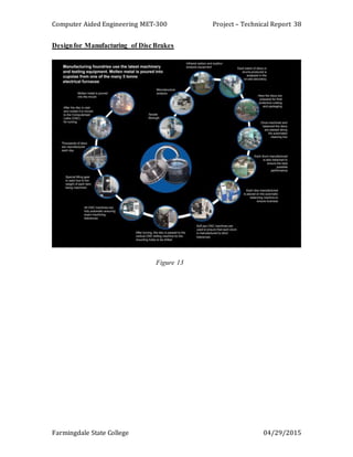

This technical report details an analysis of a disc brake assembly using Autodesk mechanical simulation, focusing on different materials to assess their performance under various loading conditions. It outlines the components of the braking system, the simulation procedures, and the outcomes, which highlight the failure of certain materials to meet safety factor requirements. The findings indicate that using ductile materials like cast iron and steel in the assembly resulted in factors of safety below acceptable industry standards, suggesting the design is unsafe for practical application.


