Downloaded 125 times


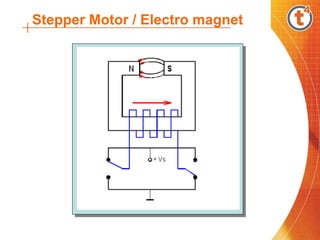
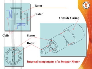
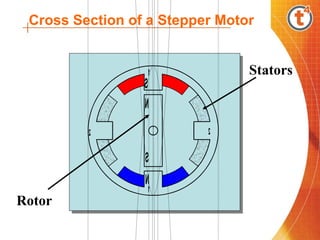
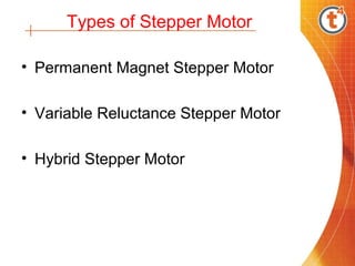
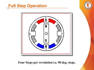
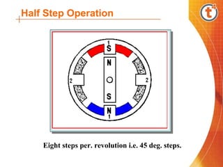
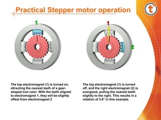
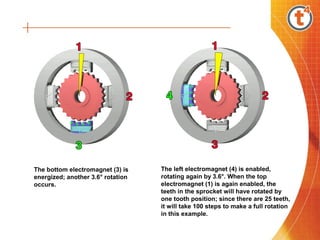
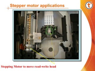
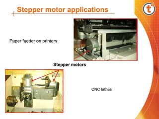
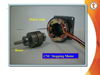
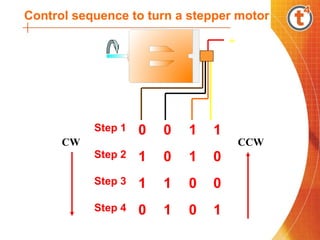

Stepper motors are capable of precise motion in increments and convert electronic pulses into proportional mechanical movement. They have a rotor inside a stator with electromagnets that pull the rotor teeth into alignment as different coils are energized, resulting in rotation. There are several types including permanent magnet, variable reluctance, and hybrid. Stepper motors can operate in full or half step modes, rotating the shaft by 90 or 45 degrees respectively with each pulse. They are used in applications like printers, CNC machines, and disk drives where precise positioning is needed.