Downloaded 4,212 times


![Generation of Electricity through Speed Breaker Mechanism
18
c. Pitch Diameter (P.D.):
The diameter across to the pitch circle which is Followed by the centers of the chain pins as sprocket revolves in mesh with the chain. PD= PITCHSIN (180/Nt)
d. Outside Diameter (O.D.):
The measurement from the tip of sprocket tooth across to the corresponding point directly across the sprocket. It is comparatively unimportant as the tooth length is not vital to proper meshing with the chain. The outside diameter may vary depending on type of cutter used.
OD = (Pitch) (.6 + COT [180 / Nt])
e. Hub Diameter (HOD):
That distance across the hub from one side to another. This diameter must not exceed the calculated diameter of the inside chain side bars.
f. Maximum Sprocket:
Maximum Sprocket Bore is determined by the required Bore hub wall thickness for proper strength. Allowance must be made for keyway and setscrews.
g. Face Width:
Face width is limited in its maximum dimension to allow proper clearance to provide for chain engagement and disengagement. The minimum width is limited to provide the proper strength to carry the imposed loads.
h. Length thru Bore:
Length Thru Bore (or L.T.B.) must be sufficient to allow LTB) a long enough key withstand the torque transmitted by the shaft. This also assures stability of the sprocket on the shaft.](https://image.slidesharecdn.com/projectreporttitle-140911184735-phpapp01/85/GENERATION-OF-ELECTRICITY-THROUGH-SPEED-BREAKER-25-320.jpg)


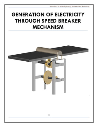
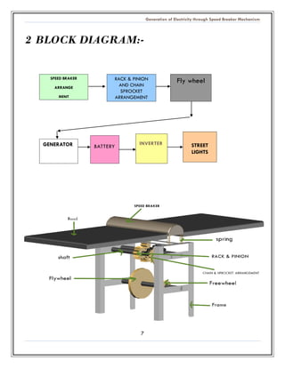
This document describes a project to generate electricity from speed breakers on roads. As vehicles pass over speed breakers, kinetic energy is wasted through heat and friction. This project aims to convert that wasted energy into electrical energy. It proposes installing movable speed breakers connected to a rack and pinion mechanism to convert vertical motion into rotational motion. This rotation would generate electricity using standard generators. The document outlines the working principle, components, advantages, and scope of the project. It aims to provide a sustainable energy source by tapping into kinetic energy from traffic on busy roads.